- Preface
- Cisco ONS Documentation Roadmap for Release 9.8.x
- New and Changed Information
- Chapter 1, Install the Cisco ONS 15454, ONS 15454 M2, and ONS 15454 M6 Shelf
- Chapter 2, Connecting the PC and Logging into the GUI
- Chapter 3, Install the Control Cards
- Chapter 4, Setup Optical Service Channel Cards
- Chapter 5, Optical Amplifier Cards
- Chapter 6, Provision Multiplexer and Demultiplexer Cards
- Chapter 7, Setup Tunable Dispersion Compensating Units
- Chapter 8, Provision Protection Switching Module
- Chapter 9, Optical Add/Drop Cards
- Chapter 10, Reconfigurable Optical Add/Drop Cards
- Chapter 11, Provision Transponder and Muxponder Cards
- Chapter 12, Node Reference
- Chapter 13, Network Reference
- Chapter 14, Turn Up a Node
- Chapter 15, Perform Node Acceptance Tests
- Chapter 16, Turn Up a Network
- Chapter 17, Create Optical Channel Circuits and Provisionable Patchcords
- Chapter 18, Monitor Performance
- Chapter 19, Manage the Node
- Chapter 20, Alarm and TCA Monitoring and Management
- Chapter 21, Change DWDM Card Settings
- Chapter 22, Manage Network Connectivity
- Chapter 23, Upgrade, Add, and Remove Cards and Nodes
- Chapter 24, Maintain the Node
- Chapter 25, Security Reference
- Chapter 26, Timing Reference
- Chapter 27, SNMP
- Appendix A, CTC Operation, Information, and Shortcuts
- Appendix B, Hardware Specifications
- Appendix C, Administrative and Service States
- Appendix D, Configure GE_XP, 10GE_XP, GE_XPE, and 10GE_XPE Cards Using PCLI
- Appendix E, Pseudo Command Line Interface Reference
- Appendix F, Fiber and Connector Losses in Raman Link Configuration
- Appendix G, Card Features
- Appendix H, Network Element Defaults
Cisco ONS 15454 DWDM Configuration Guide, Release 9.8.x
Bias-Free Language
The documentation set for this product strives to use bias-free language. For the purposes of this documentation set, bias-free is defined as language that does not imply discrimination based on age, disability, gender, racial identity, ethnic identity, sexual orientation, socioeconomic status, and intersectionality. Exceptions may be present in the documentation due to language that is hardcoded in the user interfaces of the product software, language used based on RFP documentation, or language that is used by a referenced third-party product. Learn more about how Cisco is using Inclusive Language.
- Updated:
- July 9, 2014
Chapter: Chapter 7, Setup Tunable Dispersion Compensating Units
Setup Tunable Dispersion Compensating Units
This chapter explains the Tunable Dispersion Compensating Units (T-DCU) used in Cisco ONS 15454 dense wavelength division multiplexing (DWDM) networks. For card safety and compliance information, refer to the Regulatory Compliance and Safety Information for Cisco ONS Products document.

Note![]() Unless otherwise specified, “ONS 15454” refers to both ANSI and ETSI shelf assemblies.
Unless otherwise specified, “ONS 15454” refers to both ANSI and ETSI shelf assemblies.
The T-DCU unit compensates for chromatic dispersion (CD) of the transmission fiber. The T-DCU provides two line cards with varied set of tunable wavelengths to compensate for CD.
7.1 Card Overview
The T-DCU card provides a selectable set of discrete negative chromatic dispersion values to compensate for chromatic dispersion of the transmission line. The card operates over the entire C-band (in the range of 1529.0 nm to 1562.5 nm) and monitors the optical power at the input and the output ports. The two types of T-DCU line cards are:
Note![]() Each T-DCU card is marked with a symbol that corresponds to a slot (or slots) on the ONS 15454 shelf assembly. Cards should be installed in slots that have the same symbols. See the “Card Slot Requirements” section in the Cisco ONS 15454 Hardware Installation Guide.
Each T-DCU card is marked with a symbol that corresponds to a slot (or slots) on the ONS 15454 shelf assembly. Cards should be installed in slots that have the same symbols. See the “Card Slot Requirements” section in the Cisco ONS 15454 Hardware Installation Guide.
7.1.1 Card Summary
Table 7-1 lists and summarizes the information about the TDC-CC and TDC-FC cards.
|
|
|
|
|---|---|---|
The TDC-CC has one set of optical ports located on the faceplate. It operates in slots 1 to 6 and slots 12 to 17. |
See the TDC-CC and TDC-FC Cards section. |
|
The TDC-FC has one set of optical ports located on the faceplate. It operates in slots 1 to 6 and slots 12 to 17. |
7.2 Safety Labels
For information about safety labels, see the “Class 1M Laser Product Cards” section.
7.3 TDC-CC and TDC-FC Cards
The TDC-CC card provides 16 values of CD ranging from 0 to -1650 ps/nm with a granularity of 110 ps/nm in the C-band spectrum.
The TDC-FC card provides 16 values of CD ranging from 0 to -675 ps/nm with a granularity of 45 ps/nm in the C-band spectrum.
You can configure the TDC-CC and TDC-FC cards for the CD value listed in Table 7-2 .
|
|
|
|
|---|---|---|
0 1 |
02 |
|
|
1.The default value of the TDC-CC CD value for Coarse Unit is 0. |
7.3.1 Key Features
The TDC-CC and TDC-FC cards provide the following features:
- Single slot card with three LEDs on the front panel.
- Two LC-PC-II optical connectors on the front panel.
- Operates in slots from slot 1 to 6 and 12 to 17.
- Operates over the C-band (wavelengths from 1529 nm to 1562.5 nm) of the optical spectrum.
- Allows upto 16 provisionable CD values for chromatic dispersion compensation.
- Connects to OPT-PRE, OPT-AMP-C, OPT-RAMP-C, and OPT-RAMP-CE amplifiers and 40-SMR-1 and 40-SMR-2 cards.
- Supports performance monitoring and alarm handling for selectable thresholds.
- Allows monitoring and provisioning using CTC, SNMP, or TL1.
7.3.2 TDC-CC and TDC-FC Faceplate Diagram
Figure 7-1 shows the TDC-CC and TDC-FC faceplate diagram. The TDC-CC and TDC-FC cards can be installed or pulled out of operation from any user interface slot, without impacting other service cards operating within that shelf.
Figure 7-1 TDC-CC and TDC-FC Faceplates
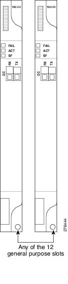
Note![]() The coarse T-DCU is identified with the card label as TDC-CC and the fine T-DCU with TDC-FC in the faceplate of the T-DCU card.
The coarse T-DCU is identified with the card label as TDC-CC and the fine T-DCU with TDC-FC in the faceplate of the T-DCU card.
7.3.3 Functioning of Optical Ports
The T-DCU unit contains the DC-RX (input) and DC-TX (output) ports. The optical signal enters the DC-RX port, compensates the chromatic dispersion and then exits from the DC-TX port.
7.3.4 TDC-CC and TDC-FC Block Diagram
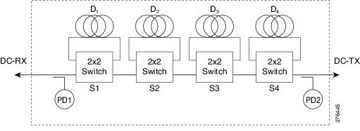
The TDC-CC and TDC-FC cards embed an optical module with four spools (D1, D2, D3, and D4) of dispersion compensating fiber that connects through the 2x2 bypass switches (Figure 7-2). Each bypass switch allows the corresponding dispersion compensation fiber spools to connect to the optical path from the DC-RX (input port) to the DC-TX (output port). The switch configuration selects the requested CD value and combines the four spools based on the 16 chromatic dispersion compensation values fetched. The photo diodes PD1 and PD2 are used to monitor the input and output ports respectively.
Figure 7-2 Block Diagram of TDC-CC and TDC-FC
7.3.5 TDC-CC and TDC-FC Cards Functions
7.4 Monitoring Optical Performance
The TDC-CC and TDC-FC cards monitor the optical input power and optical output power of the fiber. It monitors the insertion loss from the input (DC-RX) to the output (DC-TX) port, with the help of the two photodiodes PD1 and PD2. The TDC-CC and TDC-FC cards report the minimum, average, and maximum power statistics of each of the monitored ports or channels in the specific card. To view the optical power statistics of the TDC-CC and TDC-FC cards, refer to the Monitor Performance document. The performance data is recorded at 15 minutes and 24 hours intervals.
Note![]() You can view the performance monitoring (PM) data of the card using CTC, SNMP, and TL1 interfaces.
You can view the performance monitoring (PM) data of the card using CTC, SNMP, and TL1 interfaces.
Note![]() The PM data is stored on a wrap-around basis at 32 x 15 min. and 2 x 24 hour intervals.
The PM data is stored on a wrap-around basis at 32 x 15 min. and 2 x 24 hour intervals.
7.4.1 Related Procedures for TDC-CC and TDC-FC Cards
The following section lists procedures and tasks related to the configuration of the TDC-CC and TDC-FC cards:
 Feedback