- Preface
- Cisco ONS Documentation Roadmap for Release 9.2.1
- Chapter 1, CE-Series Ethernet Cards
- Chapter 2, E-Series and G-Series Ethernet Cards
-
- Chapter 3, ML-Series Cards Overview
- Chapter 4, CTC Operations
- Chapter 5, Initial Configuration
- Chapter 6, Configuring Interfaces
- Chapter 7, Configuring CDP
- Chapter 8, Configuring POS
- Chapter 9, Configuring Bridges
- Chapter 10, Configuring IEEE 802.1Q Tunneling and Layer 2 Protocol Tunneling
- Chapter 11, Configuring STP and RSTP
- Chapter 12, Configuring Link Aggregation
- Chapter 13, Configuring Security for the ML-Series Card
- Chapter 14, Configuring RMON
- Chapter 15, Configuring SNMP
- Chapter 16, Configuring VLAN
- Chapter 17, Configuring Networking Protocols
- Chapter 18, Configuring IRB
- Chapter 19, Configuring IEEE 802.17b Resilient Packet Ring
- Chapter 20, Configuring VRF Lite
- Chapter 21, Configuring Quality of Service
- Chapter 22, Configuring Ethernet over MPLS
- Chapter 23, Configuring the Switching Database Manager
- Chapter 24, Configuring Access Control Lists
- Chapter 25, Configuring Cisco Proprietary Resilient Packet Ring
-
- Chapter 26, ML-MR-10 Card Overview
- Chapter 27, IP Host Functionality on the ML-MR-10 Card
- Chapter 29: Configuring Security for the ML-MR-10 Card
- Chapter 30: Configuring IEEE 802.17b Resilient Packet Ring on the ML-MR-10 Card
- Chapter 31, Configuring POS on the ML-MR-10 Card
- Chapter 32, Configuring Card Port Protection on the ML-MR-10 Card
- Chapter 32, Configuring Ethernet Virtual Circuits and QoS on the ML-MR-10 Card
- Chapter 34: Configuring Link Agrregation on ML-MR-10 card
- Chapter 35, Configuring Ethernet OAM (IEEE 802.3ah), CFM (IEEE 802.1ag), and E-LMI on the ML-MR-10 Card
- Appendix A: CPU and Memory Utilization on the ML-MR-10 Card
- Appendix A, POS on ONS Ethernet Cards
- Appendix B, Command Reference
- Appendix C, Unsupported CLI Commands
- Appendix D, Using Technical Support
Cisco ONS 15454 and Cisco ONS 15454 SDH Ethernet Card Software Feature and Configuration Guide, Releases 9.0, 9.1, 9.2, and 9.2.1
Bias-Free Language
The documentation set for this product strives to use bias-free language. For the purposes of this documentation set, bias-free is defined as language that does not imply discrimination based on age, disability, gender, racial identity, ethnic identity, sexual orientation, socioeconomic status, and intersectionality. Exceptions may be present in the documentation due to language that is hardcoded in the user interfaces of the product software, language used based on RFP documentation, or language that is used by a referenced third-party product. Learn more about how Cisco is using Inclusive Language.
- Updated:
- March 3, 2010
Chapter: Chapter 34: Configuring Link Agrregation on ML-MR-10 card
Configuring Link Aggregation on the ML-MR-10 card
This chapter applies to the ML-MR-10 card and describes how to configure link aggregation for the ML-Series cards, both EtherChannel and packet-over-SONET/SDH (POS) channel. For additional information about the Cisco IOS commands used in this chapter, refer to the Cisco IOS Command Reference publication.
This chapter contains the following major sections:
•![]() Understanding Link Aggregation
Understanding Link Aggregation
•![]() Understanding Encapsulation over EtherChannel or POS Channel
Understanding Encapsulation over EtherChannel or POS Channel
•![]() Monitoring and Verifying EtherChannel and POS
Monitoring and Verifying EtherChannel and POS
•![]() Understanding Link Aggregation Control Protocol
Understanding Link Aggregation Control Protocol
Understanding Link Aggregation
The ML-MR-10 card offers both EtherChannel and POS channel. Traditionally EtherChannel is a trunking technology that groups together multiple full-duplex IEEE 802.3 Ethernet interfaces to provide fault-tolerant high-speed links between switches, routers, and servers. EtherChannel forms a single higher bandwidth routing or bridging endpoint and was designed primarily for host-to-switch connectivity. The ML-MR-10 card extends this link aggregation technology to bridged POS interfaces. POS channel is only supported with LEX encapsulation.
Link aggregation provides the following benefits:
•![]() Logical aggregation of bandwidth
Logical aggregation of bandwidth
•![]() Load balancing
Load balancing
•![]() Fault tolerance
Fault tolerance
Port channel is a term for both POS channel and EtherChannel. The port channel interface is treated as a single logical interface although it consists of multiple interfaces. Each port channel interfaces consists of one type of interface, either Fast Ethernet, Gigabit Ethernet, or POS. You must perform all port channel configurations on the port channel (EtherChannel or POS channel) interface rather than on the individual member Ethernet or POS interfaces. You can create the port channel interface by entering the interface port-channel interface configuration command.

Note ![]() You must perform all Cisco IOS configurations—such as bridging, routing, or parameter changes such as an MTU change—on the port channel (EtherChannel or POS channel) interface rather than on individual member Ethernet or POS interfaces.
You must perform all Cisco IOS configurations—such as bridging, routing, or parameter changes such as an MTU change—on the port channel (EtherChannel or POS channel) interface rather than on individual member Ethernet or POS interfaces.
Port channel connections are fully compatible with IEEE 802.1Q trunking and routing technologies. IEEE 802.1Q trunking can carry multiple VLANs across a port channel.
Each ML-MR-10 card supports up to ten port channel interfaces. A maximum of ten Gigabit Ethernet ports can be added into one Port-Channel.
Note ![]() If the number of POS ports configured on the ML-MR-10 are 26, the MLMR-10 card supports two port channel interfaces. However, a maximum of ten Gigabit Ethernet ports can be added into one port channel.
If the number of POS ports configured on the ML-MR-10 are 26, the MLMR-10 card supports two port channel interfaces. However, a maximum of ten Gigabit Ethernet ports can be added into one port channel.

Note ![]() Link aggregation across multiple ML-Series cards is not supported.
Link aggregation across multiple ML-Series cards is not supported.
Note ![]() Policing is not supported on port channel interfaces.
Policing is not supported on port channel interfaces.
Note ![]() The ML-Series does not support the routing of Subnetwork Access Protocol (SNAP) or Inter-Switch Link (ISL) encapsulated frames.
The ML-Series does not support the routing of Subnetwork Access Protocol (SNAP) or Inter-Switch Link (ISL) encapsulated frames.
Configuring EtherChannel
You can configure an FEC or a GEC by creating an EtherChannel interface (port channel) and assigning a network IP address. All interfaces that are members of a FEC or a GEC should have the same link parameters, such as duplex and speed.
To create an EtherChannel interface, perform the following procedure, beginning in global configuration mode:
For information on other configuration tasks for the EtherChannel, refer to the
Cisco IOS Configuration Fundamentals Configuration Guide.
To assign Ethernet interfaces to the EtherChannel, perform the following procedure, beginning in global configuration mode:
EtherChannel Configuration Example
Figure 34-1 shows an example of EtherChannel. The associated commands are provided in Example 34-1 (Switch A) and Example 34-2 (Switch B).
Figure 34-1 EtherChannel Example
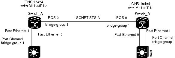
Example 34-1 Switch A Configuration
hostname Switch A
!
bridge 1 protocol ieee
!
interface Port-channel 1
no ip address
bridge-group 1
hold-queue 150 in
!
interface FastEthernet 0
no ip address
channel-group 1
!
interface FastEthernet 1
no ip address
channel-group 1
!
interface POS 0
no ip routing
no ip address
crc 32
bridge-group 1
pos flag c2 1
Example 34-2 Switch B Configuration
hostname Switch B
!
bridge 1 protocol ieee
!
interface Port-channel 1
no ip routing
no ip address
bridge-group 1
hold-queue 150 in
!
interface FastEthernet 0
no ip address
channel-group 1
!
interface FastEthernet 1
no ip address
channel-group 1
!
interface POS 0
no ip address
crc 32
bridge-group 1
pos flag c2 1
!
Understanding Encapsulation over EtherChannel or POS Channel
When configuring encapsulation over FEC, GEC, or POS, be sure to configure IEEE 802.1Q on the port-channel interface, not its member ports. However, certain attributes of port channel, such as duplex mode, need to be configured at the member port levels. Also make sure that you do not apply protocol-level configuration (such as an IP address or a bridge group assignment) to the member interfaces. All protocol-level configuration should be on the port channel or on its subinterface. You must configure IEEE 802.1Q encapsulation on the partner system of the EtherChannel as well.
Configuring Encapsulation over EtherChannel or POS Channel
To configure encapsulation over the EtherChannel or POS channel, perform the following procedure, beginning in global configuration mode:
Encapsulation over EtherChannel Example
Figure 34-2 shows an example of encapsulation over EtherChannel. The associated code is provided in Example 34-3 (Switch A) and Example 34-4 (Switch B).
Figure 34-2 Encapsulation over EtherChannel Example
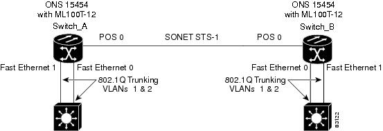
This encapsulation over EtherChannel example shows how to set up two ONS 15454s with ML100T-12 cards (Switch A and Switch B) to interoperate with two switches that also support IEEE 802.1Q encapsulation over EtherChannel. To set up this example, use the configurations in the following sections for both Switch A and Switch B.
Example 34-3 Switch A Configuration
hostname Switch A
!
bridge irb
bridge 1 protocol ieee
bridge 2 protocol ieee
!
interface Port-channel1
no ip address
hold-queue 150 in
!
interface Port-channel1.1
encapsulation dot1Q 1 native
bridge-group 1
!
interface Port-channel1.2
encapsulation dot1Q 2
bridge-group 2
!
interface FastEthernet0
no ip address
channel-group 1
!
interface FastEthernet1
no ip address
channel-group 1
!
interface POS0
no ip address
crc 32
pos flag c2 1
!
interface POS0.1
encapsulation dot1Q 1 native
bridge-group 1
!
interface POS0.2
encapsulation dot1Q 2
bridge-group 2
Example 34-4 Switch B Configuration
hostname Switch B
!
bridge irb
bridge 1 protocol ieee
bridge 2 protocol ieee
!
interface Port-channel1
no ip address
hold-queue 150 in
!
interface Port-channel1.1
encapsulation dot1Q 1 native
bridge-group 1
!
interface Port-channel1.2
encapsulation dot1Q 2
bridge-group 2
!
interface FastEthernet0
no ip address
channel-group 1
!
interface FastEthernet1
no ip address
channel-group 1
!
interface POS0
no ip address
crc 32
pos flag c2 1
!
interface POS0.1
encapsulation dot1Q 1 native
bridge-group 1
!
interface POS0.2
encapsulation dot1Q 2
bridge-group 2
!
Monitoring and Verifying EtherChannel and POS
After FEC, GEC, or POS is configured, you can monitor its status using the show interfaces port-channel command.
Example 34-5 show interfaces port-channel Command
Router# show int port-channel 1
Port-channel1 is up, line protocol is up
Hardware is FEChannel, address is 0005.9a39.6634 (bia 0000.0000.0000)
MTU 1500 bytes, BW 200000 Kbit, DLY 100 usec,
reliability 255/255, txload 1/255, rxload 1/255
Encapsulation ARPA, loopback not set
Keepalive set (10 sec)
Unknown duplex, Unknown Speed
ARP type: ARPA, ARP Timeout 04:00:00
No. of active members in this channel: 2
Member 0 : FastEthernet0 , Full-duplex, Auto Speed
Member 1 : FastEthernet1 , Full-duplex, Auto Speed
Last input 00:00:01, output 00:00:23, output hang never
Last clearing of "show interface" counters never
Input queue: 0/150/0/0 (size/max/drops/flushes); Total output drops: 0
Queueing strategy: fifo
Output queue :0/80 (size/max)
5 minute input rate 0 bits/sec, 0 packets/sec
5 minute output rate 0 bits/sec, 0 packets/sec
820 packets input, 59968 bytes
Received 0 broadcasts, 0 runts, 0 giants, 0 throttles
0 input errors, 0 CRC, 0 frame, 0 overrun, 0 ignored
0 watchdog, 0 multicast
0 input packets with dribble condition detected
32 packets output, 11264 bytes, 0 underruns
0 output errors, 0 collisions, 0 interface resets
0 babbles, 0 late collision, 0 deferred
0 lost carrier, 0 no carrier
0 output buffer failures, 0 output buffers swapped out.
Understanding Link Aggregation Control Protocol
In Software Release 8.5.0 and later, ML-MR-10 and CE-100T-8 cards can utilize the link aggregation control protocol (LACP) to govern reciprocal peer packet transmission with respect to LACP's detection of flawed packets. The cards' ports transport a signal transparently (that is, without intervention or termination). However, this transparent packet handling is done only if the LACP is not configured for the ML- MR-10 card.
Passive Mode and Active Mode
Passive or active modes are configured for a port and they differ in how they direct a card to transmit packets: In passive mode, the LACP resident on the node transmits packets only after it receives reciprocal valid packets from the peer node. In active mode, a node transmits packets irrespective of the LACP capability of its peer.
LACP Functions
LACP performs the following functions in the system:
•![]() Maintains configuration information in order to control aggregation
Maintains configuration information in order to control aggregation
•![]() Exchanges configuration information with other peer devices
Exchanges configuration information with other peer devices
•![]() Attaches or detaches ports from the link aggregation group based on the exchanged configuration information
Attaches or detaches ports from the link aggregation group based on the exchanged configuration information
•![]() Enables data flow when both sides of the aggregation group are synchronized
Enables data flow when both sides of the aggregation group are synchronized
In addition, LACP provides the following benefits:
•![]() Logical aggregation of bandwidth
Logical aggregation of bandwidth
•![]() Load balancing
Load balancing
•![]() Fault tolerance
Fault tolerance
LACP Parameters
LACP utilizes the following parameters to control aggregation:
System Identifier—A unique identification assigned to each system. It is the concatenation of the system priority and a globally administered individual MAC address.
Port Identification—A unique identifier for each physical port in the system. It is the concatenation of the port priority and the port number.
Port Capability Identification—An integer, called a key, that identifies one port's capability to aggregate with another port. There are two types of key: administrative and operational. An administrative key is configured by the network administrator, and an operational key is assigned by LACP to a port based on its aggregation capability.
Aggregation Identifier—A unique integer that is assigned to each aggregator and is used for identification within the system.
LACP Usage Scenarios
In Software Release 8.5.0 and later, LACP functions on ML-MR-10 cards in termination mode and on the CE-Series cards in transparent mode.
Termination Mode
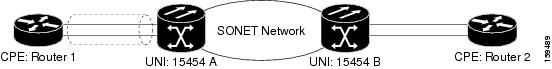
In termination mode, the link aggregation bundle terminates or originates at the ML-MR-10 card. To operate in this mode, LACP should be configured on the Ethernet interface. One protect SONET or SDH circuit can carry the aggregated Ethernet traffic of the bundle. The advantage of termination mode over transparent mode is that the network bandwidth is not wasted. However. the disadvantage is that there is no card protection between the CPE and UNI (ONS 15454) because all the links in the ML card bundle belong to the same card.
Figure 34-3 LACP Termination Mode Example
Transparent Mode
In Figure 34-4, the link aggregation bundle originates at router 1 and terminates at router 2. Transparent mode is enabled when the LACP packets are transmitted without any processing on a card. While functioning in this mode, the ML-100T-8 cards pass through LACP packets transparently so that the two CPE devices perform the link aggregation. To operate in this mode, no LACP configuration is required on the ML-100T-8 cards.
Figure 34-4 LACP Transparent Mode Example

Configuring LACP
To configure LACP over the EtherChannel, perform the following procedure, beginning in global configuration mode:
In Example 34-6, the topology includes two nodes with a GEC or FEC transport between them. This example shows one GEC interface on Node 1. (Up to four similar types of links per bundle are supported.)
Example 34-6 LACP Configuration Example
ML2-Node1# sh run int gi0
Building configuration...
Current configuration : 150 bytes
!
interface GigabitEthernet0
no ip address
no keepalive
duplex auto
speed auto
negotiation auto
channel-group 1 mode active
no cdp enable
end
ML2-Node1#
ML2-Node1# sh run int por1
Building configuration...
Current configuration : 144 bytes
!
interface Port-channel1
no ip address
no negotiation auto
service instance 30 ethernet1
encapsulation dot1q 30
bridge-domain 30
!
end
ML2-Node1#
ML2-Node1# sh lacp int
Flags: S - Device is requesting Slow LACPDUs
F - Device is requesting Fast LACPDUs
A - Device is in Active mode P - Device is in Passive mode
Channel group 1
LACP port Admin Oper Port Port
Port Flags State Priority Key Key Number State
Gi0 SA bndl 32768 0x1 0x1 0x5 0x3D
ML2-Node1#
Configuration remains same for the ML2-Node2 also.
Load Balancing on the ML-MR-10 card
The load balancing on the ML-MR-10 card can be configured through the following options:
•![]() source and destination MAC addresses
source and destination MAC addresses
•![]() VLAN ID contained in the SVLAN (outer) tag
VLAN ID contained in the SVLAN (outer) tag
Note ![]() The default load balancing mechanism on ML-MR-10 card is the source and destination MAC address.
The default load balancing mechanism on ML-MR-10 card is the source and destination MAC address.
MAC address based load balancing
The MAC address based load balancing is achieved by performing "XOR" (exclusive OR) operation on the last 4 least significant bits of the source MAC address and the destination MAC address.
Table 34-1 displays the ethernet traffic with 4 Gigabit Ethernet members on the port channel interfaces.
Table 34-2 displays the ethernet traffic with 3 Gigabit Ethernet members on the port channel interfaces.
Note ![]() The member of the port channel interface depends on the order in which the Gigabit Ethernet becomes an active member of the port channel interface. The order in which the members are added to the port channel can be found using the show interface port channel <port channel number> command in the EXEC mode.
The member of the port channel interface depends on the order in which the Gigabit Ethernet becomes an active member of the port channel interface. The order in which the members are added to the port channel can be found using the show interface port channel <port channel number> command in the EXEC mode.
VLAN Based Load Balancing
VLAN based load balancing is achieved by using the last 4 least significant bits of the incoming VLAN ID in the outer VLAN.
Table 34-3 displays the ethernet traffic with 3 Gigabit Ethernet members on the port channel interfaces.
Note ![]() The member of the port channel interface depends on the order in which the Gigabit Ethernet becomes an active member of the port channel interface. The order in which the members are added to the port channel can be found using the show interface port-channel <port-channel number> command in the EXEC mode.
The member of the port channel interface depends on the order in which the Gigabit Ethernet becomes an active member of the port channel interface. The order in which the members are added to the port channel can be found using the show interface port-channel <port-channel number> command in the EXEC mode.
With the 4 Gigabit Ethernet members, if the incoming VLAN ID is 20, the traffic will be sent on member-0. If the incoming VLAN ID is 30, the traffic will be sent on member-2.
Load Balancing Configuration Commands
Table 34-4 details the commands used to configure load balancing on the ML-Series cards and the ML-MR-10 card.
Example 34-7 show command configuration
Configuration:
!
interface Port-channel10
no ip address
no negotiation auto
load-balance vlan
service instance 20 ethernet
encapsulation dot1q 20
bridge-domain 20
!
service instance 30 ethernet
encapsulation dot1q 30
bridge-domain 30
!
!
!
interface GigabitEthernet1
no ip address
speed auto
duplex auto
negotiation auto
channel-group 10
no keepalive
!
interface GigabitEthernet2
no ip address
speed auto
duplex auto
negotiation auto
channel-group 10
no keepalive
!
interface GigabitEthernet9
no ip address
speed auto
duplex auto
negotiation auto
channel-group 10
no keepalive
Router#sh int port-channel 10
Port-channel10 is up, line protocol is up
Hardware is GEChannel, address is 001b.54c0.2643 (bia 0000.0000.0000)
MTU 9600 bytes, BW 2100000 Kbit, DLY 10 usec,
reliability 255/255, txload 1/255, rxload 1/255
Encapsulation ARPA, loopback not set
Keepalive set (10 sec)
ARP type: ARPA, ARP Timeout 04:00:00
No. of active members in this channel: 3
Member 0 : GigabitEthernet9 , Full-duplex, 100Mb/s
Member 1 : GigabitEthernet1 , Full-duplex, 1000Mb/s
Member 2 : GigabitEthernet2 , Full-duplex, 1000Mb/s
Last input never, output never, output hang never
Last clearing of "show interface" counters never
Input queue: 0/225/0/0 (size/max/drops/flushes); Total output drops: 0
Queueing strategy: fifo
Output queue: 0/120 (size/max)
5 minute input rate 0 bits/sec, 0 packets/sec
5 minute output rate 0 bits/sec, 0 packets/sec
0 packets input, 0 bytes, 0 no buffer
Received 0 broadcasts (0 IP multicasts)
0 runts, 0 giants, 0 throttles
0 input errors, 0 CRC, 0 frame, 0 overrun, 0 ignored
0 watchdog, 0 multicast, 0 pause input
48 packets output, 19080 bytes, 0 underruns
0 output errors, 0 collisions, 0 interface resets
0 babbles, 0 late collision, 0 deferred
0 lost carrier, 0 no carrier, 0 PAUSE output
0 output buffer failures, 0 output buffers swapped out
Router#
Router#show port-channel load-balance interface Port-channel 10 hash-table
Hash-value Interface
0 GigabitEthernet9
1 GigabitEthernet1
2 GigabitEthernet2
3 GigabitEthernet9
4 GigabitEthernet1
5 GigabitEthernet2
6 GigabitEthernet9
7 GigabitEthernet1
8 GigabitEthernet2
9 GigabitEthernet9
10 GigabitEthernet1
11 GigabitEthernet2
12 GigabitEthernet9
13 GigabitEthernet1
14 GigabitEthernet2
15 GigabitEthernet9
Router#
 Feedback