- Prime Network Customization Overview
- Modeling and Displaying Additional NE Properties
- Adding Support for New Devices, Software Versions and Modules Using the VCB
- Creating Commands and Command Scripts to Perform Device Configuration Operations
- Deploying Activation Workflows to Devices Using Transaction Manager
- Adding Support for New Events Using the VCB
- Adding New Threshold-Crossing Alarms
- Adding External Launch Points to the GUI Client
- Soft Properties: Supported Parsing Operators, Rules, and Regular Expressions
- VCB: CLI Commands and Template Reference
- Command Manager and Command Builder: Macro Language and Beanshell Reference
Cisco Prime Network Customization Guide, 5.0
Bias-Free Language
The documentation set for this product strives to use bias-free language. For the purposes of this documentation set, bias-free is defined as language that does not imply discrimination based on age, disability, gender, racial identity, ethnic identity, sexual orientation, socioeconomic status, and intersectionality. Exceptions may be present in the documentation due to language that is hardcoded in the user interfaces of the product software, language used based on RFP documentation, or language that is used by a referenced third-party product. Learn more about how Cisco is using Inclusive Language.
- Updated:
- March 2, 2016
Chapter: Adding Support for New Devices, Software Versions and Modules Using the VCB
- VCB Overview
- Comparison of GenericSNMP VNEs, U-VNEs, and Developed VNEs
- Identifying Supported Devices
- Adding Support for Additional Device Types by Creating U-VNEs
- Adding Support for Additional Software Versions
- Add Support for Additional Modules
- Testing and Certifying VCB Customizations
- Deploying VCB Customizations to Your Production Environment
- Deleting VNE Customizations from the Registry
Adding Support for New Devices, Software Versions and Modules Using the VCB
This chapter describes using the VNE Customization Builder (VCB) to add support for currently unsupported devices, software versions, and modules. For information about adding support for new events, see Adding Support for New Events Using the VCB.
This chapter contains the following topics:
- VCB Overview
- Comparison of Generic SNMP VNEs, U-VNEs, and Developed VNEs
- Adding Support for Additional Device Types by Creating U-VNEs
- Adding Support for Additional Software Versions
- Add Support for Additional Modules
- Testing and Certifying VCB Customizations
- Deploying VCB Customizations to Your Production Environment
- Deleting VNE Customizations from the Registry
VCB Overview
The VCB is a tool that allows advanced users to extend the “out-of-the-box” support and capabilities of Prime Network:
- Enable discovery of currently unsupported device types by creating user-defined VNE drivers, known as U-VNEs.
- Clone from an existing VNE driver to manage new devices that belong to an existing supported device family.
- Extend the discovery and management capabilities of existing VNE drivers to enable Prime Network to:
– Recognize cards that would otherwise be treated as “Unknown”.
– Process syslogs, traps, or service events as Prime Network events.
– Recognize additional software versions, such as maintenance releases of Cisco IOS and other software.

Note An event is generated for all VCB write operations (add, update, override, and delete) and is displayed in the System tab in the Prime Network Events GUI client.
VCB functions can be performed using the GUI interface that is available in the Prime Network Administration application (from the Tools menu), or by executing VCB commands in the Command Line Interface (CLI).
If you are new to the VCB, we recommend using the VCB GUI. If you are already familiar with using the CLI to perform VCB functions, or you want to perform more advanced VCB functions that are not yet included in the GUI, you can use the CLI.
Accessing the VCB
You can access the VCB through Prime Network Administration or by specifying a URL in your web browser. To open the VCB:
Step 1 In Prime Network Administration, choose Tools > VNE Customization Builder.
In your web browser, enter the following URL. The gateway-IP can be an IPv6 address.
https://gateway-IP:8043/prime-network-web
Step 2 Enter the login credentials and then select VNE Customization Builder in the Home page. The VCB opens, and the VNE Drivers page is displayed.
Note Only two users can be logged into the VCB GUI client at one time.
Figure 3-1 VCB - VNE Drivers Page
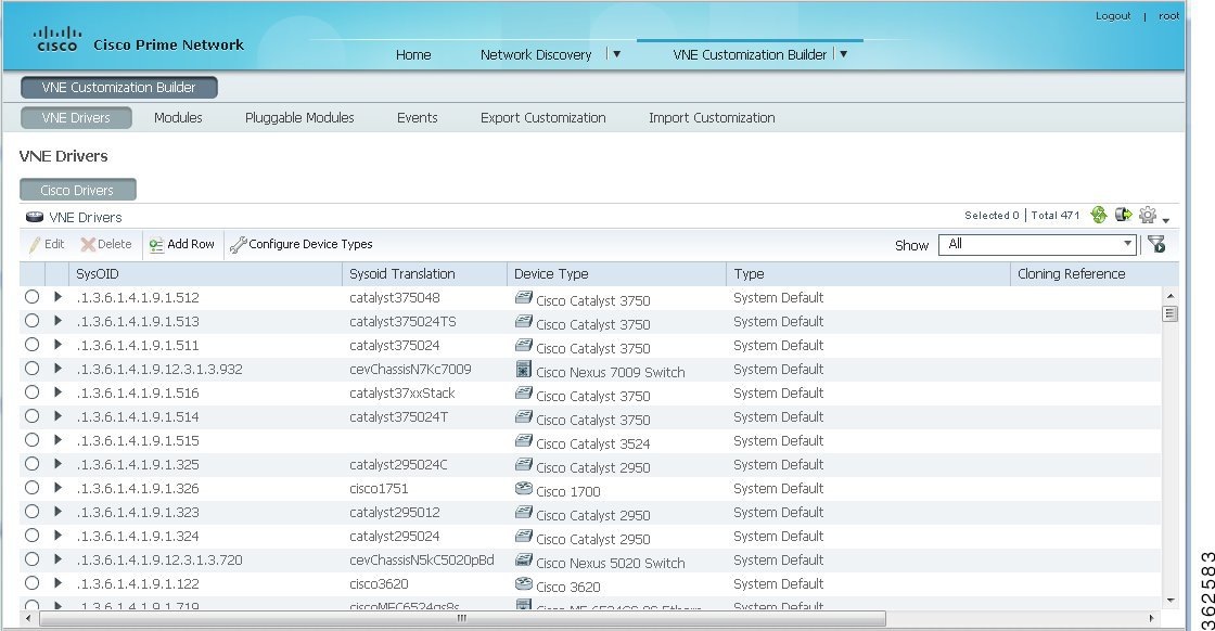
Note You can reorder the columns by dragging and dropping the column headers. You can also determine which columns will be displayed by using the Settings tool in the toolbar above the table.
The VCB displays the details of the Cisco and the third-party (non-Cisco) VNE drivers in separate tabs as Prime Network supports separate installation directories and registry service for Cisco and non-Cisco drivers. Non-Cisco VNEs do not support pluggable module specification, and the pluggable module information is retrieved from the network element itself.
Note The Non-Cisco Drivers tab in VCB GUI is displayed only after successful installation of a non-Cisco device package in Prime Network.
Comparison of Generic SNMP VNEs, U-VNEs, and Developed VNEs
Before using the VCB to add support for unsupported network elements, you should understand the difference between the types of VNEs.
A VNE for a supported NE that was developed by Cisco and supplied with the product or through a downloadable Device Package. These VNEs are created using the Prime Network Administration GUI client.
Note You should always use a developed VNE, if possible, and extend it using the VCB, if necessary. Developed VNE drivers are designed and tuned for specific technologies and devices, while U-VNEs model a subset of device capabilities.
Generic SNMP VNEs are usually created to monitor the most basic inventory information for an unsupported NE. These VNEs are created using the Prime Network Administration GUI client and by choosing Generic SNMP as the VNE Type. (Supported VNE types are AutoDetect, Cloud, ICMP, and Generic SNMP.)
Use the VCB to extend Generic SNMP VNEs to monitor unsupported events.
A U-VNE is a user-defined VNE created using the VCB to enable support for an unsupported device. A U-VNE can be created from scratch, based on a specific U-VNE template, or it can be created by cloning an existing supported device.
Features, advantages, and limitations of template-based U-VNEs are template-dependent. The GenericUVNE template supplies the same level of modelling as a Generic SNMP VNE. You can then further extend the U-VNE for additional event recognition using the VCB.
Table 3-1 shows the differences levels of support for Prime Network features in Generic SNMP VNEs, U-VNEs, and developed VNEs.
Note The information in this table is for comparative purposes only. The support provided by each U-VNE template might vary from template to template.
Standard traps that are supported by Generic SNMP VNEs. Can be extended to support proprietary traps and syslogs. |
Standard and proprietary traps and syslogs defined in the U-VNE template or NE instrumentation of cloned device. Syslogs are not supported by the GenericUVNE template but it can be extended to support proprietary traps and syslogs. |
||
Standard MIB-II and private MIBs for physical inventory discovery depending on template or cloned device. Can import traps to add event recognition. Based on most commonly used subset of standard MIB-II MIBs which some device manufacturers might alter; information from the proprietary implementation of third-party device vendors is not available through the use of standard MIBs. |
|||
Protocol used to query depends on setting in template or cloned device. |
|||
Yes (CDP is supported for Cisco devices). Template-based U-VNEs support the instrumentation defined in template |
|||
Routing table, ARP table, default bridge, IP interfaces1 |
Technologies and NE instrumentation supported in Prime Network |
||
Yes (for factory-defined events only, provided that the related technologies are supported by the U-VNE2 or cloned device). Events are associated to managed element. For events that were added via the VCB, correlation is done based on the DC key (correlation using network flow is not supported). Event is correlated to service events with the same source. Users cannot customize correlation parameters such as weight, correlation delay, and so on. Root-cause events cannot be added via the VCB. |
Yes (for factory-defined events). For events that were added via the VCB, correlation is done based on the DC key (correlation using network flow is not supported). Event is correlated to service events with the same source. Users cannot customize correlation parameters such as weight, correlation delay, and so on. Root-cause events cannot be added via the VCB. |
||
Only physical and Ethernet are supported. Template-based U-VNEs: Provide limited support for path tracing. If U-VNE does not support routing, network paths that traverse the U-VNE will stop and the result of the trace will show only the path to or from the U-VNE. Exact behavior depends on technologies used by NE, level of adherence to standard MIB support, and location of U-VNE on the path. |
|||
Template-based U-VNEs: Only physical and Ethernet are supported. Supported technologies are documented in the templates. Dynamic topology discovery is limited to U-VNEs on the network edge that are connected to a developed VNE. U-VNEs support IP topologies on high-level data link control (HDLC) and serial ports in point-to-point links, with no duplicate IP addresses, and same IP subnet. Cloned U-VNEs: Depends on the VNE from which it was cloned. 1 |
Identifying Supported Devices
The VNE Drivers tab provides a tabular view of all the supported device types and identifies whether they are system-defined (native Prime Network support) or user-defined (support added by Prime Network user using the VCB). It also provides the following information for each supported device:
- SysOID—The sysOID of the device.
- SysOID Translation—the MIB name of the device, derived from the sysOID. This a unique identifier for the device and provides more granular identification of the device than the device type. For example, the device type might be Cisco 3750 but the SysOID identifies the exact model of 3750 that is supported, for example, Catalyst375024TS.
- Device Type—The device family to which the supported device belongs.
- Type—System-defined or user-defined.
- Cloning Reference—If the U-VNE was created by cloning, this shows the cloning method used, either GenericUVNE or Entitymib.
- Overriding System Default—Shows as True if a system-defined device has been extended.
To get more details for each supported device, click the arrow on the extreme left to expand the display.
Adding Support for Additional Device Types by Creating U-VNEs
Using the VCB, you can enable Prime Network to discover and manage devices that have no system-defined VNE driver and are therefore not currently supported. To enable support for additional device types, you create a U-VNE and can then add the VNE to Prime Network in the normal manner, using the Administration GUI client. It will be modeled and added to the Prime Network device inventory. The level of modeling depends on the amount of detail provided to the system when you create the U-VNE.
Prime Network creates the registry information for these VNEs and saves it in site.xml, which is the registry location where all local changes should be stored. As with all VNEs, to maintain a live model of each network element and the entire network, VNEs must have connectivity with the device.
Note User-defined VNEs created with the VCB are not a replacement for developed VNE drivers. Developed VNE drivers are packaged with the Prime Network product and are also available in downloadable Device Packages. Developed VNE drivers are designed and tuned for specific technologies and devices, while U-VNEs model a subset of device capabilities.
These topics describe the methods for adding support for a new device type:
- Methods for Creating U-VNEs—Overview
- Creating a U-VNE Using the GenericUVNE Template
- Create a U-VNE by Cloning
Methods for Creating U-VNEs—Overview
Several approaches are available for creating U-VNEs. Depending on the approach you choose, the modeling capabilities will be more specific or less specific. Table 3-2 lists the supported methods and how to choose the one that is appropriate for your situation.
Creating a U-VNE Using the GenericUVNE Template
The following example shows how to enable support for an unsupported device by creating a U-VNE. For the purposes of this example, we will create a U-VNE to enable support for a Linux server. The U-VNE will be based on the GenericUVNE template. See U-VNE Templates for more information about this template.
- Make sure this is the proper method for your situation by checking the information in Methods for Creating U-VNEs—Overview.
- Obtain the sysOID of the NE you want to manage. The sysOID can be retrieved from the properties of the system event generated for an unsupported device (shown in Prime Network Vision or Prime Network Events). Alternatively, you can query the device using the snmp get command.
- Confirm that Prime Network does not support the sysOID. You can do this by filtering the VNE drivers list in the VCB GUI by the sysOID. If it is not found, it is not supported.
Step 1 Access the VCB, as described in Accessing the VCB.
Step 2 In the VNE Drivers tab, click Add Row .
Step 3 In the SysOID field, enter the sysOID of the new device. Note that after you have saved the U-VNE, the SysOID will be automatically translated to a unique device name plus identifier (if a compiled MIB version is available). This value will be displayed in the SysOID Translation column.
Step 4 Specify the name that will represent the device in the Prime Network GUI by creating a new device type, as follows:
a. In the Device Type field, click the down arrow to display the Device Type Selector.
b. Click the Tools icon in the upper right area of the Device Type Selector and select Add .
c. In the Device Type field, enter the device name that will represent the device in the Prime Network maps and element tables. We recommend that you prefix the device type name with the network element vendor name for easy identification.
d. In the Category field, select the category to which the device belongs. In this case, select Server .
e. In the Device Series field, specify the device series to which the device belongs.
f. Click OK . The new Device Type name will appear in the Device Type field.
Step 5 In the Type field, select User Defined VNE - by Template .
Step 6 In the Cloning Reference field, select GenericUVNE .
Step 8 Complete tests and certify the customization; see Testing and Certifying VCB Customizations.
Create a U-VNE by Cloning
This section describes how to enable support for an unsupported device by cloning a developed VNE driver from a supported device series or family. The cloned U-VNE inherits the behavior of the source VNE driver, and can be further extended using the VCB to add more device module discovery and event recognition.
- Make sure this is the proper method for your situation by checking the information in Methods for Creating U-VNEs—Overview.
- Obtain the sysOID of the NE you want to manage. The sysOID can be retrieved from the properties of the system event generated for an unsupported device (shown in Prime Network Vision or Prime Network Events). Alternatively, you can query the device using the snmp get command.
- Confirm that Prime Network does not support the sysOID. You can do this by filtering the VNE drivers list in the VCB GUI by the sysOID. If it is not found, it is not supported.
Step 1 Access the VCB, as described in Accessing the VCB.
Step 2 In the VNE Drivers tab, click Add Row .
Step 3 In the SysOID field, enter the sysOID of the new device.
Step 4 In the Device Type field, select the device type that will represent the new supported device in the Prime Network maps and element tables. If necessary, you can create a new device type from the Tools icon in the Device Type selector.
Step 5 To clone from a supported device family: In the Type field, select
User Defined VNE - by Device Family
.
To clone from a supported software version: In the Type field, select
User Defined VNE - by Software Version
, then select the device series and the scheme.
Note Cloning by software version performs two customizations in a single operation. It clones both the device type and software versions. The new driver will be listed in the GUI as cloned by device.
Step 6 In the Cloning Reference field, specify the item from which you want to clone the new VNE.
Step 8 Complete tests and certify the customization; see Testing and Certifying VCB Customizations.
Defining a Device Type to Determine the GUI Representation of VNE Drivers
Each VNE is represented by a specific name and icon in the maps and element tables. The device type determines the name used to represent the VNE while the device family determines the icon used to represent the VNE. When you create a U-VNE, you need to select a device type so that the system knows how to represent the new device in the GUI. If none of the existing device types is a suitable representation of your U-VNE, you can create a new device type. You can create a new device type in one of the following ways:
- From the VNE drivers window, during the VNE driver creation/editing process. See Creating a U-VNE Using the GenericUVNE Template.
- From the Device Types window, as described below.
Step 1 Access the VCB, as described in Accessing the VCB.
Step 2 In the VNE Drivers tab, click Configure Device Types . The Device Types window appears.
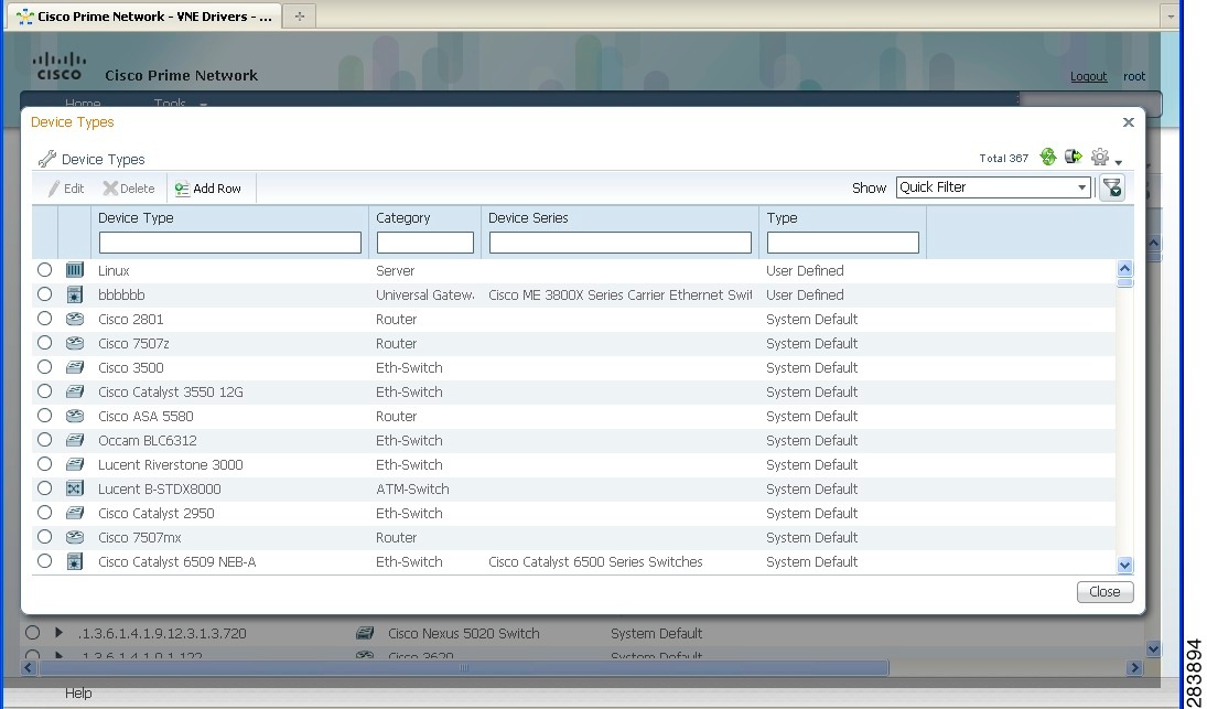
The Device Types window provides a table listing all the available device types.
Step 3 Click Add Row . A row is added to the device types table, enabling you to define the parameters of the new device type.
Step 4 Define the following parameters:
Adding Support for Additional Software Versions
Note You cannot edit or delete system default software versions.
The VCB enables you add support for additional software versions and to manage currently supported software versions.
Step 1 Access the VCB, as described in Accessing the VCB.
Step 2 In the VNE Drivers tab, expand the VNE driver for which you want to add a supported software version by clicking on the arrow on the left.
Step 3 Click Supported s/w versions in the Software Versions field.
The list of currently supported software for the selected VNE driver is displayed.
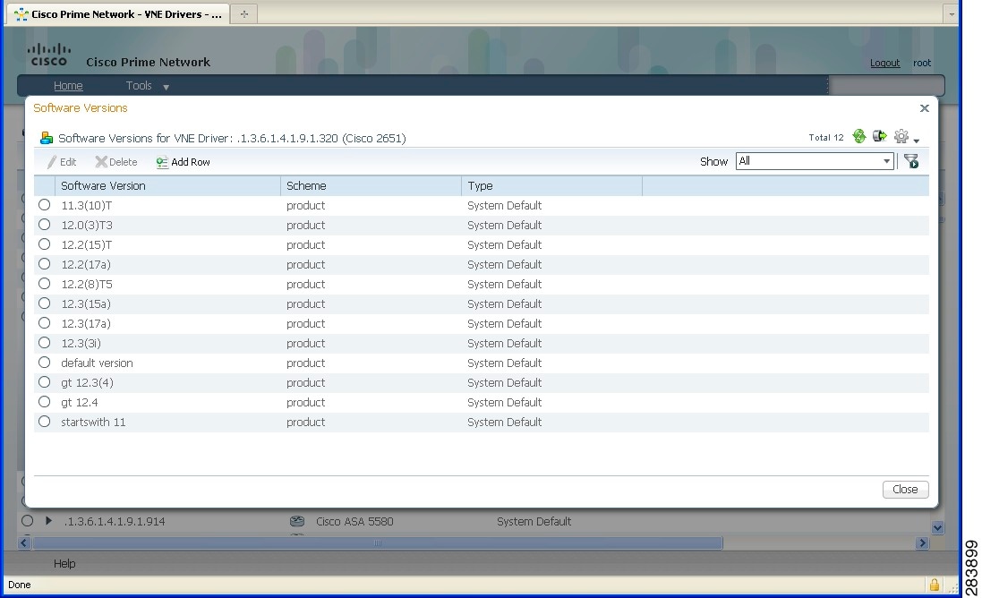
Step 5 Enter the values for the following parameters:
The scheme based on which the VNE is modeled, either Product or IpCore. For more information about schemes, see the Cisco Prime Network 5.0 Administrator Guide. |
|
The already supported software version to be cloned in order to add support for the new software version. |
Step 7 Test the VNE as described in Testing and Certifying VCB Customizations.
Add Support for Additional Modules
These topics explain how to use the Prime Network VCB to enable support for new standard and pluggable modules on developed VNEs and U-VNEs.
If a module does not have “out-of-the-box” support, Prime Network will discover it on a best-effort basis and will generate an informational event with the following description:
“Unsupported module was auto-discovered”
You should validate that all the components of the module were discovered in full. If not, you can add support for the module using the VCB.
Adding Support for a New Standard Module
Module templates are used to enable developed VNEs to recognize new standard modules. Module templates define a set of port layers—from the connector at Layer 0 to encapsulation at Layer 2—that are applicable to a module. Module templates ensure that each port is modeled with the correct port layer information based on the ifType obtained from the SNMP MIB output.
- Obtain the module identifier and research the capabilities of the module. The module identifier can be found in the properties of the event generated when an unsupported module is auto-discovered.
- Identify the appropriate module template. See Module Templates.
To add support for a new standard module:
Step 1 From the Prime Network Administration GUI client, choose Tools > VNE Customization Builder.
Step 2 Choose VNE Customization Builder > Modules. In the Modules page, the Cisco Modules tab is selected by default and all the available Cisco module groups are shown. If you are adding support for a non-Cisco module, click the Non-Cisco Modules tab.
Step 3 Click on a module group to show all the modules for that group.
Step 4 Click on the arrow next to a module to expand its display and see all the port layers supported by that module.
If you want to edit a module, select the radio button to the left of the row and then click the Edit button If you edit a system default module, the value in the Overriding column will change to True . To revert back to the system default values, click Restore .
Step 5 Select the module group under which you want to create the new module. All the modules under the module group you choose are displayed.
Step 6 Click the Add Row button on the taskbar. A new row opens in an editable mode at the end of the modules display area. Enter the value(s) for the following parameters:
Name of the template to be used to enable recognition of the new module. You can select a template from the drop-down list. See Module Templates for information about each template. |
|
The MIB name of the module is usually used as the hardware description. For example, for module .1.3.6.1.4.1.9.12.3.1.9.2.175 (SPA-4XOC48POS/RPR) the hardware description could be cevSpa4pOc48PosSfp. Alternatively, you can use a readable string followed by the mib name, for example, 4 Port OC48 POS SPA (cevSpa4pOc48PosSfp). |
|
The module type can be System Default or User Defined. If you are adding a new module, this field is automatically populated as User Defined and cannot be edited. |
|
Indicates if a system defined module has been modified by the user. |
Step 8 Test the new module. See Testing and Certifying Module Customizations.
Adding Support for a New Pluggable Module
This procedure explains how to add support for a pluggable module. When you add support for a new pluggable module, you do not need to specify a template to use.
Note You cannot edit or delete Prime Network default pluggable modules.
To add support for a new pluggable module:
Step 1 From the Prime Network Administration GUI client, choose Tools > VNE Customization Builder.
Step 2 Choose VNE Customization Builder > Pluggable Modules. The Pluggable Modules tab displays all the pluggable modules in Prime Network VCB.
If you want to edit a module, select the radio button to the left of the row and then click the Edit button
Step 3 Click the Add Row button on the taskbar. A new row opens in an editable mode at the end of the pluggable modules display area. Enter the value(s) of the following parameters:
Name of the new pluggable module.3 This field cannot be empty. |
|
Specifies the media type of the port through which the pluggable module is connected. You can manually enter the values or choose a value from the drop-down list4. |
|
The unique Pluggable Module ID. 1. |
|
Specifies the type of the new pluggable module. Pluggable types are SFP, XFP, X2, and XENPAK. You can manually enter the values or choose the value from the drop-down list. 2 |
|
Specifies whether the pluggable module is user-defined or Prime Network default. This field by default is “User Defined” and is not editable. |
Step 5 Test the new module. For the procedure on testing the VNEs, see Testing and Certifying Module Customizations.
Testing and Certifying VCB Customizations
Testing and certifying ensures that you:
- Do not create unintended or undesired results in your production network
- Do obtain the best possible result, a customization that most closely fits technologies, topologies, and other aspects that you need to model
These topics describe the tests you should perform:
- Preparing to Test Your VCB Customizations
- Testing and Certifying U-VNEs
- Testing and Certifying Module Customizations
- Testing and Certifying Event Customizations
- Troubleshooting VCB Customizations
Preparing to Test Your VCB Customizations
Table 3-3 provides a recommended list of test resources for verifying your customizations. Some of these resources are outside of Prime Network.
In addition, the VCB log file is useful for debugging issues that might occur when you use the VCB.
Use the -logfile option to specify the name of the log file and the -debuglevel option to define the logging level to use. The relevant command is:
vcb mode command [ command args ] -debuglevel INFO -logfile logfilename -user username -password password
When debugging, set the debug level to INFO. The log file is created in the NETWORKHOME /Main/logs directory. Error messages are written to the log file and are displayed on the console.
Creating a U-VNE instance to verify the physical and logical inventory, that events from the device are received, and ensure the U-VNE does not impact VNE performance. |
|
Communicating directly with the device and measuring performance-related issues, such as CPU and memory usage (both with and without the VNE) in various scenarios. |
|
VCB Template Reference, provides the list of technologies and properties that are supported by the template on which the U-VNE is based. Cisco Prime Network 5.0 Supported Cisco VNEs lists the Prime Network supported devices, software versions, modules, and technologies. |
|
Testing and Certifying U-VNEs
After using the VCB to perform device customizations, you must test the VNE or U-VNE to verify that the device and its components can be managed by Prime Network to your satisfaction.To test the results of your VCB commands, we recommend that you add a single instance of the customized VNE to its own AVM in Prime Network.
Examples of the support you should test for include:
We recommend that you record the results of your tests in a compliance report, which certifies the capabilities of the customized VNE. See Preparing Compliance Reports. After you successfully complete the testing process, create additional VNE instances to manage the rest of the devices of this type in the network.
Note When performing the tests described in this section, bear in mind that unlike developed VNEs, U-VNEs are not optimized for a particular device type. The VCB enables you to extend VNEs and create U-VNEs as specified in this document. Other Prime Network features, such as Soft Properties and Command Manager, offer further extensibility to the U-VNE and developed VNE drivers. Prime Network users who need more management capability—or who prefer to have developed VNE drivers for devices that are not already in the Prime Network VNE support scope—can contact their Cisco account representative for any available Cisco Advanced Services alternative.
For details about testing U-VNEs, please see the following sections:
Setting Up the U-VNE Test Environment
Before beginning the testing process, you must ensure that:
- All the mandatory processes—avm11, avm0, and avm100 (only for event support)—are running normally.
- You have access to the device.
- You complete the actions described in Table 3-4 .
Configure the device to send events to the Prime Network server. |
This is required before you test whether Prime Network can receive events from the VNE. |
|
Create an AVM for hosting the VNE instance on which you will perform the tests. |
By isolating the test VNE on its own AVM, you prevent any actions that might impact the functionality of your network. |
|
Measure device performance (such as CPU and memory usage) on the device, with and without the VNE. |
This enables you to determine whether the VNE is placing an unreasonable load on the device. |
|
Fill in the compliance report during testing to track your results against the list of supported technologies and properties outlined in U-VNE Templates. |
Creating a Test AVM and VNE
We recommend that you create an AVM for the sole purpose of hosting the VNE instance on which you will perform the tests described in this chapter. Placing the VNE instance in its own AVM enables you to test your customizations in a safe environment, where the logs and any errors generated by the VNE are isolated from the rest of your network. This enables you to proceed with testing without having your VNE customizations impact the network, until you are satisfied that the customizations function as required.
Testing a single VNE instance also helps you scale a rollout more easily. For example, if you have 100 devices of a certain type that you are introducing to your managed network, first create a single VNE instance on which to test your customizations. After testing is complete, create additional VNEs for the other 99 devices.
AVMs and VNEs can be created in the Prime Network Administration client. For further details about creating an AVM and adding a VNE, see the Cisco Prime Network 5.0 Administrator Guide .
Checking the Communication and Investigation State of the Test Instance
After you create a test instance of the U-VNE, you must verify that Prime Network can communicate with the device (communication state) and that Prime Network can discover the physical and logical inventory of the device (investigation state).
To check the communication and investigation state of the test instance:
Step 1 Log into Prime Network Vision.
Step 2 Choose Network Inventory > Network Elements .
Step 3 Perform a search to locate the device.
Step 4 Check the Communication State column to see the status of the communication between Prime Network and the device:
- If the status is Device Reachable, this indicates that all of the enabled protocols on the device are responding.
- If the status is Device Unreachable, this indicates that at least one of the enabled protocols is not responding. If this occurs, troubleshoot the problem, as described in Device Unreachable.
Step 5 Check the Investigation State column to see how successfully the VNE has modeled the device it represents:
- If the status is Operational, proceed to the next test.
- If the status is Incomplete, this indicates that Prime Network is unable to model all the components in the device. You must investigate further to determine whether the components or properties that cannot be modeled prevent you from using the U-VNE in your network. For troubleshooting details, see Investigation State Not Operational.
Note For more information on troubleshooting VNE modeling, see the Cisco Prime Network 5.0 Administrator Guide.
Measuring Device Performance
We recommend that you use an element manager or similar application to measure CPU and memory usage on the device before you start managing it with the VNE. This provides a baseline for comparison when you later measure the load on the VNE as part of the testing process. You should simulate various scenarios, including those that place heavy loads on the device, so that you can later determine the effect of your VNE customizations on device performance. See Testing CPU and Memory Usage.
Performing the U-VNE Tests
To test and certify U-VNEs, we recommend that you follow these procedures.
1. Preparing Compliance Reports
2. Testing the Physical Inventory
3. Testing the Logical Inventory
4. Testing CPU and Memory Usage
5. Verifying That Prime Network Receives Events from an NE and Generates Tickets
Preparing Compliance Reports
As you complete the tests described in this chapter, we recommend that you capture the results in a compliance report. A compliance report makes it easier for you to evaluate whether the U-VNE suits your needs or whether you will need to try again by cloning from a different device or using a different U-VNE template.
Create a compliance report using the information provided in Cisco Prime Network 5.0 Supported Cisco VNEs (for a U-VNE that was cloned from an existing device family) or U-VNE Templates (for a template-based U-VNE). Use the information to do the following:
1. Copy each technology table to a file (such as a spreadsheet).
2. Remove any columns that describe support for templates other than the one you are using.
3. Add a column for verifying whether each supported property is modeled in Prime Network.
4. Fill out the final column, identifying the supported and unsupported properties.
Assessing a customization requires that you test on a reasonable configuration (test-to-success) and that you evaluate extreme cases (test-to-fail).
Note You cannot use the VCB to change the templates themselves; for example, to support additional CLIs or MIBs or to modify the parsing of the device results.
If you find gaps in the modeling of the U-VNE, you can try using Soft Properties. If you need more management capability or you prefer to have developed VNE drivers for devices that are not already in the Prime Network VNE support scope, contact your Cisco account representative for any available Cisco Advanced Services alternative.
Testing the Physical Inventory
The physical inventory reflects the physical components of the managed device, including its:
- Port Connector—Port details.
- Shelf—Chassis or rack where various types of equipment may be placed or inserted.
- Slot—Details on where the modules are inserted.
- Module—Physical module or adapter card details; hardware description.
Note The list of components that are actually displayed for the U-VNE in the Prime Network client are dependent on the device from which the U-VNE was cloned or on the template that was used to create the U-VNE.
To view the physical inventory:
Step 1 Log into Prime Network Vision.
Step 2 Choose Network Inventory > Network Elements .
Step 3 Perform a search to locate the device.
Step 4 Double-click the device.
Step 5 Expand the Physical Inventory tree node.
Step 6 Compare the physical containment displayed in the Physical Inventory tree with the actual components contained in the device managed by the U-VNE. In particular, make sure that the following information is accurate:
Step 7 Look for signs that the U-VNE does not fully model the device, including:
Step 8 Select each component in the tree, then check the Properties window to verify that the physical inventory includes all the properties that are supported by the U-VNE (as defined in the U-VNE template on which it is based).
Step 9 Record your results in a compliance report. See Preparing Compliance Reports.
Step 10 If there are components or properties that are missing or incomplete, you must decide whether these components or properties prevent you from using the U-VNE in your network:

Tip In the case of a missing property, try adding it using the Soft Property Builder.
- If you need more management capability or you prefer to have developed VNE drivers for devices that are not already in the Prime Network VNE support scope, you can contact your Cisco account representative for any available Cisco Advanced Services alternative.
(The VCB enables you to extend VNEs and create U-VNEs as specified in this chapter. Other Prime Network features, such as Soft Properties and Command Builder, described in separate chapters, offer further extensibility to the U-VNE and developed VNE drivers.)
Testing the Logical Inventory
The logical inventory reflects dynamic data such as configuration data, forwarding, and service-related components that affect traffic handling in the element. The list of components that are actually displayed in the logical inventory are dependent on the technologies supported either the device family from which the U-VNE was cloned or by the template that was used to create the U-VNE.
To view the logical inventory:
Step 1 Log into Prime Network Vision.
Step 2 Choose Network Inventory > Network Elements .
Step 3 Perform a search to locate the device.
Step 4 Double-click the device.
Step 5 Expand the Logical Inventory tree node.
Step 6 Compare the information displayed in the Logical Inventory tree with the actual technologies supported by the U-VNE, as defined by the template on which the U-VNE is based. See U-VNE Templates.
Step 7 Select each component in the tree, then check the Properties view to verify that the logical inventory includes all the properties that are supported by the U-VNE (as defined in the U-VNE template on which it is based).
Verify the IP interfaces by querying the device for its list of IP interfaces and verifying that all of them appear under IP Flow Points. Verify that all the IP interfaces configured on the device appear in the IP Interfaces tab under Routing Entity.
Step 8 Record your results in a compliance report. See Preparing Compliance Reports.
Step 9 If any technologies or properties are missing or incomplete, you must investigate further to determine whether these technologies or properties prevent you from using the U-VNE in your network:
- If you determine that the device can be managed successfully by Prime Network without the unsupported technology or property, proceed to the next test.
- If you need more management capability or you prefer to have developed VNE drivers for devices that are not already in the Prime Network VNE support scope, you can contact your Cisco account representative for any available Cisco Advanced Services alternative.
Testing CPU and Memory Usage
Note Ensure that you perform both positive testing (on a reasonable configuration) and negative testing (on simulations of expected network scenarios).
In addition to verifying how well the U-VNE models the device, we recommend that you measure the CPU and memory usage demands placed by the U-VNE on the device. During test preparation, before adding the VNE instance, you measured CPU and memory usage on the NE; (see Measuring Device Performance). Now, compare the usage on the NE against the usage for the VNE instance on the Prime Network AVM and unit as follows:
- To view CPU usage, look at the properties of the device in the Inventory window.
- To monitor additional information, such as memory usage, use the Prime Network diagnostic client. To access the diagnostic client, enter the following address in your web browser (the username is normally admin; you will have to get the password from your system administrator):
Verifying That Prime Network Receives Events from an NE and Generates Tickets
This topic provides steps for verifying that Prime Network receives events from an NE and that the VNE driver parses the events correctly, generating tickets if the events are ticketable.
Note Event parsing depends on the completeness and correctness of the modeling. Parsing BGP events, for example, depends on BGP being modeled correctly in the inventory.
Make sure that you have configured the device to send events to the Prime Network server and created a Link Down event.
To check for events from the NE:
Step 1 Log into Prime Network Vision.
Step 2 Add the device to a map.
Step 3 Right-click on the device in the map and select Filter Tickets. The tickets pane below the map will show the tickets for the selected device.
Step 4 Check whether the Link Down event that you generated during your test preparations appears in the table.
Step 5 Generate additional events from the device, then see if they appear in the events table.
Step 6 If the events do not appear in the events table, proceed as follows:
- Check for mistakes in the device configuration.
- Use an external tool, such as a MIB browser, to determine whether events are being sent by the device.
- Troubleshoot event customization, as described in Customizing Events.
Testing and Certifying Module Customizations
First perform a static test of the module, using the vcb view module command. If the module is not correctly configured, delete it and add the module again.
After verifying the module statically, set up your test environment just as you would for testing device customization—see Setting Up the U-VNE Test Environment. Then view the physical inventory for your U-VNE test instance as follows.
Step 1 Launch Prime Network Vision.
Step 2 Add the containing device to a map.
Step 3 Double-click the device.
Step 4 Expand the Physical Inventory tree node.
Step 5 Confirm the correctness of the following for the module:
Step 6 Move customizations into production during a maintenance window. See Testing and Certifying U-VNEs.
Testing and Certifying Event Customizations
It is recommended that you test and certify event customizations in your lab before moving them to production:
To receive events from a device, you must configure the device with the details of the Prime Network server. For example, use the following commands for devices running Cisco IOS or Catalyst OS software:
logging source-interface Loopback0
A similar set of commands should be used for devices belonging to other manufacturers.
These commands enable the device to send traps to the specified gateway IP over port 162. Therefore, port 162 must be enabled to receive traps from the device. In addition, you must reserve port 1162 for the general trap processing by the Prime Network server. This task is handled by the AVM 100 process.
Step 1 Send an event from an NE or from a simulator. Open Prime Network Events and verify that:
– Prime Network recognizes and processes the event
– Event parameters—type, subtype, severity, and so on—are as expected
– Unique ID is appended to source ID (ManagedElement)
After you complete the tests, move the customization to production and test there as well; see Testing and Certifying Event Customizations.
Troubleshooting VCB Customizations
This section describes basic troubleshooting procedures to perform when Prime Network cannot communicate with a U-VNE, and includes the following topics:
Device Unreachable
If you cannot communicate with a U-VNE, try the following:
- Launch Prime Network Administration and verify the Admin Status and Operational Status of the VNE. The Admin Status should be Enabled and the Operational Status should be Up.
- Verify that you are using the correct SNMP and Telnet credentials for the device.
- Ping the device from the Prime Network server.
Note For more information, see the Cisco Prime Network 5.0 Administrator Guide.
Investigation State Not Operational
If the investigation state of the U-VNE is any value other than Operational, perform the actions described in the following table.
The U-VNE is encountering a problem, such as an exception caused by a particular discovery command or an unsupported module. |
Examine the AVM log for messages about:
Note For more information, see Prime Network Logs in the Cisco Prime Network 5.0 Administrator Guide. Check Prime Network Vision or Events for an “unsupported module” system event. |
|
Use the vcb sitechanges view command to verify that the U-VNE registrations were created properly. In particular, make sure that you used the correct sysObjectID for this device type when using the VCB to create the U-VNE-driver. If the sysObjectID is not correct:
|
Log Entry for Unsupported Module
The log entry for an unsupported module looks like this:
ERROR [07 07 2010 17:07:47.810 IST] - PhysicalCommandHandler.isEntitySupported - 192.168.20.1 can't create module with entry

value spec/physical/modules/.1.3.6.1.4.1.9.12.3.1.9.29.118.1/loaders will use default module loader
If you have an unsupported module, your choices are to either use the VCB to add the module (see Adding Support for a New Pluggable Module), or manage the device in Prime Network without managing that particular module.
Deploying VCB Customizations to Your Production Environment
Tip Always perform customization in a maintenance window.
During a maintenance window, recreate the extensions that you have tested and certified in your lab by following this procedure:
Viewing Existing VCB Customizations in the Registry
To view registry changes to the site.xml file made with the VCB, enter the following command:
vcb sitechanges view -user username -password password
Here is an example of the vcb sitechanges view command output; this examples shows customizations that were made, including some event patterns, event parsing rules, and events.
# [~/Main/registry/ConfigurationFiles]%
vcb sitechanges view -user
username
-password
password
>>>>>>>>>>>>>>>>>>>>>Event Pattern<<<<<<<<<<<<<<<<<<<<<<<<<
Hive Name:cisco-syslog-ipcore-parsing-rules
Group: cisco-syslog-ipcore-parsing-rules
Repository: cisco-syslog-repository
Repository: cisco-syslog-repository
Hive Name:cisco-trap-product-parsing-rules
Group: cisco-trap-product-parsing-rules
Rule Name: STACKWISE-MEMBER-STATUS
Repository: cisco-trap-repository
>>>>>>>>>>>>>>>>>>>>>Event Parsing Rules<<<<<<<<<<<<<<<<<<<<<<<<<
Hive Name:cisco-trap-repository
--------------------------------------------------------------------
--------------------------------------------------------------------
STACKWISE-MEMBER-STATUS STACKWISE-MEMBER-STATUS
--------------------------------------------------------------------
Hive Name:cisco-syslog-repository
--------------------------------------------------------------
--------------------------------------------------------------
--------------------------------------------------------------
>>>>>>>>>>>>>>>>>>>>>UVne<<<<<<<<<<<<<<<<<<<<<<<<<
>>>>>>>>>>>>>>>>>>>>>Event<<<<<<<<<<<<<<<<<<<<<<<<<
Event Name: stackwise status trap
Short Description: Stack Member Removed
Short Description: Stack New Member
Event Name: DWDM fatal error 2 syslog
Subtype: DWDM fatal error 2 syslog
Short Description: DWDM fatal error with reason and error number
Exporting VCB Customizations to Another Gateway (GUI)
You can export your VCB customizations and then import them to another Prime Network gateway. During export, all customizations in the registry will be exported, including all user-defined items and all system default overrides.
Step 1 In the VCB tool, click Export Customization . The customizations are exported from site.xml to a VCB command script file, VcbImportCommands.sh, located in NETWORKHOME /Main.
Importing VCB Customizations from Another Gateway (GUI)
Step 1 In the VCB tool, click Import Customization .
Step 2 Select the VcbImportCommands.sh file to be imported. The full script is displayed in the Import Customizations dialog.
Step 3 Optional. Review the script and remove commands that you do not want to import. Click Next .
Step 4 Enter the required credentials, as follows:
The username and password used to access Prime Network components, including the gateway. |
|
The username and password used when logging into the Prime Network GUI. |
Step 5 Click Next . The import process begins. When it is complete, you will receive confirmation and any errors that occur during the execution will be displayed.
Step 6 Check that the imported customizations appear in the VCB tool.
Importing VCB Registry Customizations (CLI)
To import VCB registry customizations:
Step 1 After you export registry changes, copy the VcbImportCommands.sh file to the NETWORKHOME/Main folder on the Prime Network gateway on which you want to import the customizations.
Step 2 (Optional) Edit the VcbImportCommands.sh file and delete any customizations that you do not want to import. The commands of interest in the file start with $VCBPATH as shown in this example:
$VCBPATH eventpattern add -rulename L2-DWDM-3-FATAL_2
-group cisco-syslog-ipcore-parsing-rules -repository cisco-router-iox-syslog-repository -user $USER -password $PASS >> "$VCT_IMPORT_SCRIPT_LOG"
Step 3 Change permissions on the script to ensure that it is executable, by entering a command such as this one:
chmod 755 VcbImportCommands.sh
Step 4 Run the script from the NETWORKHOME/Main folder, by entering this command:
Deleting VNE Customizations from the Registry
These topics describe how to roll back a registry configuration to its original settings, and how to completely delete customizations from the registry.
Customizations using the VCB affect VNE drivers and update the Prime Network registry in a safe manner. The VCB enables you to roll back easily; you can remove:
- All VCB customizations with one command, restoring your system to a factory-defined state.
- Selective VCB customizations, using one command per customization that you want to remove.
Because VCB customizations are carried forward during an upgrade to a new version of Prime Network, your customizations continue to override any new or updated VNE drivers or newly supported events and modules. The ability to remove changes selectively enables you to discontinue particular overrides only and take advantage of any newly added support.
Step 1 Create a script file,VcbDeleteCommands.sh, in NETWORKHOME /Main by entering this command:
vcb sitechanges delete -user username -password password
Step 2 (Optional) To retain any specific customizations, edit the VcbDeleteCommands.sh file and remove any line that deletes a customization that you want to keep. The commands of interest in the file start with $VCBPATH as shown in this example:
$VCBPATH eventpattern delete -group cisco-syslog-ipcore-parsing-rules -patternid 5001 -user $USER -password $PASS >> "$VCT_IMPORT_SCRIPT_LOG"
Step 3 Change permissions on the script to ensure that it is executable, by entering a command such as this one:
chmod 755 VcbDeleteCommands.sh
Step 4 Run the script from the NETWORKHOME /Main folder, by entering this command:
VcbDeleteCommands.sh $username $password
 Feedback