Carrier Routing System 4-Slot Line Card Chassis Unpacking, Moving, and Securing Guide
This guide provides instructions for unpacking the Cisco CRS Carrier Routing System 4-Slot Line Card Chassis (LCC) and its components, moving the chassis to its permanent location, and mounting and securing the chassis in a rack. The companion document to this guide is the Cisco CRS Carrier Routing System 4-Slot Line Card Chassis Site Planning Guide, which describes how to plan and prepare your site facilities for the installation of a Cisco CRS 4-slot LCC.
About the Cisco CRS Carrier Routing System Line Card Chassis
The introduction of the Cisco CRS Carrier Routing System 4-Slot LCC allows service providers to utilize the power and features of a Cisco CRS chassis, but without the space and power requirements associated with the larger (16-slot and 8-slot) versions of the chassis. The Cisco CRS 4-slot LCC is a mechanical enclosure that contains four slots for modular services cards (MSCs) and associated physical layer interface modules (PLIMs), and four slots for the switch fabric.
The chassis is installed in a standard external rack and contains its own power and cooling systems. The chassis also contains route processor (RP) or performance route processor (PRP) cards that perform routing-protocol calculations. The RPs or PRPs distribute forwarding tables to the modular services cards (MSCs), provide a control path to each MSC for system monitoring functions, and contain hard disks for system and error logging. RPs and PRPs plug into two dedicated slots in the 4-slot LCC.
The Cisco CRS 4-slot LCC has four MSC slots, each with a capacity of 40 gigabits per second (Gbps) ingress and 40 Gbps egress, for a total routing capacity of 320 Gbps per chassis. The router is built around a scalable, distributed three-stage Benes switch fabric and a variety of data interfaces. The data interfaces are contained on physical layer interface modules (PLIMs) that are mated in the LCC to an associated MSC. MSCs, which are sometimes referred to as line cards, are cross-connected to each other through the switch fabric.
Overview of Unpacking, Moving, and Securing the Chassis
The following table provides an overview of the tasks required to get the Cisco CRS 4-Slot LCC from the shipping bay to the installation location and mounted into its rack.
Procedure
| Command or Action | Purpose | |||
|---|---|---|---|---|
| Step 1 |
Move the rack into the installation location for the Cisco CRS 4-slot chassis (see the Preparing the Rack for Chassis Installation section). |
See the Cisco CRS Carrier Routing System 4-Slot Line Card Chassis Site Planning Guide for important information regarding site preparation. |
||
| Step 2 |
(Optional) Install the horizontal mounting rails to the rack (see the Installing the Horizontal Mounting Rails in the Rack section. |
Horizontal mounting rails are an optional accessory (field replaceable unit); you must order them separately. |
||
| Step 3 |
Secure the rack to the floor (see the Preparing the Rack for Chassis Installation section). |
Ensure that the rack is properly grounded in accordance with electrical grounding requirements. |
||
| Step 4 |
Use a fork lift or scissor lift to transport the 4-slot chassis from the loading dock to the staging area. |
— |
||
| Step 5 |
In the staging area, remove the packaging from the chassis, leaving the chassis attached to the pallet (see the Removing the Packaging from the Chassis section). |
For safety and stability, it is important to move the chassis while it is still mounted on the pallet. |
||
| Step 6 |
Move the chassis and pallet to the room in which it will be installed (see the Moving the Cisco CRS 4-Slot Line Card Chassis to Its Permanent Location section). |
Make sure that there are no impediments to moving the chassis through the facility to its installation location. To ensure that the chassis has proper access to the installation location, see the Cisco CRS Carrier Routing System 4-Slot Line Card Chassis Site Planning Guide . |
||
| Step 7 |
Remove the support brackets that secure the chassis to the pallet (see the Removing the Pallet Chassis Support Brackets section). |
Be sure to reinsert the screws removed from the chassis back into the chassis. |
||
| Step 8 |
Then transfer the chassis from the pallet to a scissor lift or other suitable lifting device (see the Transferring the Chassis to a Lifting Device section). |
The scissor lift should have a lifting capacity exceeding 500 lb (226.8 kg).
|
||
| Step 9 |
Mount the chassis into the rack (see the Securing the Chassis in the Rack section). |
— |
||
| Step 10 |
Secure the front of the chassis to the rack with the vertical mounting brackets. |
There are 12 screws per side. |
||
| Step 11 |
Optional: Attach the rear vertical mounting brackets to the chassis (see the Attaching the Rear Vertical Mounting Brackets section). |
The rear mounting bracket is not required to safely secure the Cisco 4-slot LCC in the rack. However, the Cisco CRS 4-slot LCC ships with rear mounting brackets so that customers may secure the rear of the chassis to a rack if they wish. |
||
| Step 12 |
Optional: Secure the rear of the chassis to the rack with the vertical mounting brackets (see the Securing the Rear Mounting Brackets to the Rack section). |
— |
||
| Step 13 |
Proceed with installing the Cisco CRS 4-slot LCC. |
See the Cisco CRS Carrier Routing System 4-Slot Line Card Chassis Installation Guide . |
Shipping Carton and Pallet Specifications
The Cisco CRS 4-slot LCC is shipped in a double-wall carton on a standard shipping pallet. The shipping package for the Cisco CRS 4-slot LCC is engineered to reduce the potential of product damage associated with routine material handling experienced during shipment.
 Tip |
Always transport the chassis in its original packaging and make sure that the system is transported and stored in an upright position. |
If you plan to store system components before the installation, be sure to store the components carefully and in their original shipping containers to prevent accidental damage. Failure to do so may result in damage to the router or degradation of its performance. Also, do not remove the router from its shipping container until you are ready to install it. Keep the router in the shipping container until you have determined where you will install it.
Tip |
Inspect all items for shipping damage; if any damage is evident, immediately contact a Cisco customer service representative. |
A newly received Cisco CRS 4-slot LCC in its shipping carton and on a pallet has the following physical characteristics:
- Weight:
- CRS-4 spare chassis: 225.8 lb (102.4 kg)
- CRS-4 as-shipped, minimally configured by customer: 301.8 lb (136.9 kg)
- CRS-4 as-shipped, maximum configuration by customer: 361 lb (163.8 kg)
- Pallet length: 39.75 inches (100.97 cm)
- Pallet width: 24.5 inches (62.23 cm)
- Pallet height:
- From floor to top of complete package (with box): 42 inches (106.68 cm)
- From floor to top of wood deck (carton removed): 7.5 inches (19.05 cm)
 Caution |
Do not stack the Cisco CRS 4-slot LCC shipping cartons, because serious damage to the system can occur. |
Shipping and Receiving Considerations
As you plan for your shipping and receiving needs, you should also consider the following:
-
Transporting the Cisco CRS 4-slot LCC from the loading dock and staging area to the freight elevator:
- Are the dock ramps wide enough to accommodate the Cisco CRS 4-slot LCC shipping cartons?
- Are there any ceiling limitations or obstructions (such as low-hanging pipes) that would obstruct the Cisco CRS 4-slot LCC shipping cartons as they are being transported to the freight elevator?
- Clear the area where you will unpack the components.
- Understand the sequence in which you will unpack and install the components.
Electrical Safety
The field-replaceable units (FRUs) in the LCC offer online insertion and removal (OIR) capability, which means that a FRU is hot swappable and can be removed and replaced while the system is operating without presenting an electrical hazard or causing damage to the system.
The following FRUs feature online OIR:
- Modular service cards (MSCs)
- Forwarding processor (FP) cards
- Physical layer interface modules (PLIMs)
- Route processors (RPs or PRPs)—only when two RPs or two PRPs are installed in the chassis
- Switch fabric cards (SFCs)
- Air filter
 Note |
For details on installing and removing components, see the Cisco CRS Carrier Routing System 4-Slot Line Card Chassis Installation Guide. |
Electrical Equipment
Working with electrical equipment can be hazardous. Three types of potential hazards are addressed in this section:
- Potential electrical accidents involving people and equipment
- Potential electrical accidents involving equipment only
- Potential electrical accidents involving your installation site
Electric Shock Hazard Guideline
Use these guidelines if an electrical accident occurs while working with any electrical equipment.
- Disconnect the power to the system. Never assume that power has been disconnected from a circuit; always check.
Caution |
Before assisting an injured person, make sure that there is no possibility of electrical shock or other potential hazard to yourself. |
- Send another person to get medical aid; otherwise, assess the condition of the victim and then call for help.
- Determine if the person needs rescue breathing or external cardiac compressions, then take appropriate action.
Equipment Hazards Guidelines
Use these guidelines when working with equipment you want to install:
- Disconnect all power and external cables before installing or removing a chassis.
- Do not assume that power has been disconnected from a circuit; always check.
- Do not perform any action that creates a potential hazard to people or makes the equipment unsafe.
- Do not install equipment that appears damaged.
-
Carefully examine your work area for possible hazards such as the following:
- Moist floors
- Ungrounded power extension cables
- Missing safety grounds
Installation Hazards Guidelines
Use these guidelines when working with equipment that is disconnected from a power source, but is still connected to telephone or network wiring.
- Do not install telephone wiring during a lightning storm.
- Do not install telephone jacks in wet locations unless the jack is specifically designed for wet locations.
- Do not touch uninsulated telephone wires or terminals unless you are sure that the telephone line has been disconnected at the network interface.
- Use caution when installing or modifying telephone lines.
Preparing the Rack for Chassis Installation
Install the Cisco CRS 4-Slot LCC into a 30-inch standard rack with 22.8-inch pitch standard horizontal mounting rails.
For more detailed information about rack requirements for the Cisco CRS 4-slot LCC, see the “Rack-Mounting Planning Guidelines” section in Chapter 3 of the Cisco CRS Carrier Routing System 4-Slot Line Card Chassis Site Planning Guide .
Before you move the chassis or mount the chassis into the rack, we recommend that you do the following:
SUMMARY STEPS
- Place the rack into the location to install the Cisco CRS 4-slot LCC.
- Secure the rack to the floor.
DETAILED STEPS
| Step 1 |
Place the rack into the location to install the Cisco CRS 4-slot LCC. |
||||
| Step 2 |
Secure the rack to the floor.
To bolt the rack to the floor, a floor bolt kit (also called an anchor embedment kit ) is required. For information on bolting the rack to the floor, consult a company that specializes in floor mounting kits.
|
Planning for Floor-Mounting Holes
When planning for the floor-mounting holes, take these guidelines into account for Enclosure Systems Worldwide (ESW) 27 racks:
- Chassis floor mounting L-brackets:
20.1 inches (51.0 cm) wide x 31.6 inches (80.3 cm) deep
- Internal frame holes are as follows:
17.625 inches (44.77 cm wide) x 21 inches (53.34 cm) deep
For all other racks, check with the rack manufacturer.
Installing the Horizontal Mounting Rails in the Rack
The Cisco CRS 4-slot LCC offers horizontal mounting rails as an optional accessory or FRU (field replaceable unit); you must order them separately. The horizontal mounting rails provide a stable platform for the weight of the chassis in a rack.
The horizontal mounting rails consist of two rails and two width adjustment brackets (see Figure 1). Attach a width adjustment bracket to each horizontal mounting rail so that you can then secure the horizontal mounting rails to the rack.
Prerequisites
Before you start to install the horizontal mounting brackets, verify that the distance between the outside edges of the rack’s vertical mounting brackets does not exceed 20 inches. If that distance exceeds 20 inches, adjust the vertical mounting brackets accordingly.
Required Tools and Equipment
You need the following tools and parts to perform this task:
- Number 2 Phillips screwdriver
- Horizontal mounting rails (Cisco product number: CRS-4-HRZ-RAILS(=))
Steps
To install the horizontal mounting rails in the rack, follow these steps:
Procedure
| Step 1 |
Determine the height at which you want the Cisco CRS 4-slot LCC to be installed into the rack. |
||||||
| Step 2 |
Using a Number 2 Phillips screwdriver and the M4 screws included in the kit, loosely attach one width adjustment bracket to each horizontal mounting rail so that the distance of the combined rail and width adjustment bracket equals the distance between the outside edges of the rack’s vertical mounting brackets. 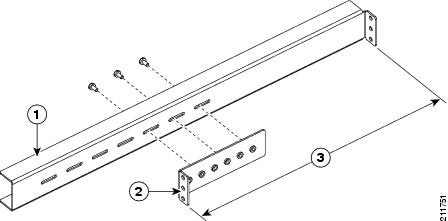
|
||||||
| Step 3 |
Using the screws appropriate for the rack (which are supplied by the rack manufacturer), secure the horizontal mounting rails to the rack’s vertical mounting brackets through the rail’s outward-facing edges.
|
||||||
| Step 4 |
Using the Number 2 Phillips screwdriver, tighten the three M-4 Phillips screws that attaches each width adjustment bracket to its corresponding horizontal mounting rail. The rack is now ready for you to lift the Cisco CRS 4-slot LCC onto the horizontal mounting rails (see the Securing the Chassis in the Rack section). |
Chassis Packaging Overview
The Cisco CRS 4-slot LCC arrives packaged on several pallets (the number of pallets depends on the options you ordered) with each package containing a label that describes the contents. The primary system pallet (Crate 1) contains the chassis itself encased in a polyethylene bag and covered with a corrugated primary shipper packing crate held together with plastic bands.
The chassis is shipped with the air filter, fan tray, powershelf, and power supplies already installed. If ordered with the system, the modular services card (MSC), physical layer interface module (PLIM), switch fabric card (SFC), and route processor (RP or PRP) cards are installed as well.
The primary system pallet also contains the rear mounting brackets (in their own box) and an accessory carton with the front doors and inlet grille (if ordered), cables, and documentation.
|
Component |
Cisco Product IDs |
|---|---|
|
AC powershelf |
CRS-4-AC-SHELF |
|
AC power supply |
CRS-4-AC-SUPPLY |
|
DC power input module |
CRS-4-DC-PIM |
|
DC power input shelf |
CRS-4-DC-INPUT |
|
DC power supply |
CRS-4-DC-SUPPLY |
|
Air filter |
CRS-4-FILTER |
|
Chassis |
CRS-4-CH |
|
Door kit |
CRS-4-DOOR-KIT |
|
Fan trays |
CRS-4-FAN-TR |
|
MSC impedance carrier |
CRS-MSC-IMPEDANCE |
|
PLIM impedance carrier |
CRS-INT-IMPEDANCE |
|
RP card impedance carrier |
CRS-4-RP-BLANK |
|
Modular services cards (MSCs) Refer to the product data sheets for ordering details. |
CRS-MSC, CRS-MSC-B, or CRS-MSC-140G |
|
Forwarding processors (FPs) Refer to the product data sheets for ordering details. |
CRS-FP40, orCRS-FP-140G |
|
Route processor (RP) Performance route processor (PRP) |
CRS-8-RP or CRS-8-PRP-6GCRS-8-PRP-12G |
|
Switch fabric card |
CRS-4-FC/S or CRS-4-FC140/S |
|
Switch fabric card blank |
CRS-4-FC-BLANK |
For complete details on the contents of each pallet, see the shipping and parts identification label on the pallet.
Unpacking the Cisco CRS 4-Slot Line Card Chassis
The packaging materials for the Cisco CRS 4-slot LCC include the following:
- Pallet
- Container box
- Box that contains the rear vertical mounting brackets
- Accessories box
- Cardboard pad
The container box slides over the chassis, which fits snugly over the pallet (see the following figure). The following table lists the items you need to unpack the Cisco CRS 4-slot LCC:
|
Tools |
Purpose |
|---|---|
|
Number 2 Phillips screwdriver |
To remove the screws that secure the support brackets to the chassis. |
|
9/16 inch (15 mm) socket wrench |
To remove the bolts that secure the support brackets to the pallet. |
|
Scissors or wire cutters |
To cut the packing straps. |
|
ESD-preventive wrist strap |
To prevent the electrostatic discharge (ESD) damage. |
|
Antistatic mat or bag |
To protect boards. |
Removing the Packaging from the Chassis
To remove the packaging from the CRS 4-slot LCC, follow these steps:
SUMMARY STEPS
- Using scissors or wire cutters, cut off the three plastic bands around the container package.
- Open the top of the package and remove the topmost box, which contains the rear vertical mounting brackets.
- Remove and open the accessory carton.
- Remove the contents and carefully set them aside.
- Remove the cardboard pad that sits on top of the chassis.
- Lift up the container box and remove it.
DETAILED STEPS
| Step 1 |
Using scissors or wire cutters, cut off the three plastic bands around the container package. The figure below shows how the Cisco CRS 4-slot LCC is packaged. 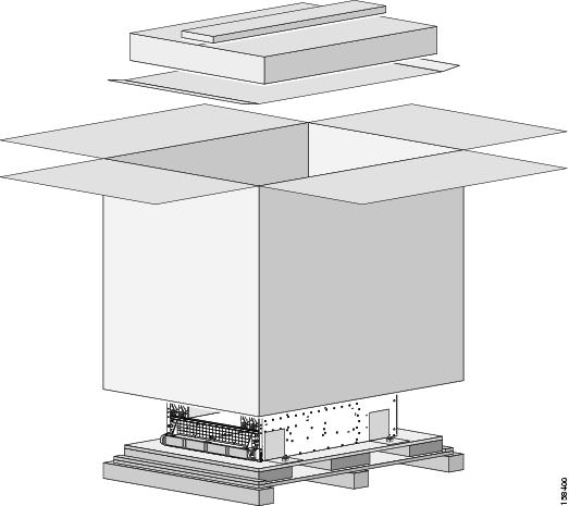 |
| Step 2 |
Open the top of the package and remove the topmost box, which contains the rear vertical mounting brackets. |
| Step 3 |
Remove and open the accessory carton. The contents of the accessory carton are bezel cover, inlet grille, front doors, cables, and cable accessories. |
| Step 4 |
Remove the contents and carefully set them aside. |
| Step 5 |
Remove the cardboard pad that sits on top of the chassis. |
| Step 6 |
Lift up the container box and remove it. |
What to do next
The chassis is now ready to be moved to its permanent location.
Moving the Cisco CRS 4-Slot Line Card Chassis to Its Permanent Location
This section describes the procedures required to move the Cisco CRS 4-Slot LCC in its rack to where it will permanently reside in your facility.
Tip |
The installation of a Cisco CRS 4-Slot LCC may require space, floor loading, power, and cooling modifications to your facility. Therefore, you should plan the site well in advance of the scheduled delivery of the system. See the Cisco CRS Carrier Routing System Line Card Chassis Site Planning Guide . |
Considerations Before Moving the Cisco CRS 4-Slot Line Card Chassis
Before you attempt to move the chassis from the loading dock to the installation site, we recommend that you inspect the proposed transport route, note any areas of concern, and answer the following questions. Depending on the complexity and length of the transport route, it might be useful to create a diagram of the route you plan to take from the loading dock to the installation site.
Note |
We recommend that at least two people move the chassis from the shipping dock to the installation site. |
We also recommend that you leave the chassis attached to its pallet for moving.
When you inspect the proposed transport route, answer the following questions:
- What type of moving device will be used to move the chassis from the loading dock or staging area to the installation site (for example, pallet jack, forklift, or scissor lift)?
- Are all doorways and hallways wide and tall enough for the moving device and the system components?
- Are there any corners in the route to the installation site? Are the corners wide enough to accommodate the moving device and the chassis?
Note |
The Cisco CRS 4-slot LCC needs an aisle of approximately 60 inches (152.4 cm) in width to be turned while on a fork lift. |
- Can elevators support the weight of the system components and the moving device? Are the elevators tall and wide enough?
- Are there any ramps over which the components must be moved? Are ramp inclines within the allowable tolerances? For guidelines, see the Ramp Incline Tolerances section.
- Are there any obstacles in the way that need to be moved (for example, boxes or equipment in hallways, hanging wires, and so on)?
Caution |
If the route to the installation site has any ramps, you must use a moving device other than a scissor lift to move the chassis over the ramps. You can then transfer the chassis onto a scissor lift for installation.Leave the impedance carriers in place in empty card slots while you move the chassis or install it in the rack. The impedance carriers provide support to keep the chassis square during movement and installation. |
Ramp Incline Tolerances
The ramp incline tolerances for moving the Cisco CRS 4-slot LCC are as follows:
- 1:12 or 1 inch of rise per 12 inches (30.5 cm) of run (1:6 for existing ramps).
- Maximum rise for any run is 30 inches (76 cm).
-
Maximum ramp angle is 10°.
- Exception: A ramp with a slope no greater than 1:6 for a run not to exceed 2 feet (61 cm).
Verifying the Installation Floor Plan
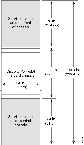
The floor plan for the Cisco CRS 4-slot LCC must include enough space to install the chassis in the equipment rack and allow sufficient airflow for the system. The floor plan must also provide enough room to access chassis components for maintenance (for example, to remove fan trays, power modules, cables, and air filters).
The following figure shows a top view of the footprint required for installation (with optional front doors installed).
Note |
When installing or moving the chassis, the required service access area in front of the chassis may be more than the minimum of 36 inches (91.4 cm) specified in the figure below, depending on what type of lifting device is used.For chassis installation, make sure that enough room exists in front of the chassis to accommodate installation personnel and the scissor lift (or other lifting device) used to hold the chassis in the rack while it is bolted to the rack. |
Moving the Chassis to the Installation Site
This section describes how to move the unpacked LCC. The LCC is shipped with the front vertical mounting brackets preinstalled for attaching the chassis to the rack. For stability and support, you must leave the mounting brackets installed when you move the chassis.
Note |
The chassis is shipped with impedance carriers installed over all slots. We recommend leaving these in place to maintain chassis stiffness and integrity during moving. |
Before moving the chassis:
- Installation location must be ready to receive the chassis (as described in the Preparing the Rack for Chassis Installation section).
- Packaging should be removed, while leaving the chassis firmly secured to the pallet (as described in the Unpacking the Cisco CRS 4-Slot Line Card Chassis section).
- Obstacles or other impediments to moving the chassis should be understood and removed (as described in the Considerations Before Moving the Cisco CRS 4-Slot Line Card Chassis section).
- Impediments should be removed before moving the chassis through the facility to its installation location. To ensure that the chassis has proper access to the installation location, see the Cisco CRS Carrier Routing System 4-Slot Line Card Chassis Site Planning Guide.
Lifting Guidelines
A fully configured LCC weighs approximately 361 lb. (163.7 kg). Before installing the chassis, ensure that your site is properly prepared so that you can avoid having to move the chassis later to accommodate power source and network connections.
Each time you lift any heavy assembly, refer to these lifting guidelines:
- Never attempt to lift an object that might be too heavy for you to lift by yourself.
- Have a second person available to help lift the assembly.
- Ensure that your footing is solid; balance the weight of the object between your feet.
- Lift the assembly slowly; never move suddenly or twist your body as you lift.
- Keep your back straight and lift with your legs, not your back.
- If you must bend down to lift the assembly, bend at the knees, not at the waist, to reduce the strain on your lower back muscle.
- Always disconnect the power source and unplug all power cables before lifting, moving, or working on the chassis.
Moving the Chassis
To move the Cisco CRS 4-slot chassis to its installation location, follow these steps:
SUMMARY STEPS
- Make sure that the forklift or scissor lift is in the correct configuration to move the Cisco CRS 4-slot LCC.
- With the chassis still attached to the pallet, move the chassis to its installation location.
DETAILED STEPS
| Step 1 |
Make sure that the forklift or scissor lift is in the correct configuration to move the Cisco CRS 4-slot LCC. |
||
| Step 2 |
With the chassis still attached to the pallet, move the chassis to its installation location.
|
What to do next
After moving the chassis to the room or area where you will install it, you can prepare to mount the chassis into the rack, which includes the following procedures:
- Removing the chassis support brackets
- Transferring the chassis to a lifting device
- Securing the chassis in the rack
Removing the Pallet Chassis Support Brackets
In this procedure, you remove the support brackets that secure the chassis to the pallet.
Note |
Do not remove the chassis support brackets until you are ready to install the chassis. |
Caution |
Exercise extreme caution during this procedure. The chassis is unstable when not secured to the pallet or rack. The chassis should always remain upright and should not be bumped or dropped. |
To remove the chassis support brackets, follow these steps:
SUMMARY STEPS
- With a wrench or socket wrench, remove the 9/16-inch (15-mm) bolts that secure each support bracket to the pallet.
- Using a medium (number 2) Phillips screwdriver, remove the three Phillips head screws that secure each support bracket to the chassis; then set the screws aside.
- Set the support brackets aside.
- Reinsert the six screws into the chassis (three per side from the front right and left support brackets) because they are necessary to attach the front mounting brackets.
DETAILED STEPS
| Step 1 |
With a wrench or socket wrench, remove the 9/16-inch (15-mm) bolts that secure each support bracket to the pallet. |
| Step 2 |
Using a medium (number 2) Phillips screwdriver, remove the three Phillips head screws that secure each support bracket to the chassis; then set the screws aside. |
| Step 3 |
Set the support brackets aside. |
| Step 4 |
Reinsert the six screws into the chassis (three per side from the front right and left support brackets) because they are necessary to attach the front mounting brackets. |
What to do next
You are now ready to move the chassis from the pallet to a lifting device, as described in the next section.
Transferring the Chassis to a Lifting Device
Caution |
Because of the chassis weight (about 255 lb [115.2 kg] with fans, power supplies, and impedance carriers; about 361 lb [163.7 kg] with MSC's, PLIM's, switch fabric, and route processor boards installed as well), you should not attempt to move or lift it without a mechanical lifting device. The lifting device should have a lifting capacity exceeding 500 lb (226.8 kg). |
To transfer the Cisco CRS 4-slot chassis from the pallet to a lifting device, follow these steps:
SUMMARY STEPS
- Place the mechanical lifting device in front of the chassis and center the lifting device relative to the chassis.
- Position the lifting surface of the device so that it is flush with the bottom of the chassis (see the figure below).
- Place a piece of cardboard on the surface of the lift.
- With two people grasping the chassis, slide the chassis carefully from the pallet on top of the cardboard and onto the lift (see the following figure).
DETAILED STEPS
| Step 1 |
Place the mechanical lifting device in front of the chassis and center the lifting device relative to the chassis. |
||
| Step 2 |
Position the lifting surface of the device so that it is flush with the bottom of the chassis (see the figure below). 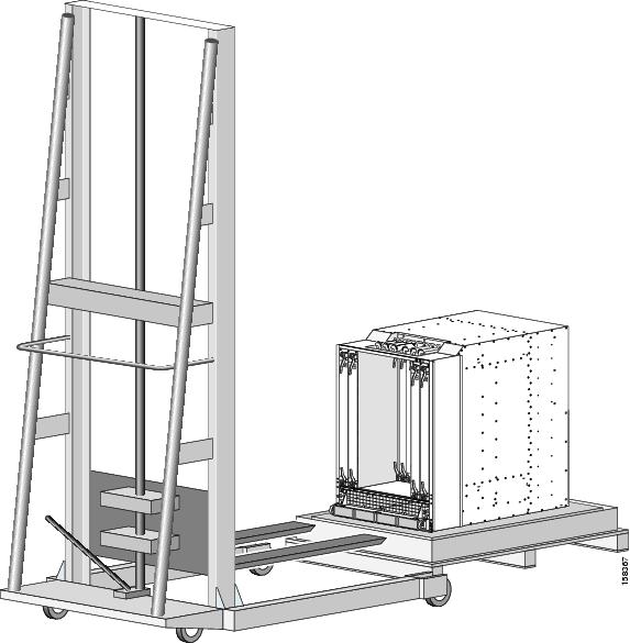 |
||
| Step 3 |
Place a piece of cardboard on the surface of the lift. |
||
| Step 4 |
With two people grasping the chassis, slide the chassis carefully from the pallet on top of the cardboard and onto the lift (see the following figure).
 |
What to do next
You are now ready to secure the chassis in the rack with the front mounting brackets, as described in the next section.
Securing the Chassis in the Rack
This procedure describes how to position the chassis and secure it in the rack. The Cisco CRS 4-slot LCC is shipped with the front vertical mounting brackets installed. The rear vertical mounting brackets and horizontal mounting brackets are shipped in an accessory kit.
Note |
We recommend securing the Cisco CRS 4-slot LCC into a rack with the horizontal mounting rails and the front vertical mounting brackets only—using the rear vertical mounting brackets is optional. For instructions on how to mount the rear brackets, see the Attaching the Rear Vertical Mounting Brackets section. |
Tip |
For the chassis to stay within the boundary of the 4-post rack, we recommend that you use a rack with adjustable mounting rails. The front mounting rails should be recessed inside the rack such that the Cisco CRS 4-slot chassis can extend beyond the rack’s front rails by 8.5 inches. |
To secure the Cisco CRS 4-slot LCC into a rack, follow these steps:
SUMMARY STEPS
- With the chassis safely placed on the lifting device, move the chassis into position in front of the rack.
- Lift the chassis to the height at which you wish to install the chassis in the rack (see the figure below).
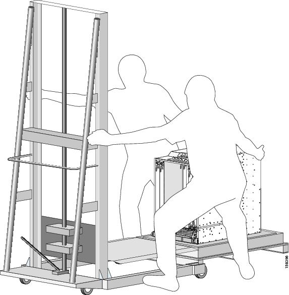
- Use the lift device to align the holes on the chassis vertical mounting bracket with the holes in the rack (see the figure below).
- Use a medium (number 2) Phillips screwdriver and the screws provided in the package to secure the front of the chassis to the rack with the front vertical mounting brackets (see the figure below).
DETAILED STEPS
| Step 1 |
With the chassis safely placed on the lifting device, move the chassis into position in front of the rack. |
||
| Step 2 |
Lift the chassis to the height at which you wish to install the chassis in the rack (see the figure below). 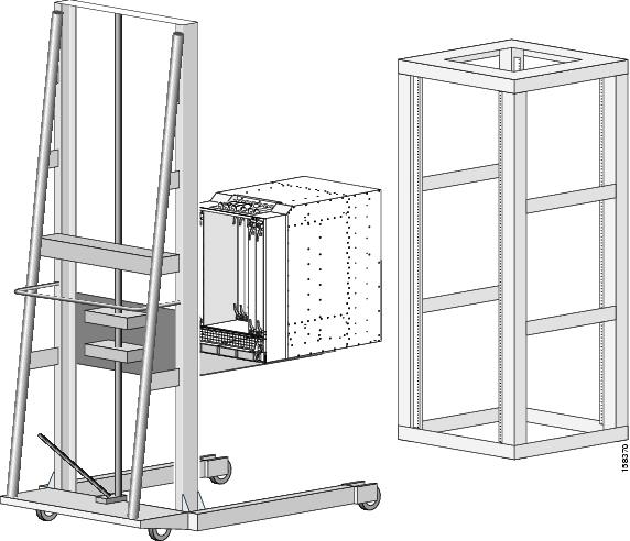
|
||
| Step 3 |
Use the lift device to align the holes on the chassis vertical mounting bracket with the holes in the rack (see the figure below). 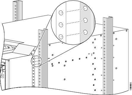 |
||
| Step 4 |
Use a medium (number 2) Phillips screwdriver and the screws provided in the package to secure the front of the chassis to the rack with the front vertical mounting brackets (see the figure below). 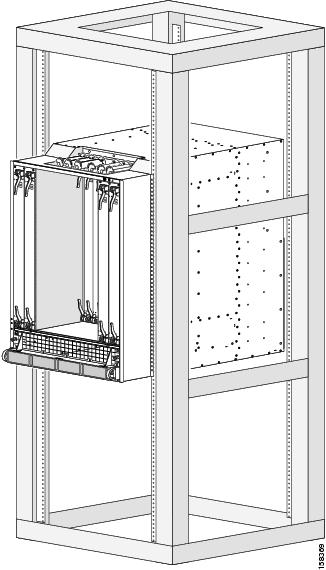 The Cisco CRS 4-slot LCC is now securely mounted in the rack.
|
What to do next
If you choose not to secure the rear of the chassis with the rear mounting brackets, proceed with installing the Cisco CRS 4-slot LCC. For details, see the Cisco CRS Carrier Routing System 4-Slot Line Card Chassis Installation Guide .
For instruction on how to secure the rear of the chassis to the rack as well, go to the next section.
Attaching the Rear Vertical Mounting Brackets
The Cisco CRS 4-slot LCC has been mechanically tested with the front rack mounting brackets only; these tests confirm that the chassis is safely secure in a rack with the front mount only. However, Cisco provides the option to attach the chassis to a rack with the rear vertical mounting brackets as well (in addition to the front mounting brackets).
Tip |
We recommend that you attach the rear vertical mounting brackets to the chassis after the Cisco CRS 4-slot LCC has been mounted in the rack as described in the previous sections of this guide. |
Attaching the rear vertical mounting brackets to the chassis requires these tasks:
- Removing the fan tray
- Removing the rear access panels
- Aligning and attaching the rear mounting brackets
- Reinstalling the rear access panels
- Reinstalling the fan tray
These tasks are described in this section.
Required Tools and Equipment
You need the following tools to perform this task:
- ESD-preventive wrist strap
- Large flat-blade screwdriver
- Medium (number 2) Phillips screwdriver
- 4-mm socket wrench
Removing the Fan Tray
The screws that secure the rear bracket to the chassis wall are screwed in from the inside of the chassis wall. To get access to the screw holes in the upper portion of the mounting bracket, you must remove the fan tray.
SUMMARY STEPS
- To remove the fan tray, attach the ESD-preventive wrist strap to your wrist and connect its leash to one of the ESD connection sockets on the rear side of the chassis or a bare metal surface on the chassis.
- Using a large flat-blade screwdriver, loosen the four captive screws on the fan tray (one on each corner).
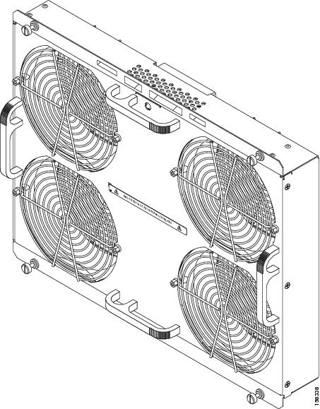
- Grasp the fan tray by the top and bottom handles (see the following figure) and pull it straight out to disconnect the fan tray from the connector mounted on the back of the fan tray.
- Remove the fan tray completely from the fan tray bay.
- Set the fan tray safely aside.
DETAILED STEPS
| Step 1 |
To remove the fan tray, attach the ESD-preventive wrist strap to your wrist and connect its leash to one of the ESD connection sockets on the rear side of the chassis or a bare metal surface on the chassis. |
||
| Step 2 |
Using a large flat-blade screwdriver, loosen the four captive screws on the fan tray (one on each corner).
|
||
| Step 3 |
Grasp the fan tray by the top and bottom handles (see the following figure) and pull it straight out to disconnect the fan tray from the connector mounted on the back of the fan tray.
 |
||
| Step 4 |
Remove the fan tray completely from the fan tray bay. |
||
| Step 5 |
Set the fan tray safely aside.
|
Removing the Rear Access Panels
To secure the lower section of the rear mounting bracket to the chassis, you must access the bay inside the rear access panels.
To remove the rear access panels, follow these steps:
SUMMARY STEPS
- Locate the access panels on the rear of the chassis (see the figure below).
- Using a medium (number 2) Phillips screwdriver, remove the two screws at the top and bottom of one of the access panels and set the screws aside.
- Remove the access panel; then remove the second access panel as described in Step 2, and set aside both access panels and their screws.
DETAILED STEPS
| Step 1 |
Locate the access panels on the rear of the chassis (see the figure below). 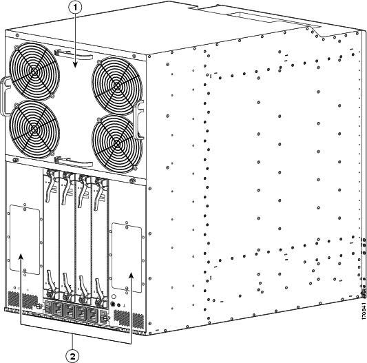
|
||||
| Step 2 |
Using a medium (number 2) Phillips screwdriver, remove the two screws at the top and bottom of one of the access panels and set the screws aside. |
||||
| Step 3 |
Remove the access panel; then remove the second access panel as described in Step 2, and set aside both access panels and their screws. |
Attaching the Rear Mounting Brackets to the Chassis
To attach the rear mounting brackets to the chassis, follow these steps:
SUMMARY STEPS
- If you have not already done so, remove the rear mounting brackets and the bag of 4 mm hex screws from the box they are shipped in.
- Align the top of the rear bracket (on the left or right side of the chassis) to the appropriate screw holes, with the face of the rear bracket facing the face of the front mounting bracket (see Figure 12).
- Initially insert two of the 4-mm hex screws from the inside of the fan tray bay through the chassis wall into the corresponding holes in the rear bracket and screw them in finger tight.
- Move to the lower edge of the rear bracket. From the access panel bay, insert two of the 4-mm hex screws from the inside of the fan tray bay through the chassis wall into the corresponding holes in the rear bracket and screw them in finger tight.
- When the rear bracket is aligned to your satisfaction, use the 4-mm socket wrench to secure the four (two top and two bottom) finger tight screws.
- Insert six more screws in the upper (fan tray) bay and secure them with the 4-mm socket wrench; then do the same with the six screw holes in the lower (access panel) bay.
- Repeat Step 2 through Step 7 for the rear bracket to be attached on the other side of the chassis.
- Using a medium (number 2) Phillips screwdriver, reattach the left and right access panels.
DETAILED STEPS
| Step 1 |
If you have not already done so, remove the rear mounting brackets and the bag of 4 mm hex screws from the box they are shipped in. |
||
| Step 2 |
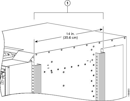
Align the top of the rear bracket (on the left or right side of the chassis) to the appropriate screw holes, with the face of the rear bracket facing the face of the front mounting bracket (see Figure 12).
|
||
| Step 3 |
Initially insert two of the 4-mm hex screws from the inside of the fan tray bay through the chassis wall into the corresponding holes in the rear bracket and screw them in finger tight. |
||
| Step 4 |
Move to the lower edge of the rear bracket. From the access panel bay, insert two of the 4-mm hex screws from the inside of the fan tray bay through the chassis wall into the corresponding holes in the rear bracket and screw them in finger tight. |
||
| Step 5 |
When the rear bracket is aligned to your satisfaction, use the 4-mm socket wrench to secure the four (two top and two bottom) finger tight screws. There are holes for eight 4-mm screws in the upper (fan tray) bay and eight 4-mm screws in the lower (access panel) bays. |
||
| Step 6 |
Insert six more screws in the upper (fan tray) bay and secure them with the 4-mm socket wrench; then do the same with the six screw holes in the lower (access panel) bay. |
||
| Step 7 |
Repeat Step 2 through Step 7 for the rear bracket to be attached on the other side of the chassis. |
||
| Step 8 |
Using a medium (number 2) Phillips screwdriver, reattach the left and right access panels. |
Reinstalling the Fan Tray
To reinstall the fan tray, follow these steps:
SUMMARY STEPS
- Attach the ESD-preventive wrist strap to your wrist and connect its leash to one of the ESD connection sockets on the rear side of the chassis or a bare metal surface on the chassis.
- Holding the fan tray by the top and bottom handles (see Figure 10), position it in front of the fan tray bay.
- Slide the fan tray part-way into its slot.
- Grasp the top and bottom handles of the fan tray and slide it all the way in. Press the fan tray firmly into the chassis so that the connector on the back of the fan tray is seated firmly.
- Using the large flat-blade screwdriver, tighten the four captive screws on the fan tray (one on each corner).
DETAILED STEPS
| Step 1 |
Attach the ESD-preventive wrist strap to your wrist and connect its leash to one of the ESD connection sockets on the rear side of the chassis or a bare metal surface on the chassis. |
||
| Step 2 |
Holding the fan tray by the top and bottom handles (see Figure 10), position it in front of the fan tray bay. |
||
| Step 3 |
Slide the fan tray part-way into its slot. |
||
| Step 4 |
Grasp the top and bottom handles of the fan tray and slide it all the way in. Press the fan tray firmly into the chassis so that the connector on the back of the fan tray is seated firmly.
|
||
| Step 5 |
Using the large flat-blade screwdriver, tighten the four captive screws on the fan tray (one on each corner). |
What to do next
You are now ready to secure the rear mounting brackets to the rack.
Securing the Rear Mounting Brackets to the Rack
To secure the rear mounting brackets to the rack, follow these steps:
SUMMARY STEPS
- Align the holes on the chassis vertical mounting bracket with the holes in the rack (see the figure below).
- Use a medium (number 2) Phillips screwdriver and the screws provided in the package to secure the rear of the chassis to the rack with the left and right rear vertical mounting brackets.
DETAILED STEPS
| Step 1 |
Align the holes on the chassis vertical mounting bracket with the holes in the rack (see the figure below).
 |
||
| Step 2 |
Use a medium (number 2) Phillips screwdriver and the screws provided in the package to secure the rear of the chassis to the rack with the left and right rear vertical mounting brackets. |
What to do next
Proceed with installing the Cisco CRS 4-slot LCC. For details, see the Cisco CRS Carrier Routing System 4-Slot Line Card Chassis Installation Guide .
When You Return Product Components
Before preparing for shipment of the product or product components back to Cisco, you must contact Cisco technical support and provide them with the details of your difficulty. Technical support needs to confirm your product or component failure prior to assigning an RMA number for return shipment. For additional information, see the Obtaining Documentation and Submitting a Service Request section.
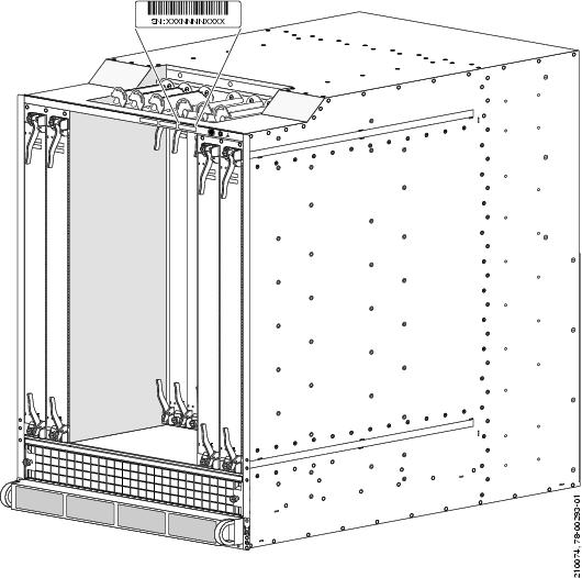
To facilitate your conversation with technical support, locate and note the serial number for your chassis. The serial number label for the Cisco CRS 4-slot LCC is located on the front of the chassis on the chassis edge directly below the cable bracket assembly (see the following figure).
Cisco CRS Documentation Information
This section provides information about the availability of Cisco CRS hardware and software documentation.
Related Documentation
For complete planning, installation, and configuration information for the Cisco CRS 4-slot LCC, refer to the following documents:
Hardware Documents
- Cisco CRS Carrier Routing System 4-Slot Line Card Chassis Site Planning Guide
- Cisco CRS Carrier Routing System 4-Slot Line Card Chassis System Description
- CRS Carrier Routing System 4-Slot Line Card Chassis Installation Guide
- Cisco CRS Carrier Routing System Hardware Documentation Guide
- Cisco CRS Carrier Routing System Ethernet Physical Layer Interface Module (PLIM) Installation Note
- Cisco CRS Carrier Routing System Packet-over-SONET Physical Layer Interface Module (PLIM) Installation Note
- Cisco CRS Fiber-Optic Cleaning Kit Quick Start Guide
- Cisco CRS Carrier Routing System Regulatory Compliance and Safety Information
Software Documents
For a complete listing of available software documentation for the Cisco CRS Carrier Routing System, see About Cisco IOS-XR Software Documentation , available online at the following URL:
http://www.cisco.com/en/US/products/ps5763/products_documentation_roadmaps_list.html
Changes to This Document
The following table lists the technical changes made to this document since it was first printed.
|
Date |
Change Summary |
|---|---|
|
April 2011 |
Added information about new performance route processor (PRP) cards (Cisco product IDs: CRS-8-PRP-6G, CRS-8-PRP-12G). Minor editorial changes were also made. |
|
October 2010 |
Added information about new CRS-MSC-140G and CRS-FP-140 line cards, and CRS-4-FC140/S switch fabric card. Minor editorial changes were also made. |
|
August 2009 |
Updated the document with new chassis shipping information. See the Shipping Carton and Pallet Specifications section, Chassis Packaging Overview section, Removing the Pallet Chassis Support Brackets section, and Transferring the Chassis to a Lifting Device section. |
|
March 2008 |
Minor editorial changes. |
|
August 2007 |
Added the Installing the Horizontal Mounting Rails in the Rack section. |
|
November 2006 |
Initial release of this document. |
Obtaining Documentation and Submitting a Service Request
For information on obtaining documentation, using the Cisco Bug Search Tool (BST), submitting a service request, and gathering additional information, see What's New in Cisco Product Documentation, at: http://www.cisco.com/c/en/us/td/docs/general/whatsnew/whatsnew.html.
Subscribe to What's New in Cisco Product Documentation, which lists all new and revised Cisco technical documentation as an RSS feed and delivers content directly to your desktop using a reader application. The RSS feeds are a free service, and Cisco currently supports RSS Version 2.0.
 Feedback