Cisco CRS Carrier Routing System 16-Slot Line Card Chassis Site Planning Guide
Bias-Free Language
The documentation set for this product strives to use bias-free language. For the purposes of this documentation set, bias-free is defined as language that does not imply discrimination based on age, disability, gender, racial identity, ethnic identity, sexual orientation, socioeconomic status, and intersectionality. Exceptions may be present in the documentation due to language that is hardcoded in the user interfaces of the product software, language used based on RFP documentation, or language that is used by a referenced third-party product. Learn more about how Cisco is using Inclusive Language.
- Updated:
- November 3, 2016
Chapter: Space Planning
Space
Planning
This chapter provides information to help you determine where to install the Cisco CRS Carrier Routing System 16-Slot Line Card Chassis and to plan and prepare the site for the installation of the chassis. It describes the amount of space required for the chassis and provides information about floor loading and drill hole locations for securing the chassis to the floor. This chapter contains the following sections.
Space Planning
This chapter provides information to help you determine where to install the Cisco CRS Carrier Routing System 16-Slot Line Card Chassis and to plan and prepare the site for the installation of the chassis. It describes the amount of space required for the chassis and provides information about floor loading and drill hole locations for securing the chassis to the floor. This chapter contains the following sections:
Basic Cisco CRS Routing System Floor Plans
As part of the site planning process, you must decide where to install the Cisco CRS 16-slot line card chassis. As you consider where to install the system, consider the following:
- Installation site floor plan must
include:
- Enough free space for the chassis (see the Line Card Chassis Footprint).
- Adequate space for airflow and enough room to access chassis components for maintenance (see the Aisle Spacing and Maintenance Access Floor Plan ).
- Additional free space for potential expansion of the system (see the Planning for Future Expansion).
- Floor at the installation site must support the weight of the chassis (see the Chassis Floor Loading).
- Chassis must be bolted to the floor, which means that you must drill holes in the floor for the mounting bolts that secure the chassis to the floor (see the Anchoring the Chassis to the Floor).
- Line Card Chassis Footprint
- Aisle Spacing and Maintenance Access Floor Plan
- Planning for Future Expansion
Line Card Chassis Footprint
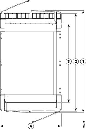
The figure below is a top view of the line card chassis footprint (with optional front and rear cosmetics installed). The front of the chassis is at the top of the figure.
|
1 |
40.236 in. (102.199 cm) |
3 |
32.766 in. (83.226 cm) |
|
2 |
38.264 in. (97.191 cm) |
4 |
23.546 in. (59.807 cm) |
|
1 |
40.236 in. (102.199 cm), depth of LCC with doors attached and closed, |
|
2 |
38.264 in. (97.191 cm), depth of front cable management to rear cable management, excluding doors |
|
3 |
32.766 in. (83.226 cm), distance from front surface to rear surface of the chassis, excluding cable management and doorS |
|
4 |
23.546 in. (59.807 cm), width of chassis |
 Note | A single-shelf (single chassis) system does not require chassis interconnect cabling; therefore, the rear door is optional. |
Aisle Spacing and Maintenance Access Floor Plan
Make sure that enough space exists at the installation site to install the line card chassis and allow sufficient airflow. The floor plan must also provide enough room to access chassis components for maintenance (for example, to remove fan trays, power modules, cables, and air filters). We recommend 48 in. (122 cm) clearance to install the chassis and 36 in. (91.4 cm) clearance to allow for access to chassis components. The below figure shows a typical floor plan.

Cisco provides two layout templates to help you determine where to install the system:
- Aluminum plate template (CRS-LCC-DRILLTEMP) shows the chassis footprint and the pattern of holes that must be drilled into the floor for the mounting brackets that secure the chassis to the floor. See the Anchoring the Chassis to the Floor.
- Mylar template (CRS-LCC-FLOORTEMP) shows the chassis footprint, door swings, and required clearances to remove and replace chassis components. Use this template to plan the aisle space required for the installation and maintenance of a line card chassis.
Note | For front-to-front row alignment and back-to-back row alignment, we recommend that adjacent rows of chassis align the front intake to front intake or rear exhaust to rear exhaust. |
Planning for Future Expansion
When planning the installation of the Cisco CRS-1 routing system, consider potential expansion of the system, such as adding additional line card chassis (single-shelf systems).
When planning for expansion, consider:
- Floor space for additional chassis
- Power and cooling requirements for additional chassis
- Cable management for additional interconnection cables and line card interface cables
- System management for the larger systems
Chassis Floor Loading
Whether you plan to install the chassis on slab concrete or raised floors, ensure that the floor is level and that it can support the weight of the chassis. The table below lists the chassis weight and floor loading for the line card chassis.
|
Chassis Configuration |
Chassis Weight |
Floor Loading |
|---|---|---|
|
Chassis with cards, power components, and front and rear cosmetics (doors, panels, and grilles) |
1753 lb (795 kg) (estimated maximum) |
371 lb per sq ft(0.18 kg per sq cm) |
If you have 3-phase AC Delta or AC Wye at your equipment, a Cisco CRS 3-phase AC power distribution unit (PDU) will be required to convert 3-phase AC input power to single-phase AC input power for the power shelf. The table below lists the weight of two individual PDUs required to be installed for system redundancy, including cables and chassis-mounting brackets.
|
PDU Type |
Weight |
|---|---|
|
CRS-16 Delta PDU (including two PDUs, cables and brackets) |
77 lb (35 kg) |
|
CRS-16 Wye PDU (including two PDUs, cables and brackets) |
51 lb (23 kg) |
For more information about the Cisco CRS 3-Phase AC PDU, refer to the Cisco CRS 3-Phase AC Power Distribution Unit Installation Guide.
Anchoring the Chassis to the Floor
The Cisco CRS chassis must be anchored (bolted) to the floor at the installation site. To assist with this task, an aluminum plate template (CRS-LCC-DRILLTEMP) can be ordered. The template provides drill bushings for the chassis mounting-hole locations.
The template shows the chassis footprint and the pattern of holes that must be drilled into the floor for the mounting brackets that secure the chassis to the floor (see the figure below). The template includes several mounting-hole locations:
- Primary—Use these mounting-hole locations whenever possible.
- Secondary—Use these locations if it is not possible to use the Primary locations.
- Aux—Use these locations when there is an obstruction at both the primary and secondary locations (for example, rebar in a concrete floor or a structure beneath a raised floor). For this situation, Cisco provides an outrigger kit (CRS-16-LCC-ALTMNT) that attaches to the chassis to anchor the chassis to the floor. See the Cisco CRS Carrier Routing System 16-Slot Line Card Chassis Unpacking, Moving, and Securing Guide for instructions on installing the outrigger kit.
Slab Concrete Floors
Cisco has contracted with Hilti Corporation to provide a kit for installation of the Cisco CRS chassis on concrete floors. The kit contains instructions, fasteners, and washers. In addition, a nonstandard 18-mm concrete drill is required to install the studs. This drill can be ordered from Hilti.
Raised Floors
If you plan to install the line card chassis on a raised floor or you need to reinforce the floor to support the weight of the chassis, be sure to follow the instructions from the raised-floor manufacturer.
The figure below shows the drill hole template with the mounting hole locations, which are marked in each of the four corners of the template.

|
1 |
Primary LCC/FCC mount location (preferred) |
3 |
Secondary LCC/FCC mount location |
|
2 |
Aux LCC mount location (requires CRS-16-LCC-ALTMNT kit) |
4 |
Aux FCC mount location (requires CRS-16-FCC-ALTMNT kit) |
 Feedback