- Title and copyright: PA-4R-DTR Dedicated Token Ring Port Adapter Installation and Configuration
- Preface: PA-4R-DTR Dedicated Token Ring Port Adapter Installation and Configuration
- Overview: PA-4R-DTR Dedicated Token Ring Port Adapter Installation and Configuration
- Preparing to Install the PA-4R-DTR Dedicated Token Ring Port Adapter
- Removing and Installing the PA-4R-DTR Dedicated Token Ring Port Adapter
- Configuring the PA-4R-DTR Dedicated Token Ring Port Adapter
PA-4R-DTR Dedicated Token Ring Port Adapter Installation and Configuration
Bias-Free Language
The documentation set for this product strives to use bias-free language. For the purposes of this documentation set, bias-free is defined as language that does not imply discrimination based on age, disability, gender, racial identity, ethnic identity, sexual orientation, socioeconomic status, and intersectionality. Exceptions may be present in the documentation due to language that is hardcoded in the user interfaces of the product software, language used based on RFP documentation, or language that is used by a referenced third-party product. Learn more about how Cisco is using Inclusive Language.
- Updated:
- September 14, 2007
Chapter: Overview: PA-4R-DTR Dedicated Token Ring Port Adapter Installation and Configuration
Overview
This chapter describes the PA-4R-DTR and contains the following sections:
•![]() LEDs
LEDs
•![]() Cables, Connectors, and Pinouts
Cables, Connectors, and Pinouts
•![]() Port Adapter Slot Locations on the Supported Platforms
Port Adapter Slot Locations on the Supported Platforms
•![]() Identifying Interface Addresses
Identifying Interface Addresses
Port Adapter Overview
The PA-4R-DTR, shown in Figure 1-4 provides up to four IBM Token Ring or IEEE 802.5 Token Ring interfaces. You can set each Token Ring interface for 4-Mbps or 16-Mbps, half-duplex or full-duplex operation, and each interface can operate as a concentrator port or a classic Token Ring station. All Token Ring ports run at wire speed.

Note ![]() Port adapters have a handle, but this handle is not always shown in figures in this publication to allow a full view of the detail on the port adapter faceplate.
Port adapters have a handle, but this handle is not always shown in figures in this publication to allow a full view of the detail on the port adapter faceplate.
Figure 1-1 PA-4R-DTR—Faceplate View

Note ![]() While the VIP2 supports online insertion and removal (OIR), individual port adapters do not. To replace port adapters in Cisco 7000 series and Cisco 7500 series routers, you must first remove the VIP2 from the chassis and then replace port adapters as required. Cisco 7200 series routers support OIR of port adapters.
While the VIP2 supports online insertion and removal (OIR), individual port adapters do not. To replace port adapters in Cisco 7000 series and Cisco 7500 series routers, you must first remove the VIP2 from the chassis and then replace port adapters as required. Cisco 7200 series routers support OIR of port adapters.
Token Ring Overview
The following sections describe Token Ring specifications, physical connections, connection equipment, and cables and connectors:
•![]() Token Ring Connection Equipment
Token Ring Connection Equipment
•![]() Token Ring Distance Limitations
Token Ring Distance Limitations
•![]() Token Ring Speed Considerations
Token Ring Speed Considerations
Token Ring Specifications
Token Ring refers to both the IBM Token Ring network and the IEEE 802.5 networks. The IEEE 802.5 specification was modeled after, and still closely shadows, the IBM network. The two networks are compatible, but their specifications differ slightly.
Token Ring and IEEE 802.5 are token-passing networks that move a small frame (called a token) around the network. Possession of the token grants the right to transmit; a station with information to transmit must wait until a free token passes.
The IBM Token Ring network specifies a star topology, with all end stations connected through a device called a multistation access unit (MSAU) for half-duplex functionality or through a Token Ring switch for full-duplex functionality. IEEE 802.5 does not specify any topology, although most implementations are based on a star configuration with end stations attached to a device called a media access unit (MAU) for half-duplex functionality or to a Token Ring switch for full-duplex functionality. IBM Token Ring specifies twisted-pair cabling, but IEEE 802.5 does not specify a media type. Most Token Ring networks use foil twisted-pair (FTP) cabling; however, networks that operate at 4 Mbps sometimes use unshielded twisted-pair cable (UTP). shows a comparison of the two networks.
All PA-4R-DTR interfaces support both 4- and 16-Mbps, half-duplex and full-duplex operation, concentrator port and station port operation, and early token release. You can change the configuration using the following commands issued in configuration mode:
•![]() To enable 16-Mbps operation, specify the slot/port address and use the ring-speed 16 command. To enable 4-Mbps operation, specify the slot/port address and use the ring-speed 4 command.
To enable 16-Mbps operation, specify the slot/port address and use the ring-speed 16 command. To enable 4-Mbps operation, specify the slot/port address and use the ring-speed 4 command.
•![]() To enable early token release, specify the slot/port address and use the early token release command. To disable early token release, specify the slot/port address and use the no early token release command.
To enable early token release, specify the slot/port address and use the early token release command. To disable early token release, specify the slot/port address and use the no early token release command.
•![]() To enable full-duplex operation, specify the slot/port address and use the full-duplex command. To return to half-duplex operation, specify the slot/port address and use the no full-duplex command or half-duplex command.
To enable full-duplex operation, specify the slot/port address and use the full-duplex command. To return to half-duplex operation, specify the slot/port address and use the no full-duplex command or half-duplex command.
•![]() To enable DTR concentrator port mode on the interface, specify the slot/port address and use the port command. When enabled, the interface operates in concentrator port mode. To disable DTR concentrator port mode on the interface, specify the slot/port address and use the no port command. When disabled, the interface operates in station mode.
To enable DTR concentrator port mode on the interface, specify the slot/port address and use the port command. When enabled, the interface operates in concentrator port mode. To disable DTR concentrator port mode on the interface, specify the slot/port address and use the no port command. When disabled, the interface operates in station mode.
For complete descriptions and examples of software commands, refer to the related software configuration documentation.
Token Ring Port Operation
The Token Ring ports operate in the following modes:
•![]() Half-duplex concentrator port—The port is connected to a single station in half-duplex mode. The port behaves like an active MAU port for classical Token Ring.
Half-duplex concentrator port—The port is connected to a single station in half-duplex mode. The port behaves like an active MAU port for classical Token Ring.
•![]() Half-duplex station emulation—The port is connected to a port on an MAU. The port behaves like a station connected to a classical Token Ring segment that contains multiple stations.
Half-duplex station emulation—The port is connected to a port on an MAU. The port behaves like a station connected to a classical Token Ring segment that contains multiple stations.
•![]() Full-duplex concentrator port—The port is connected to a single station in full-duplex mode.
Full-duplex concentrator port—The port is connected to a single station in full-duplex mode.
•![]() Full-duplex station emulation—The port is connected to a switch or a concentrator port in full-duplex mode.
Full-duplex station emulation—The port is connected to a switch or a concentrator port in full-duplex mode.
In a typical half-duplex Token Ring network, lobe cables connect each Token Ring station (PA-4R-DTR interface) to the MAU and patch cables connect adjacent MAUs to form one large ring. (See Figure 1-2.)
Figure 1-2 Half-Duplex Token Ring Network Physical Connections

In a typical full-duplex Token Ring network, lobe cables connect each Token Ring station (PA-4R-DTR interface) to the Token Ring switch and patch cables connect adjacent Token Ring switches to form one large ring. (See Figure 1-3.)
Figure 1-3 Full-Duplex Token Ring Network Physical Connections

Dedicated Token Ring
Classic 4- and 16-Mbps Token Ring adapters are connected to a port on a concentrator. These adapters are also limited to operating in half-duplex mode. In half-duplex mode, the adapter only sends or receives a frame; it cannot do both simultaneously.
DTR, developed by the IEEE, defines a method in which the port emulates a concentrator port and eliminates the need for an intermediate concentrator. DTR defines a full-duplex data-passing mode called transmit immediate. Transmit immediate eliminates the need for a token and allows the adapter to simultaneously transmit and receive.
DTR is particularly useful for providing improved access to servers because a server is attached directly to a router. This direct attachment allows the server to take advantage of the full 16-Mbps bandwidth available for sending and receiving data and results in an aggregate bandwidth of 32 Mbps.
Token Ring Connection Equipment
You need an IEEE 802.5 MAU, MSAU, or a Token Ring switch to provide the interface between the PA-4R-DTR Token Ring interfaces and the external ring. You also need a Token Ring lobe cable between each PA-4R-DTR interface and the MAU, MSAU, or the Token Ring switch.
Note ![]() Lobe cables connect each Token Ring station (PA-4R-DTR interface) to the MAU, MSAU, or Token Ring switch. Patch cables can connect adjacent MSAUs or Token Ring switches to form one large ring.
Lobe cables connect each Token Ring station (PA-4R-DTR interface) to the MAU, MSAU, or Token Ring switch. Patch cables can connect adjacent MSAUs or Token Ring switches to form one large ring.
PA-4R-DTR interfaces operate at 4 or 16 Mbps. You can set the port speed using the ring-speed n configuration command, where n is the speed (4 or 16) in megabits per second. The speed of each Token Ring port must match the speed of the ring to which it is connected. Before you enable the Token Ring interfaces, ensure that each interface is set for the correct speed, or you risk bringing down the ring.

Token Ring Distance Limitations
The maximum transmission distance is not defined for IEEE 802.5 networks. FTP cabling is most commonly used for 4- and 16-Mbps ring-speed rates. Because twisted-pair cabling is more susceptible to interference than other types of cabling, the network length and repeater spacing must be planned accordingly.
Token Ring Speed Considerations
Before you install the PA-4R-DTR, determine the ring speed of each ring that you plan to connect to the server. There is no factory default for the interface speed. You must set the speed of each interface (within the setup command facility or using the ring-speed command) before you bring up the interface and insert it into the ring using the no shutdown command.
LEDs
The PA-4R-DTR has four status LEDs for each port and one enabled LED. (See Figure 1-4.) The green- and amber-colored LED for each port indicates port status.
Figure 1-4 LEDs on the PA-4R-DTR—Horizontal Orientation
After system initialization, the enabled LED goes on to indicate that the port adapter has been enabled for operation.
The following conditions must be met before the PA-4R-DTR is enabled:
•![]() The port adapter is correctly connected to the backplane or midplane and receiving power.
The port adapter is correctly connected to the backplane or midplane and receiving power.
•![]() A valid system software image for the port adapter is downloaded.
A valid system software image for the port adapter is downloaded.
•![]() The system recognizes the port adapter or PA-4R-DTR-equipped VIP2.
The system recognizes the port adapter or PA-4R-DTR-equipped VIP2.
If these conditions are met and the initialization occurs, the enabled LED goes on.
If any of the above conditions are not met, or if the initialization fails for other reasons, the enabled LED does not go on.
Table 1-2 lists LED colors and indications.
Cables, Connectors, and Pinouts
A network interface cable provides the connection between the RJ-45 Token Ring receptacles on the PA-4R-DTR and an MAU or Token Ring switch. The RJ-45 connector at the PA-4R-DTR end and the MAU or Token Ring switch connector at the network end are described in the "Token Ring Connection Equipment" section.
The Token Ring ports on the PA-4R-DTR are RJ-45 receptacles that require Type 1 or Type 3 lobe cables. Token Ring interface cables are not available from Cisco, but are commercially available through outside cable vendors.
Type 1 lobe cables use FTP cable and terminate at the network end with a large MAU plug. (see Figure 1-5.) The PA-4R-DTR end of the cable is an RJ-45 connector. Table 1-2 lists the pinouts and signals for the PA-4R-DTR.
Figure 1-5 Token Ring Type 1 Lobe Cable Connectors—RJ-45 and MAU Types

Type 3 lobe cables use either FTP or UTP cable and terminate at the network end with an RJ-11 plug. (See Figure 1-6.) The PA-4R-DTR end of the cable is an RJ-45 connector.
Figure 1-6 Token Ring Type 3 Lobe Cable Connectors—RJ-45 and RJ-11 Types


Warning ![]() The ports labeled "Ethernet", "10BaseT", "Token Ring", "Console", and "AUX" are safety extra-low voltage (SELV) circuits. SELV circuits should only be connected to other SELV circuits. Because the Basic Rate Interface (BRI) circuits are treated like telephone-network voltage avoid connecting the SELV circuit to the telephone network voltage circuits.
The ports labeled "Ethernet", "10BaseT", "Token Ring", "Console", and "AUX" are safety extra-low voltage (SELV) circuits. SELV circuits should only be connected to other SELV circuits. Because the Basic Rate Interface (BRI) circuits are treated like telephone-network voltage avoid connecting the SELV circuit to the telephone network voltage circuits.
|
|
|
|---|---|
1 |
Receive Data + (RxD+) |
2 |
RxD- |
3 |
Transmit Data + (TxD+) |
6 |
TxD- |
Note ![]() Proper common-mode line terminations should be used for the unused Category 5 UTP cable pairs 4/5 and 7/8. Common-mode termination reduces the contributions to electromagnetic interference (EMI) and susceptibility to common-mode sources.
Proper common-mode line terminations should be used for the unused Category 5 UTP cable pairs 4/5 and 7/8. Common-mode termination reduces the contributions to electromagnetic interference (EMI) and susceptibility to common-mode sources.
Depending on your RJ-45 interface cabling requirements, use the pinouts in Figure 1-7 and Figure 1-8.
Figure 1-7 Straight-Through Cable Pinout—PA-4R-DTR RJ-45 Connection to a Hub or Repeater

Figure 1-8 Crossover Cable Pinout—PA-4R-DTR RJ-45 Connections Between Hubs and Repeaters

Port Adapter Slot Locations on the Supported Platforms
This section discusses port adapter slot locations on the supported platforms. The illustrations that follow summarize slot location conventions on each platform.
Cisco 7100 Series Routers Slot Numbering
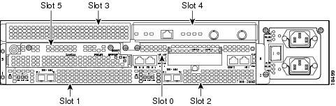
The PA-4R-DTR can be installed in port adapter slot 3 in Cisco 7120 series routers, and in port adapter slot 4 in Cisco 7140 series routers. Figure 1-9 shows a Cisco 7120 with a port adapter installed in slot 3. Figure 1-10 shows a Cisco 7140 with a port adapter installed in slot 4.
Figure 1-9 Port Adapter Slots in the Cisco 7100 Series Router—Cisco 7120 Series
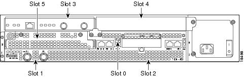
Figure 1-10 Port Adapter Slots in the Cisco 7100 Series Router—Cisco 7140 Series
Cisco 7200 Series Routers Slot Numbering
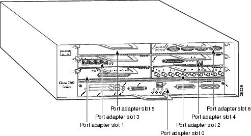
Figure 1-11 shows a Cisco 7206 with port adapters installed. In the Cisco 7206 (including the Cisco 7206 and Cisco 7206VXR as router shelves in a Cisco AS5800 Universal Access Server), port adapter slot 1 is in the lower left position, and port adapter slot 6 is in the upper right position. (The Cisco 7202 and Cisco 7204 are not shown; however, the PA-4R-DTR can be installed in any available port adapter slot.)
Figure 1-11 Port Adapter Slots in the Cisco 7206
VIP2 Slot Numbering
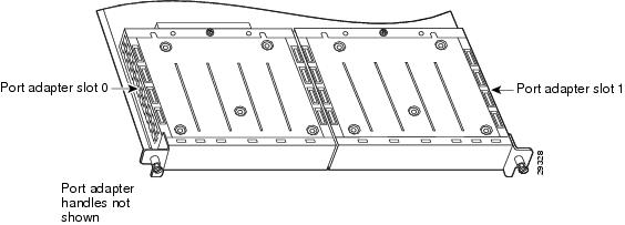
Figure 1-12 shows a partial view of a VIP motherboard with installed port adapters. With the motherboard oriented as shown in Figure 1-12, the left port adapter is in port adapter slot 0, and the right port adapter is in port adapter slot 1. The slot numbering is the same for the Catalyst RSM/VIP2. The slots are always numbered 0 and 1.
Figure 1-12 VIP Motherboard with Two Port Adapters Installed—Horizontal Orientation
Note ![]() In the Cisco 7000, Cisco 7507, and Cisco 7513 chassis, the VIP motherboard is installed vertically. In the Cisco 7010 and Cisco 7505 chassis, the VIP motherboard is installed horizontally.
In the Cisco 7000, Cisco 7507, and Cisco 7513 chassis, the VIP motherboard is installed vertically. In the Cisco 7010 and Cisco 7505 chassis, the VIP motherboard is installed horizontally.
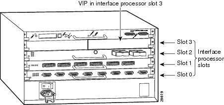
Interface processor slots are numbered as shown in Figure 1-13.
Figure 1-13 Interface Slot Numbers—Cisco 7505 Shown
Identifying Interface Addresses
This section describes how to identify interface addresses for the PA-4R-DTR in supported platforms. Interface addresses specify the actual physical location of each interface on a router or switch.
Interfaces on the PA-4R-DTR installed in a router maintain the same address regardless of whether other port adapters are installed or removed. However, when you move a port adapter to a different slot, the first number in the interface address changes to reflect the new port adapter slot number.
Interfaces on a PA-4R-DTR installed in a VIP2 maintain the same address regardless of whether other interface processors are installed or removed. However, when you move a VIP2 to a different slot, the interface processor slot number changes to reflect the new interface processor slot.
Note ![]() Interface ports are numbered from left to right starting with 0.
Interface ports are numbered from left to right starting with 0.
Table 1-4 explains how to identify interface addresses.
|
|
|
|
|
|---|---|---|---|
Cisco 7120 series routers |
Port-adapter-slot-number/interface-port-number |
Port adapter slot—always 3 Interface port—0 through 3 |
3/1 |
Cisco 7140 series routers |
Port-adapter-slot-number/interface-port-number |
Port adapter slot—always 4 Interface port—0 through 3 |
4/0 |
Cisco 7200 series routers |
Port-adapter-slot-number/interface-port-number |
Port adapter slot—0 through 6 (depends on the number of slots in the router)1 Interface port—0 through 3 |
1/0 |
VIP2 in Cisco 7000 series or |
Interface-processor-slot-number/port-adapter-slot- |
Interface processor slot—0 through 12 (depends on the number of slots in the router) Port adapter slot—always 0 or 1 Interface port—0 through 3 |
3/1/0 |
1 Port adapter slot 0 is reserved for the Fast Ethernet port on the I/O controller (if present). |
Cisco 7100 Series Routers Interface Addresses
This section describes how to identify the interface addresses used for the PA-4R-DTR in Cisco 7100 series routers. The interface address is composed of a two-part number in the format port-adapter-slot-number/interface-port-number. See Table 1-4 for the interface address format.
Cisco 7200 Series Routers Interface Addresses
This section describes how to identify the interface addresses used for the PA-4R-DTR in Cisco 7200 series routers. The interface address is composed of a two-part number in the format port-adapter-slot-number/interface-port-number. See Table 1-4 for the interface address format.
In Cisco 7200 series routers, port adapter slots are numbered from the lower left to the upper right, beginning with port adapter slot 1 and continuing through port adapter slot 2 for the Cisco 7202, slot 4 for the Cisco 7204 and Cisco 7204VXR, and slot 6 for the Cisco 7206 and Cisco 7206VXR. (Port adapter slot 0 is reserved for the optional Fast Ethernet port on the I/O controller—if present.)
The interface addresses of the interfaces on the PA-4R-DTR in port adapter slot 1 are
1/0 through 1/3 (port adapter slot 1 and interfaces 0 through 3). If the PA-4R-DTR was in port adapter slot 4, these same interfaces would be numbered 4/0 through 4/3 (port adapter slot 4 and interfaces
0 through 7).
VIP2 Interface Addresses
This section describes how to identify the interface addresses used for the PA-4R-DTR on a VIP2 in Cisco 7000 series and Cisco 7500 series routers.
Note ![]() Although the processor slots in the 7-slot Cisco 7000 and Cisco 7507 and the 13-slot Cisco 7513 and Cisco 7576 are vertically oriented and those in the 5-slot Cisco 7010 and Cisco 7505 are horizontally oriented, all Cisco 7000 series and Cisco 7500 series routers use the same method for slot and port numbering.
Although the processor slots in the 7-slot Cisco 7000 and Cisco 7507 and the 13-slot Cisco 7513 and Cisco 7576 are vertically oriented and those in the 5-slot Cisco 7010 and Cisco 7505 are horizontally oriented, all Cisco 7000 series and Cisco 7500 series routers use the same method for slot and port numbering.
See Table 1-4 for the interface address format. The interface address is composed of a three-part number in the format interface-processor-slot-number/port-adapter-slot-number/interface-port-number.
If the VIP2 is inserted in interface processor slot 3, then the interface addresses of the PA-4R-DTR are 3/1/0 through 3/1/7 (interface processor slot 3, port adapter slot 1, and interfaces 0 through 7). If the port adapter was in port adapter slot 0 on the VIP2, these same interface addresses would be numbered 3/0/0 through 3/0/7.
Note ![]() If you remove the VIP2 with the PA-4R-DTR (shown in Figure 1-13) from interface processor slot 3 and install it in interface processor slot 2, the interface addresses become 2/1/0 through 2/1/7.
If you remove the VIP2 with the PA-4R-DTR (shown in Figure 1-13) from interface processor slot 3 and install it in interface processor slot 2, the interface addresses become 2/1/0 through 2/1/7.
 Feedback