- Title and copyright: PA-A1 ATM Port Adapter Installation and Configuration
- Preface: PA-A1 ATM Port Adapter Installation and Configuration
- Overview: PA-A1 ATM Port Adapter
- Preparing to Install the PA-A1 ATM Port Adapter
- Removing and Installing the PA-A1 ATM Port Adapter
- Attaching the PA-A1 ATM Interface Cables
- Configuring the PA-A1 ATM Port Adapter
PA-A1 ATM Port Adapter Installation and Configuration
Bias-Free Language
The documentation set for this product strives to use bias-free language. For the purposes of this documentation set, bias-free is defined as language that does not imply discrimination based on age, disability, gender, racial identity, ethnic identity, sexual orientation, socioeconomic status, and intersectionality. Exceptions may be present in the documentation due to language that is hardcoded in the user interfaces of the product software, language used based on RFP documentation, or language that is used by a referenced third-party product. Learn more about how Cisco is using Inclusive Language.
- Updated:
- September 14, 2007
Chapter: Configuring the PA-A1 ATM Port Adapter
Configuring the PA-A1 ATM
To continue your PA-A1 ATM port adapter installation, you must configure the ATM interfaces. The instructions that follow apply to all supported platforms. Minor differences among the platforms—with Cisco IOS software commands—are noted.
This chapter contains the following sections:
•![]() Using the EXEC Command Interpreter
Using the EXEC Command Interpreter
Using the EXEC Command Interpreter
You modify the configuration of your router through the software command interpreter called the EXEC (also called enable mode). You must enter the privileged level of the EXEC command interpreter with the enable command before you can use the configure command to configure a new interface or change the existing configuration of an interface. The system prompts you for a password if one has been set.
The system prompt for the privileged level ends with a pound sign (#) instead of an angle bracket (>). At the console terminal, use the following procedure to enter the privileged level:
Step 1 ![]() At the user-level EXEC prompt, enter the enable command. The EXEC prompts you for a privileged-level password as follows:
At the user-level EXEC prompt, enter the enable command. The EXEC prompts you for a privileged-level password as follows:
Router> enable
Password:
Step 2 ![]() Enter the password (the password is case sensitive). For security purposes, the password is not displayed.
Enter the password (the password is case sensitive). For security purposes, the password is not displayed.
When you enter the correct password, the system displays the privileged-level system prompt (#):
Router#
To configure the new interfaces, proceed to the "Configuring the Interfaces" section.
Configuring the Interfaces
After you verify that the new PA-A1 ATM is installed correctly (the enabled LED goes on), use the privileged-level configure command to configure the new interfaces. Have the following information available:
•![]() Protocols you plan to route on each new interface
Protocols you plan to route on each new interface
•![]() IP addresses, if you plan to configure the interfaces for IP routing
IP addresses, if you plan to configure the interfaces for IP routing
•![]() Bridging protocols you plan to use
Bridging protocols you plan to use
•![]() Whether the new interfaces will use LAN Emulation (LANE)
Whether the new interfaces will use LAN Emulation (LANE)
If you installed a new PA-A1 ATM or if you want to change the configuration of an existing interface, you must enter configuration mode to configure the new interfaces. If you replaced a PA-A1-ATM that was previously configured, the system will recognize the new interfaces and brings each of them up in their existing configuration.
For a summary of the configuration commands available and instructions for configuring interfaces on a PA-A1 ATM, refer to the appropriate configuration publications listed in the "Related Documentation" section.
You execute configuration commands from the privileged level of the EXEC command interpreter, which usually requires password access. Contact your system administrator, if necessary, to obtain password access. (See the "Using the EXEC Command Interpreter" section for an explanation of the privileged level of the EXEC.)
This section contains the following subsections:
•![]() Performing a Basic Configuration
Performing a Basic Configuration
Shutting Down an Interface
Before you remove an interface that you will not replace, replace an ATM interface cable, or replace port adapters, use the shutdown command to shut down (disable) the interfaces to prevent anomalies when you reinstall the new or reconfigured interface processor. When you shut down an interface, it is designated administratively down in the show command displays.
Follow these steps to shut down an interface:
Step 1 ![]() Enter the privileged level of the EXEC command interpreter (also called enable mode). (See the "Using the EXEC Command Interpreter" section for instructions.)
Enter the privileged level of the EXEC command interpreter (also called enable mode). (See the "Using the EXEC Command Interpreter" section for instructions.)
Step 2 ![]() At the privileged-level prompt, enter configuration mode and specify that the console terminal will be the source of the configuration subcommands, as follows:
At the privileged-level prompt, enter configuration mode and specify that the console terminal will be the source of the configuration subcommands, as follows:
Router# configure terminal
Enter configuration commands, one per line. End with CNTL/Z.
Router(config)#
Step 3 ![]() Shut down interfaces by entering the interface atm subcommand (followed by the interface address of the interface), and then enter the shutdown command. Table 5-1 shows the command syntax.
Shut down interfaces by entering the interface atm subcommand (followed by the interface address of the interface), and then enter the shutdown command. Table 5-1 shows the command syntax.
When you have finished, press Ctrl-Z—hold down the Control key while you press Z—or enter end or exit to exit configuration mode and return to the EXEC command interpreter.

Note ![]() For the Cisco 7206 and Cisco 7206VXR router shelves, the interface specified in the above example would include a shelf number. For example, the command interface atm 5/2/0 would specify the first ATM interface of the port adapter in slot 2 of Cisco 7206 or 7206VXR router shelf 5. See Table 5-1.
For the Cisco 7206 and Cisco 7206VXR router shelves, the interface specified in the above example would include a shelf number. For example, the command interface atm 5/2/0 would specify the first ATM interface of the port adapter in slot 2 of Cisco 7206 or 7206VXR router shelf 5. See Table 5-1.
Note ![]() If you need to shut down additional interfaces, enter the interface atm command (followed by the interface address of the interface) for each of the interfaces on your port adapter. Use the no shutdown command to enable the interface.
If you need to shut down additional interfaces, enter the interface atm command (followed by the interface address of the interface) for each of the interfaces on your port adapter. Use the no shutdown command to enable the interface.
Step 4 ![]() Write the new configuration to NVRAM as follows:
Write the new configuration to NVRAM as follows:
Router# copy running-config startup-config
[OK]
Router#
The system displays an OK message when the configuration has been stored in NVRAM.
Step 5 ![]() Verify that new interfaces are now in the correct state (shut down) using the show interfaces command (followed by the interface type and interface address of the interface) to display the specific interface. Table 5-2 provides examples.
Verify that new interfaces are now in the correct state (shut down) using the show interfaces command (followed by the interface type and interface address of the interface) to display the specific interface. Table 5-2 provides examples.
Note ![]() For the Cisco 7206 and Cisco 7206VXR as router shelves, the show interfaces command requires a shelf number in the format show interfaces atm shelf-number/port-adapter-slot/interface.
For the Cisco 7206 and Cisco 7206VXR as router shelves, the show interfaces command requires a shelf number in the format show interfaces atm shelf-number/port-adapter-slot/interface.
Step 6 ![]() Reenable the interfaces by doing the following:
Reenable the interfaces by doing the following:
a. ![]() Repeat Step 3 to reenable an interface. Substitute the no shutdown command for the shutdown command.
Repeat Step 3 to reenable an interface. Substitute the no shutdown command for the shutdown command.
b. ![]() Repeat Step 4 to write the new configuration to memory. Use the copy running-config startup-config command.
Repeat Step 4 to write the new configuration to memory. Use the copy running-config startup-config command.
c. ![]() Repeat Step 5 to verify that the interfaces are in the correct state. Use the show interfaces command followed by the interface type and interface address of the interface.
Repeat Step 5 to verify that the interfaces are in the correct state. Use the show interfaces command followed by the interface type and interface address of the interface.
For complete descriptions of software configuration commands, refer to the publications listed in the "Related Documentation" section.
Performing a Basic Configuration
Following are instructions for a basic configuration: enabling an interface, specifying IP routing, setting the MTU size, and configuring SONET framing. You might also need to enter other configuration subcommands, depending on the requirements for your system configuration and the protocols you plan to route on the interface. For complete descriptions of configuration subcommands and the configuration options available for ATM interfaces, refer to the appropriate software documentation.
In the following procedure, press the Return key after each step unless otherwise noted. At any time you can exit the privileged level and return to the user level by entering disable at the prompt as follows:
Router# disable
Router>
Step 1 ![]() Enter configuration mode and specify that the console terminal is the source of the configuration subcommands, as follows:
Enter configuration mode and specify that the console terminal is the source of the configuration subcommands, as follows:
Router# configure terminal
Enter configuration commands, one per line. End with CNTL/Z.
Router(config)#
Step 2 ![]() Specify the first interface to configure by entering the interface atm subcommand, followed by the interface address of the interface you plan to configure. Table 5-3 provides examples.
Specify the first interface to configure by entering the interface atm subcommand, followed by the interface address of the interface you plan to configure. Table 5-3 provides examples.
Step 3 ![]() Assign an IP address and subnet mask to the interface (if IP routing is enabled on the system), by using the ip address subcommand, as in the following example:
Assign an IP address and subnet mask to the interface (if IP routing is enabled on the system), by using the ip address subcommand, as in the following example:
Router(config-if)# ip address 10.0.0.0 10.255.255.255
Step 4 ![]() Add any additional configuration subcommands required to enable routing protocols and set the interface characteristics. Table 5-4 provides examples of other ATM subcommands.
Add any additional configuration subcommands required to enable routing protocols and set the interface characteristics. Table 5-4 provides examples of other ATM subcommands.
Step 5 ![]() Reenable the interfaces using the no shutdown command. (See the "Shutting Down an Interface" section.)
Reenable the interfaces using the no shutdown command. (See the "Shutting Down an Interface" section.)
Step 6 ![]() Configure all additional port adapter interfaces as required.
Configure all additional port adapter interfaces as required.
Step 7 ![]() After including all of the configuration subcommands to complete your configuration, press Ctrl-Z—hold down the Control key while you press Z—or enter end or exit to exit configuration mode and return to the EXEC command interpreter prompt.
After including all of the configuration subcommands to complete your configuration, press Ctrl-Z—hold down the Control key while you press Z—or enter end or exit to exit configuration mode and return to the EXEC command interpreter prompt.
Step 8 ![]() Write the new configuration to NVRAM as follows:
Write the new configuration to NVRAM as follows:
Router# copy running-config startup-config
[OK]
Router#
This completes the procedure for creating a basic configuration.
Virtual Circuits
A virtual circuit (VC) is a point-to-point connection between remote hosts and routers. A VC is established for each ATM end node with which the router communicates. The characteristics of the VC are established when the VC is created and include the following:
•![]() Quality of service (QoS)
Quality of service (QoS)
•![]() ATM adaptation layer 5 (AAL5) mode
ATM adaptation layer 5 (AAL5) mode
•![]() Encapsulation type (Logical Link Control/Subnetwork Access Protocol (, multiplexing device, and Q.2931 Signaling ATM Adaption Layer)
Encapsulation type (Logical Link Control/Subnetwork Access Protocol (, multiplexing device, and Q.2931 Signaling ATM Adaption Layer)
Each VC supports the following router functions:
•![]() Multiprotocol (AppleTalk, CLNS, DECnet, IP, IPX, VINES, XNS)
Multiprotocol (AppleTalk, CLNS, DECnet, IP, IPX, VINES, XNS)
•![]() Fast switching of IP packets
Fast switching of IP packets
•![]() Pseudobroadcast support for multicast packets
Pseudobroadcast support for multicast packets
By default, fast switching is enabled on all PA-A1 ATM interfaces. These switching features can be turned off with interface configuration commands. Autonomous switching must be explicitly enabled per interface.
Configuring Permanent Virtual Circuits
All permanent virtual circuits (PVCs) configured into the router remain active until the circuit is removed from the configuration. The PVCs also require a permanent connection to the ATM switch. All virtual circuit characteristics apply to PVCs. When a PVC is configured, all the configuration options are passed on to the PA-A1 ATM. These PVCs can be written into the nonvolatile RAM (NVRAM) as part of the Route Processor (RP) configuration and are used when the RP image is reloaded.
Some ATM switches have point-to-multipoint PVCs that do the equivalent of broadcasting. If a point-to-multipoint PVC exists, then that PVC can be used as the sole broadcast PVC for all multicast requests.
To configure a PVC, you must perform the following tasks:
1. ![]() Create a PVC.
Create a PVC.
2. ![]() Map a protocol address to a PVC.
Map a protocol address to a PVC.
See the Wide-Area Networking Configuration Guide for more information on creating PVCs on the Cisco 7000 family of routers. Also see the "ATM Configuration Examples" section.
Creating a PVC
When you create a PVC, you create a virtual circuit descriptor (VCD) and attach it to the virtual path identifier (VPI) and virtual channel identifier (VCI). A VCD is an PA-A1 ATM-specific mechanism that tells the PA-A1 ATM which VPI/VCI to use for a particular packet. The PA-A1 ATM requires this feature to manage packets for transmission. The number chosen for the VCD is independent of the VPI/VCI used. When you create a PVC, you also specify the AAL and encapsulation. A rate queue is used that matches the default peak and average rate, which are equal, and are specified in kilobits per second. To create a PVC on the PA-A1 ATM interface, use the atm pvc command. To remove a PVC, use the no form of this command.
atm pvc vcd vpi vci aal-encap
no atm pvc vcd
VIP2 and VIP4 example:
Router(config)# interface atm 2/2/0
Router(config-if)# atm pvc 2048 255 128 aal5snap
Catalyst RSM/VIP2 example:
Router(config)# interface atm 0/0
Router(config-if)# atm pvc 2048 255 128 aal5snap
Cisco 7100 series example:
Router(config)# interface atm 3/0
Router(config-if)# atm pvc 2048 255 128 aal5snap
Cisco 7200 series and Cisco uBR7200 series example:
Router(config)# interface atm 2/0
Router(config-if)# atm pvc 2048 255 128 aal5snap
Note ![]() For the Cisco 7206 and Cisco 7206VXR router shelves, the interface specified in the above example would include a shelf number. For example, the command interface atm 5/2/0 specifies the first ATM interface of the port adapter in slot 2 of Cisco 7206 or 7206VXR router shelf 5.
For the Cisco 7206 and Cisco 7206VXR router shelves, the interface specified in the above example would include a shelf number. For example, the command interface atm 5/2/0 specifies the first ATM interface of the port adapter in slot 2 of Cisco 7206 or 7206VXR router shelf 5.
The atm pvc command creates PVC n and attaches the PVC to VPI and VCI. The AAL used is specified by aal and encapsulation by encap.
The default for peak rate and average rate is that peak = average, and the PVC is automatically connected to the highest bandwidth rate queue available.
Mapping a Protocol Address to a PVC
Cisco IOS software supports a mapping scheme that identifies the ATM address of remote hosts and routers. This address can be specified either as a VCD for a PVC or a network service access point (NSAP) address for SVC operation.
Enter mapping commands as groups; multiple map entries can exist in one map list. First create a map list, then associate the list with an interface.
Enter the map-list name command; then enter the protocol, protocol address, and other variables, as follows:
map-list name
protocol-type protocol-address [atm-vc vcd] | [atm-nsap nsap-address] [broadcast]
The broadcast keyword specifies that this map entry receives the corresponding protocol broadcast requests to the interface (for example, any network routing protocol updates). If you do not specify broadcast, the ATM software is prevented from sending routing protocol updates to the remote hosts.
After you create the map list, specify the ATM interface to which it applies with the interface command, as follows:
VIP2 and VIP4 example:
VIP2# interface atm 1/0/0
Catalyst RSM/VIP2 example:
RSM# interface atm 0/0
Cisco 7100 series, Cisco 7200 series, and Cisco uBR7200 series example:
7200# interface atm 1/0
Note ![]() For the Cisco 7206 and Cisco 7206VXR router shelves, the interface specified in the above example would include a shelf number. For example, the command interface atm 5/2/0 would specify the first ATM interface of the port adapter in slot 2 of Cisco 7206 or 7206VXR router shelf 5.
For the Cisco 7206 and Cisco 7206VXR router shelves, the interface specified in the above example would include a shelf number. For example, the command interface atm 5/2/0 would specify the first ATM interface of the port adapter in slot 2 of Cisco 7206 or 7206VXR router shelf 5.
Associate the map list to an interface with the following command:
map-group name
You can create multiple map lists, but only one map list can be associated with an interface. Different map lists can be associated with different interfaces. The following is an example of the commands to map a list to an interface on a Cisco 7200 series router:
interface ATM3/0
ip address 1.1.1.2 255.255.255.0
map-group atm1
atm clock INTERNAL
atm pvc 1 0 1 aal5snap
!
no ip classless
!
map-list atm1
ip 1.1.1.1 atm-vc 1 broadcast
Configuring Switched Virtual Circuits
ATM switched virtual circuit (SVC) service operates similarly to X.25 SVC service, although ATM allows much higher throughput. Virtual circuits are created and released dynamically, providing user bandwidth on demand. This service requires a signaling protocol between the router and the switch.
The ATM signaling software provides a method of dynamically establishing, maintaining, and clearing ATM connections at the User-Network Interface (UNI). The ATM signaling software conforms to ATM Forum UNI 3.0.
In UNI mode, the user is the router, and the network is an ATM switch. This is an important distinction. The Cisco router does not perform ATM-level call routing. Instead, the ATM switch does the ATM call routing, and the router routes packets through the resulting circuit. The router is viewed as the user and the LAN interconnection device at the end of the circuit, and the ATM switch is viewed as the network.
The Cisco router is used primarily to interconnect LANs via an ATM network. You can connect not only routers to ATM switches, but also any computer with an ATM interface that conforms to the ATM Forum UNI specification. See the Wide-Area Networking Configuration Guide for more information on configuring SVCs for the Cisco 7500 series, Cisco 7000 series, and Cisco 7200 series of routers, and the Cisco uBR7200 series universal broadband routers. Also see the "ATM Configuration Examples" section,.
Maintaining PA-A1 ATM Statistics
The PA-A1 ATM maintains a count of certain errors. In addition to keeping a count of these errors, the PA-A1 ATM also captures a snapshot of the last VCI/VPI that caused the error. Each PA-A1 ATM error counter is 16 bits in size. Errors counted include the following:
•![]() Cyclical redundancy check (CRC) errors
Cyclical redundancy check (CRC) errors
•![]() Giants (a frame with more than 1518 bytes, including the CRC) received
Giants (a frame with more than 1518 bytes, including the CRC) received
•![]() No buffers available
No buffers available
•![]() Framing errors
Framing errors
•![]() Application layer and physical layer errors
Application layer and physical layer errors
•![]() Packet timeout errors on receive
Packet timeout errors on receive
Checking the Configuration
After configuring the new interface, use show commands to display the status of the new interface or all interfaces and use the ping and loopback commands to check connectivity. This section includes the following subsections:
•![]() Using show Commands to Verify the New Interface Status
Using show Commands to Verify the New Interface Status
•![]() Using show Commands to Display ATM Information
Using show Commands to Display ATM Information
•![]() Using the ping Command to Verify Network Connectivity
Using the ping Command to Verify Network Connectivity
•![]() Configuring an ATM Interface for Local Loopback
Configuring an ATM Interface for Local Loopback
Using show Commands to Verify the New Interface Status
Table 5-6 demonstrates how you can use the show commands to verify that new interfaces are configured and operating correctly and that the PA-A1 ATM appears in them correctly. Sample displays of the output of selected show commands appear in the sections that follow. For complete command descriptions and examples, refer to the publications listed in the "Related Documentation" section.
Note ![]() The outputs that appear in this document may not match the output you receive when running these commands. The outputs in this document are examples only.
The outputs that appear in this document may not match the output you receive when running these commands. The outputs in this document are examples only.
|
|
|
|
|---|---|---|
show version or show hardware |
Displays system hardware configuration, the number of each interface type installed, Cisco IOS software version, names and sources of configuration files, and boot images |
Router# show version |
show controllers |
Displays all the current interface processors and their interfaces |
Router# show controllers |
show controllers cbus |
Displays all the current interface processors and their interfaces for the Catalyst RSM/VIP21 , the VIP2, and the VIP4 |
Router# show controllers cbus |
show diag slot Note |
Displays types of port adapters installed in your system and information about a specific port adapter slot, interface processor slot, or chassis slot |
Router# show diag 2 |
show interfaces type 0 or 1/ |
Displays status information about a specific type of interface (for example, atm) on a Catalyst RSM/VIP2 |
Router# show interfaces atm 1/0 |
show interfaces type 3/ |
Displays status information about a specific type of interface (for example, atm) in a Cisco 7120 series router |
Router# show interfaces atm 3/0 |
show interfaces type 4/ |
Displays status information about a specific type of interface (for example, atm) in a Cisco 7140 series router |
Router# show interfaces atm 4/0 |
show interfaces type port-adapter-slot-number/ |
Displays status information about a specific type of interface (for example, atm) in a Cisco 7200 series router |
Router# show interfaces atm 1/0 |
show interfaces type 1/ |
Displays status information about a specific type of interface (for example, atm) in a Cisco uBR7223 router |
Router# show interfaces atm 1/1 |
show interfaces type/ |
Displays status information about a specific type of interface (for example, atm) on a VIP2 or a VIP4 in a Cisco 7000 series or a Cisco 7500 series router |
Router# show interfaces atm 3/1/0 |
show protocols |
Displays protocols configured for the entire system and for specific interfaces |
Router# show protocols |
show running-config |
Displays the running configuration file |
Router# show running-config |
show startup-config |
Displays the configuration stored in NVRAM |
Router# show startup-config |
1 Disregard the slot values for the Catalyst RSM/VIP2 for the show controllers cbus and the show diag commands as these slot values are not relevant to any physical connection. |
Note ![]() For the Cisco 7206 and Cisco 7206VXR as router shelves, the show interfaces command requires a shelf number in the format show interfaces type shelf-number/
For the Cisco 7206 and Cisco 7206VXR as router shelves, the show interfaces command requires a shelf number in the format show interfaces type shelf-number/
port-adapter-slot/ interface.
If an interface is down and you configured it as up, or if the displays indicate that the hardware is not functioning properly, ensure that the interface is properly connected and terminated. If you still have problems bringing the interface up, contact a service representative for assistance. This section includes the following subsections:
•![]() Using the show version or show hardware Commands
Using the show version or show hardware Commands
•![]() Using the show interfaces Command
Using the show interfaces Command
Using the show version or show hardware Commands
Display the configuration of the system hardware, the number of each interface type installed, the Cisco IOS software version, the names and sources of configuration files, and the boot images, by using the show version (or show hardware) command.
Note ![]() The outputs that appear in this document may not match the output you receive when running these commands. The outputs in this document are examples only.
The outputs that appear in this document may not match the output you receive when running these commands. The outputs in this document are examples only.
Catalyst RSM/VIP2 Catalyst 5000 Family Switches
Following is an example of the show version command from a Catalyst 5000 family switch with the PA-A1 ATM:
Router# show version
Cisco Internetwork Operating System Software
IOS (tm) C5RSM Software (C5RSM-JSV-M), Version 11.2(9)P
Copyright (c) 1986-1997 by cisco Systems, Inc.
Compiled Tue 24-Jun-97 17:09 by shj
Image text-base: 0x600108E0, data-base: 0x6095E000
ROM: System Bootstrap, Version 11.2(15707)
BOOTFLASH: C5RSM Software (C5RSM-JSV-M), Version 11.2
yosemite_3 uptime is 17 hours, 17 minutes
System restarted by reload
System image file is "dirt/yosemite/c5rsm-jsv-mz.7P", booted via tftp from 223.2
55.254.254
cisco RSP2 (R4700) processor with 32768K bytes of memory.
R4700 processor, Implementation 33, Revision 1.0
Last reset from power-on
G.703/E1 software, Version 1.0.
SuperLAT software copyright 1990 by Meridian Technology Corp).
Bridging software.
X.25 software, Version 2.0, NET2, BFE and GOSIP compliant.
TN3270 Emulation software.
1 EIP controller (2 Ethernet).
1 VIP2 controller (1 ATM).
2 Ethernet/IEEE 802.3 interfaces.
1 ATM network interface.
125K bytes of non-volatile configuration memory.
8192K bytes of Flash internal SIMM (Sector size 256K).
No slave installed in slot 7.
Configuration register is 0x100
Cisco 7100 Series Routers
Following is an example of the show version command from a Cisco 7120 series router with the PA-A1 ATM:
Router# show version
Cisco Internetwork Operating System Software
IOS (tm) 7100 Software (C7100-J-M), Version 11.1(10)CA
Synced to mainline version: 11.1(10)CA
Copyright (c) 1986-1997 by cisco Systems, Inc.
Compiled Tue 07-Jan-97 21:02 by biff
Image text-base: 0x600088F0, data-base: 0x606B2000
ROM: System Bootstrap, Version 11.1(10)CA, RELEASE SOFTWARE
ROM: 7100 Software (C7100-BOOT-M), Version 11.1(10)CA, RELEASE SOFTWARE
Router uptime is 1 minute
System restarted by reload
System image file is "biff/c7100-j-mz.970107", booted via tftp from 223.255.254.254
cisco 7120 (NPE150) processor with 26624K/6144K bytes of memory.
R4700 processor, Implementation 33, Revision 1.0 (512KB Level 2 Cache)
Last reset from power-on
Bridging software.
SuperLAT software copyright 1990 by Meridian Technology Corp).
X.25 software, Version 2.0, NET2, BFE and GOSIP compliant.
TN3270 Emulation software (copyright 1994 by TGV Inc).
4 Ethernet/IEEE 802.3 interfaces.
1 ATM network interface.
125K bytes of non-volatile configuration memory.
1024K bytes of packet SRAM memory.
20480K bytes of Flash PCMCIA card at slot 0 (Sector size 128K).
4096K bytes of Flash internal SIMM (Sector size 256K).
Configuration register is 0x0
Cisco 7200 Series and Cisco uBR7200 Series Routers
Following is an example of the show version command from a Cisco 7200 series router with the PA-A1 ATM:
Router# show version
Cisco Internetwork Operating System Software
IOS (tm) 7200 Software (C7200-J-M), Version 11.1(10)CA
Synced to mainline version: 11.1(10)CA
Copyright (c) 1986-1997 by cisco Systems, Inc.
Compiled Tue 07-Jan-97 21:02 by biff
Image text-base: 0x600088F0, data-base: 0x606B2000
ROM: System Bootstrap, Version 11.1(10)CA, RELEASE SOFTWARE
ROM: 7200 Software (C7200-BOOT-M), Version 11.1(10)CA, RELEASE SOFTWARE
Router uptime is 1 minute
System restarted by reload
System image file is "biff/c7200-j-mz.970107", booted via tftp from 223.255.254.254
cisco 7206 (NPE150) processor with 26624K/6144K bytes of memory.
R4700 processor, Implementation 33, Revision 1.0 (512KB Level 2 Cache)
Last reset from power-on
Bridging software.
SuperLAT software copyright 1990 by Meridian Technology Corp).
X.25 software, Version 2.0, NET2, BFE and GOSIP compliant.
TN3270 Emulation software (copyright 1994 by TGV Inc).
4 Ethernet/IEEE 802.3 interfaces.
1 ATM network interface.
125K bytes of non-volatile configuration memory.
1024K bytes of packet SRAM memory.
20480K bytes of Flash PCMCIA card at slot 0 (Sector size 128K).
4096K bytes of Flash internal SIMM (Sector size 256K).
Configuration register is 0x0
VIP2 or VIP4 in Cisco 7000 Series and Cisco 7500 Series Routers
Following is an example of the show version command from a Cisco 7500 series router with the PA-A1 ATM:
Router# show version
Cisco Internetwork Operating System Software
IOS (tm) GS Software (RSP-PV-M), Version 11.1(9)CA1
Synced to mainline version: 11.1(9)CA1
Copyright (c) 1986-1997 by cisco Systems, Inc.
Compiled Wed 08-Jan-97 04:17 by biff
Image text-base: 0x60010900, data-base: 0x60746000
ROM: System Bootstrap, Version 11.1(9)CA1 RELEASE SOFTWARE
ROM: GS Bootstrap Software (RSP-BOOT-M), Version 11.1(9)CA1, RELEASE SOFTWARE
Router uptime is 1 minute
System restarted by reload
System image file is "biff/rsp-pv-mz.970107", booted via tftp from 223.255.254.254
cisco RSP2 (R4600) processor with 16384K bytes of memory.
R4600 processor, Implementation 32, Revision 2.0
Last reset from power-on
G.703/E1 software, Version 1.0.
X.25 software, Version 2.0, NET2, BFE and GOSIP compliant.
Chassis Interface.
1 EIP controller (2 Ethernet).
1 VIP2 controller (1 ATM).
Using the show diag Command
Display the types of port adapters installed in your system (and specific information about each) using the show diag slot command, where slot is the port adapter slot in a Cisco 7100 series, Cisco 7200 series, and Cisco uBR7200 series router and the interface processor slot in a Cisco 7000 series or Cisco 7500 series router with a VIP2 or a VIP4.
Note ![]() The outputs that appear in this document may not match the output you receive when running these commands. The outputs in this document are examples only.
The outputs that appear in this document may not match the output you receive when running these commands. The outputs in this document are examples only.
Catalyst RSM/VIP2 in Catalyst 5000 Family Switches
Note ![]() The slot argument is not required for Catalyst 5000 family switches.
The slot argument is not required for Catalyst 5000 family switches.
Following is an example of the show diag command that shows a PA-A1 ATM on a Catalyst RSM/VIP:
Router# show diag
Slot 0:
Physical slot 0, ~physical slot 0xF, logical slot 0, CBus 0
Microcode Status 0x4
Master Enable, LED, WCS Loaded
Board is analyzed
Pending I/O Status: None
EEPROM format version 1
VIP2 controller, HW rev 2.3, board revision A0
Serial number: 03515951 Part number: 73-1684-03
Test history: 0x00 RMA number: 00-00-00
Flags: cisco 7000 board; 7500 compatible
EEPROM contents (hex):
0x20: 01 15 02 03 00 35 A6 2F 49 06 94 03 00 00 00 00
0x30: 50 00 00 00 00 00 00 00 00 00 00 00 00 00 00 00
Slot database information:
Flags: 0x4 Insertion time: 0x10CC (00:01:19 ago)
Controller Memory Size: 16 MBytes DRAM, 1024 KBytes SRAM
PA Bay 0 Information:
ATM LITE PA, 1 ports
EEPROM format version 1
HW rev 1.0, Board revision UNKNOWN
Serial number: 02025546 Part number: 73-1843-02
Cisco 7100 Series Routers
Following is an example of the show diag slot command that shows a PA-A1 ATM in port adapter slot 3 of a Cisco 7120 series router:
Router# show diag 3
Slot 3:
ATM OC3 (MM) port adapter, 1 port
Port adapter is analyzed
Port adapter insertion time 00:02:05 ago
Hardware revision 1.0 Board revision UNKNOWN
EEPROM format version 1
EEPROM contents (hex):
0x20: 01 17 01 00 00 2B 24 DB 49 07 33 02 FF FF FF FF
0x30: 04 00 FF FF FF FF FF FF FF FF FF FF FF FF FF FF
Cisco 7200 Series and Cisco uBR7200 Series Routers
Following is an example of the show diag slot command that shows a PA-A1 ATM in port adapter slot 3 of a Cisco 7200 series router:
Router# show diag 3
Slot 3:
ATM OC3 (MM) port adapter, 1 port
Port adapter is analyzed
Port adapter insertion time 00:02:05 ago
Hardware revision 1.0 Board revision UNKNOWN
Serial number 2827483 Part number 73-1843-02
Test history 0xFF RMA number 255-255-255
EEPROM format version 1
EEPROM contents (hex):
0x20: 01 17 01 00 00 2B 24 DB 49 07 33 02 FF FF FF FF
0x30: 04 00 FF FF FF FF FF FF FF FF FF FF FF FF FF FF
VIP2 or VIP4 in Cisco 7000 Series and Cisco 7500 Series Routers
Following is an example of the show diag slot command that shows a PA-A1 ATM in port adapter slot 0 on a VIP2 or VIP4 in interface processor slot 0:
Router# show diag 0
Slot 0:
Physical slot 0, ~physical slot 0xF, logical slot 0, CBus 0
Microcode Status 0x4
Master Enable, LED, WCS Loaded
Board is analyzed
Pending I/O Status: None
EEPROM format version 1
VIP2 controller, HW rev 2.3, board revision A0
Serial number: 03515951 Part number: 73-1684-03
Test history: 0x00 RMA number: 00-00-00
Flags: cisco 7000 board; 7500 compatible
EEPROM contents (hex):
0x20: 01 15 02 03 00 35 A6 2F 49 06 94 03 00 00 00 00
0x30: 50 00 00 00 00 00 00 00 00 00 00 00 00 00 00 00
Slot database information:
Flags: 0x4 Insertion time: 0x10CC (00:01:19 ago)
Controller Memory Size: 16 MBytes DRAM, 1024 KBytes SRAM
PA Bay 0 Information:
ATM PA, 1 ports
EEPROM format version 1
HW rev 1.0, Board revision UNKNOWN
Serial number: 02025546 Part number: 73-1843-02
Using the show interfaces Command
The show interfaces command displays status information (including the physical slot and interface address) for the interfaces you specify. All of the examples that follow specify ATM interfaces.
For complete descriptions of interface subcommands and the configuration options available for Catalyst RSM/VIP2, Cisco 7100 series, Cisco 7200 series, Cisco uBR7200 series, and Cisco 7500 series router with a VIP2 or a VIP4, refer to the publications listed in the "Related Documentation" section.
Note ![]() The outputs that appear in this document may not match the output you receive when running these commands. The outputs in this document are examples only.
The outputs that appear in this document may not match the output you receive when running these commands. The outputs in this document are examples only.
Catalyst RSM/VIP2 in Catalyst 5000 Family Switches
In this example, the PA-A1 ATM is in port adapter slot 0.
Router# show interfaces atm 0/0
ATM0/0 is up, line protocol is up
Hardware is cxBus ATM
Internet address is 1.1.1.1/24
MTU 4470 bytes, sub MTU 4470, BW 156250 Kbit, DLY 80 usec, rely 255/255, load 1/255
Encapsulation ATM, loopback not set, keepalive set (10 sec)
Encapsulation(s): AAL5, PVC mode
256 TX buffers, 256 RX buffers,
2048 maximum active VCs, 1024 VCs per VP, 1 current VCCs
VC idle disconnect time: 300 seconds
Last input never, output 00:00:05, output hang never
Last clearing of "show interface" counters never
Queueing strategy: fifo
Output queue 0/40, 0 drops; input queue 0/75, 0 drops
5 minute input rate 0 bits/sec, 1 packets/sec
5 minute output rate 0 bits/sec, 1 packets/sec
5 packets input, 560 bytes, 0 no buffer
Received 0 broadcasts, 0 runts, 0 giants
0 input errors, 0 CRC, 0 frame, 0 overrun, 0 ignored, 0 abort
5 packets output, 560 bytes, 0 underruns
0 output errors, 0 collisions, 0 interface resets
0 output buffer failures, 0 output buffers swapped out
Cisco 7100 Series, Cisco 7200 Series and Cisco uBR7200 Series Routers
Following is an example of the show interfaces atm command. In this example, the PA-A1 ATM is in port adapter slot 3:
Router# show interfaces atm 3/0
ATM3/0 is up, line protocol is up
Hardware is TI1570 ATM
Internet address is 1.1.1.2/24
MTU 4484 bytes, sub MTU 4470, BW 156250 Kbit, DLY 80 usec, rely 20/255, load 1/255
Encapsulation ATM, loopback not set, keepalive set (10 sec)
Encapsulation(s): AAL5, PVC mode
2048 maximum active VCs, 1024 VCs per VP, 1 current VCCs
VC idle disconnect time: 300 seconds
Last input never, output 00:00:21, output hang never
Last clearing of "show interface" counters 00:00:23
Queueing strategy: fifo
Output queue 0/40, 0 drops; input queue 0/75, 0 drops
5 minute input rate 0 bits/sec, 0 packets/sec
5 minute output rate 0 bits/sec, 0 packets/sec
5 packets input, 560 bytes, 0 no buffer
Received 0 broadcasts, 0 runts, 0 giants
0 input errors, 0 CRC, 0 frame, 0 overrun, 0 ignored, 0 abort
5 packets output, 560 bytes, 0 underruns
0 output errors, 0 collisions, 0 interface resets
0 output buffer failures, 0 output buffers swapped out
Note ![]() For the Cisco 7206 and Cisco 7206VXR router shelves, the show interfaces command requires a shelf number in the format show interfaces type shelf-number/port-adapter-slot/interface.
For the Cisco 7206 and Cisco 7206VXR router shelves, the show interfaces command requires a shelf number in the format show interfaces type shelf-number/port-adapter-slot/interface.
VIP2 and VIP4 in Cisco 7000 Series or Cisco 7500 Series Routers
Following is an example of the show interfaces command for an ATM-configured VIP2 or VIP4 in interface processor slot 5, in port adapter slot 0.
Router# show interfaces atm 5/0/0
ATM5/0/0 is up, line protocol is up
Hardware is cyBus ATM
Internet address is 1.1.1.1/24
MTU 4470 bytes, sub MTU 4470, BW 156250 Kbit, DLY 80 usec, rely 255/255, load 1/255
Encapsulation ATM, loopback not set, keepalive set (10 sec)
Encapsulation(s): AAL5, PVC mode
256 TX buffers, 256 RX buffers,
2048 maximum active VCs, 1024 VCs per VP, 1 current VCCs
VC idle disconnect time: 300 seconds
Last input never, output 00:00:05, output hang never
Last clearing of "show interface" counters never
Queueing strategy: fifo
Output queue 0/40, 0 drops; input queue 0/75, 0 drops
5 minute input rate 0 bits/sec, 1 packets/sec
5 minute output rate 0 bits/sec, 1 packets/sec
5 packets input, 560 bytes, 0 no buffer
Received 0 broadcasts, 0 runts, 0 giants
0 input errors, 0 CRC, 0 frame, 0 overrun, 0 ignored, 0 abort
5 packets output, 560 bytes, 0 underruns
0 output errors, 0 collisions, 0 interface resets
0 output buffer failures, 0 output buffers swapped out
2 Ethernet/IEEE 802.3 interfaces.
1 ATM network interface.
125K bytes of non-volatile configuration memory.
8192K bytes of Flash internal SIMM (Sector size 256K).
No slave installed in slot 7.
Configuration register is 0x100
Using show Commands to Display ATM Information
ATM show commands are available to display the current state of the ATM network and the connected VCs.
Table 5-7 provides examples.
Using the Debug ATM Commands
The following debug commands are available to aid in solving ATM network problems:
•![]() To create a dump of all protocol packets, use the debug atm packet command. This command displays the contents of the SNAP/NLPID/SMDS header followed by the first 40 bytes of a packet in hexadecimal format.
To create a dump of all protocol packets, use the debug atm packet command. This command displays the contents of the SNAP/NLPID/SMDS header followed by the first 40 bytes of a packet in hexadecimal format.
•![]() To display errors, use the debug atm errors command. This command displays information from all detected ATM errors. This includes such errors as encapsulation failures and errors during ATM configuration.
To display errors, use the debug atm errors command. This command displays information from all detected ATM errors. This includes such errors as encapsulation failures and errors during ATM configuration.
•![]() To display ATM events, use the debug atm events command. This command displays event changes to the ATM port adapter. Reset configurations, VC configurations, and ATM port adapter configurations are displayed here.
To display ATM events, use the debug atm events command. This command displays event changes to the ATM port adapter. Reset configurations, VC configurations, and ATM port adapter configurations are displayed here.
•![]() To display information about OAM cells, use the debug atm oam command. This command displays the contents of OAM cells as they arrive from the network.
To display information about OAM cells, use the debug atm oam command. This command displays the contents of OAM cells as they arrive from the network.
After using a debug command, turn off debugging with the no debug command.
ATM Configuration Examples
For detailed configuration examples, refer to the router software publications listed in the "Related Documentation" section. This section contains the following subsections:
•![]() Example of PVCs with AAL5 and LLC/SNAP Encapsulation
Example of PVCs with AAL5 and LLC/SNAP Encapsulation
•![]() Example of PVCs in a Fully Meshed Network
Example of PVCs in a Fully Meshed Network
•![]() Example of SVCs in a Fully Meshed Network
Example of SVCs in a Fully Meshed Network
•![]() Example of Connecting Two ATM Port Adapters Back-to-Back
Example of Connecting Two ATM Port Adapters Back-to-Back
For examples of emulated LAN configurations, see the Wide-Area Networking Configuration Guide.
Note ![]() For the Cisco 7206 and Cisco 7206VXR router shelves, the interface specified in the following examples would include a shelf number. For example, the command interface atm 5/3/0 specifies the first ATM interface of the port adapter in slot 3 of Cisco 7206 or 7206VXR router shelf 5.
For the Cisco 7206 and Cisco 7206VXR router shelves, the interface specified in the following examples would include a shelf number. For example, the command interface atm 5/3/0 specifies the first ATM interface of the port adapter in slot 3 of Cisco 7206 or 7206VXR router shelf 5.
Example of PVCs with AAL5 and LLC/SNAP Encapsulation
The following example creates PVC 5 on ATM interface 3/0 using LLC/SNAP encapsulation over AAL5. ATM interface 3/0 (IP address 10.0.0.0 10.255.255.255) connects with the ATM interface (IP address 10.0.0.0 10.255.255.255) at the other end of the connection. The static map-list named atm1 declares that the next node is a broadcast point for multicast packets from IP.
interface ATM3/0
ip address 10.0.0.0 10.255.255.255
map-group atm1
atm clock INTERNAL
atm pvc 1 0 1 aal5snap
!
no ip classless
!
map-list atm1
ip 1.1.1.1 atm-vc 1 broadcast
The following example is of a typical ATM configuration for a PVC:
interface ATM4/0
ip address 10.0.0.0 10.255.255.255
map-group atm
atm pvc 1 1 1 aal5snap
atm pvc 2 2 2 aal5snap
atm pvc 6 6 6 aal5snap
atm pvc 7 7 7 aal5snap
clns router iso-igrp comet
!
router iso-igrp comet
net 47.0004.0001.0000.0c00.6666.00
!
router igrp 109
network 131.108.0.0
!
ip domain-name CISCO.COM
!
map-list atm
ip 10.0.0.0 atm-vc 1 broadcast
clns 47.0004.0001.0000.0c00.6e26.00 atm-vc 6 broadcast
atm-vc 2 broadcast
Example of PVCs in a Fully Meshed Network
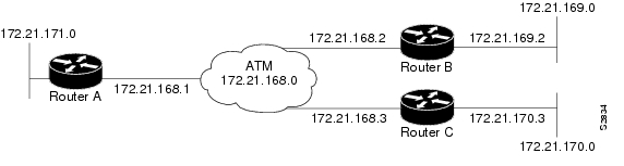
Figure 5-1 illustrates a fully meshed network. The following configuration examples for Routers A, B, and C follow the figure. In this example, the routers are configured to use PVCs. Fully meshed indicates that each network node has either a physical circuit or a virtual circuit connecting it to every other network node. The two map-list statements configured in Router A identify the ATM addresses of Routers B and C. The two map-list statements in Router B identify the ATM addresses of Routers A and C. The two map list statements in Router C identify the ATM addresses of Routers A and B.
Figure 5-1 Fully Meshed ATM Configuration Example
Router A
ip routing
!
interface atm 4/0
ip address 131.108.168.1 255.255.255.0
atm pvc 1 0 10 aal5snap
atm pvc 2 0 20 aal5snap
map-group test-a
!
map-list test-a
ip 131.108.168.2 atm-vc 1 broadcast
ip 131.108.168.3 atm-vc 2 broadcast
Router B
ip routing
!
interface atm 2/0
ip address 131.108.168.2 255.255.255.0
atm pvc 1 0 20 aal5snap
atm pvc 2 0 21 aal5snap
map-group test-b
!
map-list test-b
ip 131.108.168.1 atm-vc 1 broadcast
ip 131.108.168.3 atm-vc 2 broadcast
Router C
ip routing
!
interface atm 4/0
ip address 131.108.168.3 255.255.255.0
atm pvc 2 0 21 aal5snap
atm pvc 4 0 22 aal5snap
map-group test-c
!
map-list test-c
ip 131.108.168.1 atm-vc 2 broadcast
ip 131.108.168.2 atm-vc 4 broadcast
Example of SVCs in a Fully Meshed Network
The following example is also a configuration for the fully meshed network shown in Figure 5-1, but using SVCs. PVC 1 is the signaling PVC.
Router A
interface atm 4/0
ip address 131.108.168.1 255.255.255.0
map-group atm
atm nsap-address AB.CDEF.01.234567.890A.BCDE.F012.3456.7890.1234.12
atm pvc 1 0 5 qsaal
!
map-list atm
ip 131.108.168.2 atm-nsap BC.CDEF.01.234567.890A.BCDE.F012.3456.7890.1334.13
ip 131.108.168.3 atm-nsap BC.CDEF.01.234567.890A.BCDE.F012.3456.7890.1224.12
Router B
interface atm 2/0
ip address 131.108.168.2 255.255.255.0
map-group atm
atm nsap-address BC.CDEF.01.234567.890A.BCDE.F012.3456.7890.1334.13
atm pvc 1 0 5 qsaal
!
map-list atm
ip 131.108.168.1 atm-nsap AB.CDEF.01.234567.890A.BCDE.F012.3456.7890.1234.12
ip 131.108.168.3 atm-nsap BC.CDEF.01.234567.890A.BCDE.F012.3456.7890.1224.12
Router C
interface atm 4/0
ip address 131.108.168.3 255.255.255.0
map-group atm
atm nsap-address BC.CDEF.01.234567.890A.BCDE.F012.3456.7890.1224.12
atm pvc 1 0 5 qsaal
!
map-list atm
ip 131.108.168.1 atm-nsap AB.CDEF.01.234567.890A.BCDE.F012.3456.7890.1234.12
ip 131.108.168.2 atm-nsap BC.CDEF.01.234567.890A.BCDE.F012.3456.7890.1334.13
Example of Connecting Two ATM Port Adapters Back-to-Back
Two routers, each containing a PA-A1 ATM can be connected directly with a standard cable, which allows you to verify the operation of the ATM port or to directly link the routers in order to build a larger node.
Define Cisco 7500 series interfaces by interface type and physical slot or port location. The show interfaces command displays the logical unit number in the router and the physical slot or port location in the Cisco 7500 series router. For complete configuration descriptions and examples, refer to the router software publications appropriate for your Cisco IOS software release.
To connect two routers, attach the cable between the ATM port on each.
By default, the PA-A1 ATM expects a connected ATM switch to provide transmit clocking. To have the PA-A1 ATM generate the transmit clock internally for SONET physical layer interface module (PLIM) operation, add the atm clock internal command to your configuration.
Note ![]() For SONET interfaces, one of the ATM port adapters in each router must be configured to supply its internal clock to the line.
For SONET interfaces, one of the ATM port adapters in each router must be configured to supply its internal clock to the line.
Following is an example of configuration file commands for two routers connected through their SONET interface:
First router:
interface ATM3/0
ip address 192.168.1.10 255.0.0.0
no keepalive
map-group atm-in
atm clock internal
atm pvc 1 1 5 aal5snap
!
map-list atm-in
ip 192.168.1.20 atm-vc 1 broadcast
Second router:
interface ATM3/0
ip address 192.168.1.20 255.0.0.0
no keepalive
map-group atm-in
atm clock internal
atm pvc 1 1 5 aal5snap
!
map-list atm-in
ip 192.168.1.10 atm-vc 1 broadcast
This completes the PA-A1 ATM interface installation and configuration.
Using the ping Command to Verify Network Connectivity
Using the ping command, you can verify that an interface port is functioning properly. This section provides brief descriptions of this command. Refer to the publications listed in the "Related Documentation" section for detailed command descriptions and examples.
The ping command sends echo request packets out to a remote device at an IP address that you specify. After sending an echo request, the command waits a specified time for the remote device to reply. Each echo reply is displayed as an exclamation point (!) on the console terminal; each request that is not returned before the specified timeout is displayed as a period (.). A series of exclamation points (!!!!!) indicates a good connection; a series of periods (.....) or the messages [timed out] or [failed] indicate a bad connection.
Following is an example of a successful ping command to a remote server with the address 10.0.0.10:
Router# ping 10.0.0.10
Type escape sequence to abort.
Sending 5, 100-byte ICMP Echoes to 10.0.0.10, timeout is 2 seconds:
!!!!!
Success rate is 100 percent (5/5), round-trip min/avg/max = 1/15/64 ms
Router#
If the connection fails, verify that you have the correct IP address for the destination and that the device is active (powered up), and repeat the ping command.
Proceed to the next section "Configuring an ATM Interface for Local Loopback" to finish checking network connectivity.
Configuring an ATM Interface for Local Loopback
To configure an ATM interface for local loopback (useful for checking that the PA-A1 ATM is working), use the following command:
Router# loopback diagnostic
Router# no loopback diagnostic
The no form of the command turns off local loopback.
To configure an ATM interface for external loopback, use the following command:
Router# loopback line
Router# no loopback line
The no form of the command turns off external loopback at the line.
 Feedback