- About This Guide
- Before You Begin
- Getting Started with Cisco Vision Dynamic Signage Director Operation
- Working with TV Displays
- Working with Zones, Groups, and Locations
- Working with Content Deployment
- Working with Screen Templates in Cisco Vision Director
- Working with Content in Cisco Vision Director
- Working with Playlists in Cisco Vision Director
- Working with Video Walls
- Working with Event Scripts
- Monitoring Media Player Operation During an Event Using Device Management
- Troubleshooting Event Operations in Cisco Vision Director
- Managing System Services in Cisco Vision Director
- Managing Server Resources in Cisco Vision Director
- Managing Media Player Operation in Cisco Vision Director
- Managing Backups in Cisco Vision Director
- Glossary of Terms
Release 6.3: Cisco Vision Dynamic Signage Director Operations Guide
Bias-Free Language
The documentation set for this product strives to use bias-free language. For the purposes of this documentation set, bias-free is defined as language that does not imply discrimination based on age, disability, gender, racial identity, ethnic identity, sexual orientation, socioeconomic status, and intersectionality. Exceptions may be present in the documentation due to language that is hardcoded in the user interfaces of the product software, language used based on RFP documentation, or language that is used by a referenced third-party product. Learn more about how Cisco is using Inclusive Language.
- Updated:
- August 5, 2020
Chapter: Working with TV Displays
Working with TV Displays
User Role: Administrator, Venue Administrator
This module provides information about setting up TV displays in Cisco Vision Director.
User TV Control
Support for all methods of user TV control is enabled by default in Cisco Vision Director for all media player types. This includes control of TV displays using local control devices and applications, IP phones, touch screens and infrared remote (IR) control.
Some venues have a need to disable user TV control for certain events or suites, or to limit the TV to display a particular channel or control its volume.
New TV Control Access
We are upgrading our UI and improving your access. We added a new icon to the Configuration interface (Figure 1). Previously, this portal was available through a separate interface. Full functionality remains.

This interface is particularly powerful when you have zones and groups of devices to power off. Using the Zones & Groups interface is discussed fully in Working with Zones, Groups, and Locations.
1.![]() Select an Available Zone from the list in the left panel.
Select an Available Zone from the list in the left panel.
2.![]() Click the Left motion arrow to Assign that Available Zone to the Assigned Zones list. Use the Control and Shift Control keys to select specific zones or ranges of zones to move from one list to the other.
Click the Left motion arrow to Assign that Available Zone to the Assigned Zones list. Use the Control and Shift Control keys to select specific zones or ranges of zones to move from one list to the other.
3.![]() Click Cancel to undo recent changes.
Click Cancel to undo recent changes.
4.![]() Click Save. If you do not click Save, all your changes are lost. No warning box appears.
Click Save. If you do not click Save, all your changes are lost. No warning box appears.
If the changes do not appear, click the Refresh icon in the top left. A Confirmation Refresh box appears (Figure 2).
Both lists are fully sortable. Click Name to sort.
Figure 2 Confirm Refresh of Assigning Zones

To turn off the TVs in a zone:
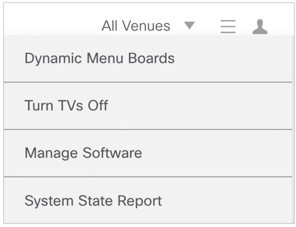
1.![]() Select More > Turn TVs Off (Figure 3). The Confirmation dialog box appears (Figure 3).
Select More > Turn TVs Off (Figure 3). The Confirmation dialog box appears (Figure 3).

The Info dialog box appears to tell you the Turn TVs Off command was sent successfully to Cisco Vision Director. Following that, an auto-generated email is sent to the role that performed the action (Figure 5).
Figure 5 Notification Email of TV Off

TV Display Specification
Cisco Vision Director requires that you configure certain commands and attributes for the TVs used in the venue to ensure proper communication between the media player and the TV. This configuration is defined in what is called a display specification.
By default, Cisco Vision Director includes display specifications for several common TV display models. If your TV display model is not included in the default specifications, add and configure it.
A different display specification is required for each unique TV type, based on which commands are used to control the TVs. In some cases, all TVs from a certain manufacturer can use the same display specifications. In other cases, different TV models from the same company might require different display specifications.
Note : As a best practice, configure your TV display specifications before configuring Locations in Cisco Vision Director. You must select the “Display Spec” for the type of TV (brand/model) that is physically installed when you configure a Location.
Closed Captioning
The standard for closed captioning (CC) in North America, which all digital TV broadcasters typically follow, is the Consumer Electronics Association (CEA)-608 and CEA-708 closed captioning standard. Figure 6 shows US CC standards.
IMPORTANT : Closed Captioning will not work in Europe or anywhere outside of North America.
Figure 6 Closed Captioning Support in Cisco Vision Dynamic Signage Director
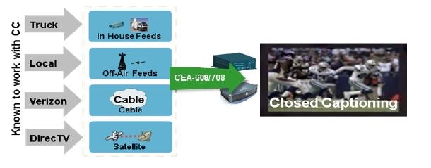
This standard is generally supported on all broadcast channels from service providers. Cisco Vision Director is automatically configured to enable closed captioning CC1–CC4 support on the Cisco devices.
Content Orientation
The default orientation for all content in Cisco Vision Director is landscape mode.
You can manually create content in vertical format (static graphics only) and rotate it. Set auto-rotation of content in portrait mode in the TV Display Specification.
Guidelines for Portrait Mode Auto-Rotation
■![]() Allows DMPs to automatically rotate content for proper orientation on vertically-positioned displays.
Allows DMPs to automatically rotate content for proper orientation on vertically-positioned displays.
■![]() Supported for all content sources for a single TV display.
Supported for all content sources for a single TV display.
■![]() Scaling of content across multiple display screens in portrait mode is only supported for multicast streaming video.
Scaling of content across multiple display screens in portrait mode is only supported for multicast streaming video.
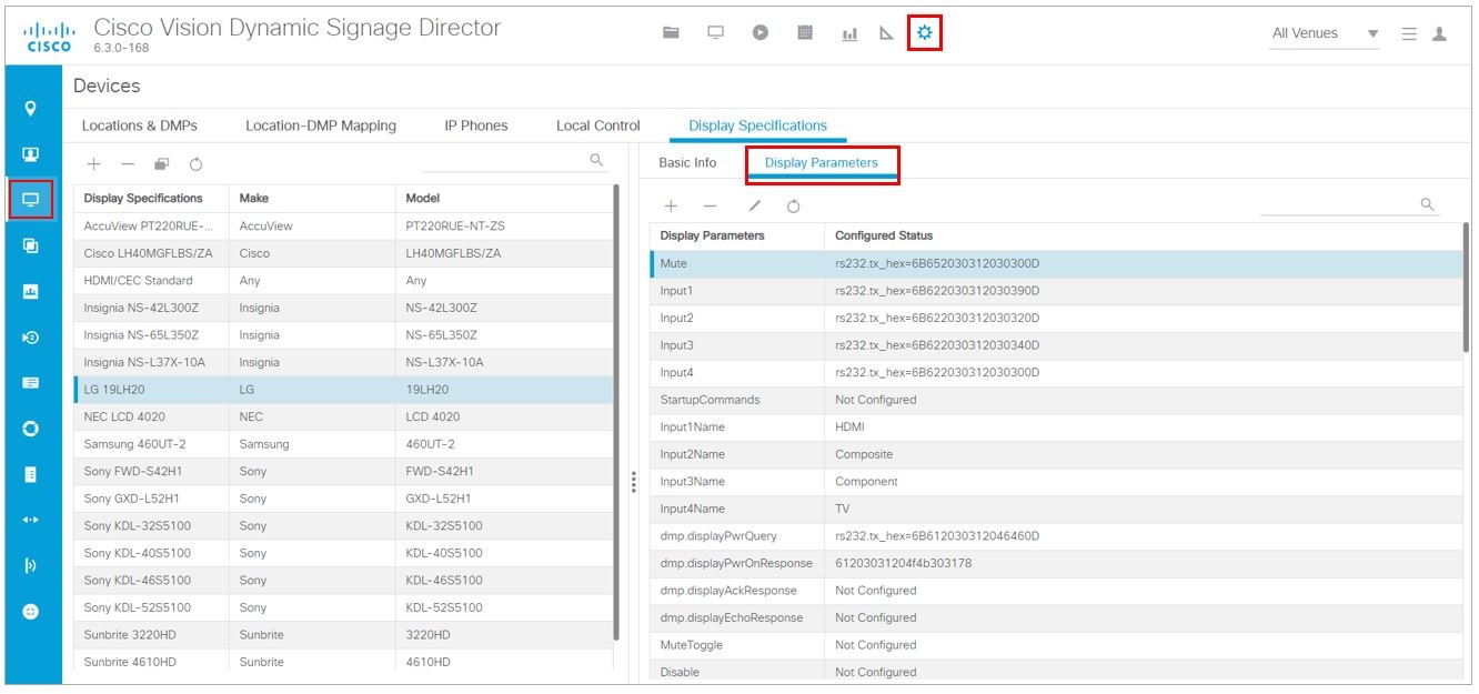
■![]() Enabled using the “dmp.portrait=true” Display Parameter when configuring TV Display Specifications in the Configuration > Devices interface (Figure 7).
Enabled using the “dmp.portrait=true” Display Parameter when configuring TV Display Specifications in the Configuration > Devices interface (Figure 7).
Note : DMP portrait mode is not available for UHD (4K) videos. See the Cisco Vision Content Planning and Specifications Guide, Release 6.3 for complete information about using portrait mode and auto-rotation.
IMPORTANT : When planning for portrait video playout, consider all other secondary system tasks such as:
–![]() Graphics operations like tickers, HTML graphics, and large image files
Graphics operations like tickers, HTML graphics, and large image files
–![]() Network traffic (doing large/frequent networked updates)
Network traffic (doing large/frequent networked updates)
These tasks interact with the hardware restrictions on your DMP. Reduce or eliminate these secondary tasks or upgrade to a higher performance DMP model.
Content rotation requires a significant amount of processing, so playback performance is not equal to landscaped display. Table 1 shows some basic guidelines for the Cisco Vision DMPs.
Note: Portrait mode is not recommended for CV-HD and CV-HD2 DMPs. For the CV-UHD and CV-UHD2 players, single or dual video playback will likely perform well, but may exhibit playback issues.
IMPORTANT: Test your video sources against your players to ensure that video dimensions and video encoding are satisfactory during playback.
Flexible DMP Content Rotation
You can rotate content 90 degrees and -90 degrees (or +270 degrees). This works for all content like videos, static images, widgets, local and multicast video, and external URLs. Rotate content for situations where the display monitor has already been installed in a portrait position and to show your content in the proper orientation.
To rotate content to portrait mode:
1.![]() Click Configuration > Devices > Display Specifications.
Click Configuration > Devices > Display Specifications.
2.![]() Choose the specific display from the list on the left panel and click the Display Parameters tab in the right panel (Figure 7).
Choose the specific display from the list on the left panel and click the Display Parameters tab in the right panel (Figure 7).
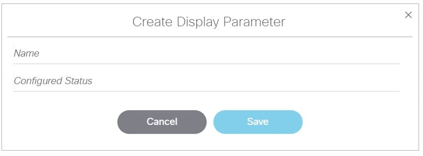
3.![]() Click + to add a new Display Parameter. The Create Display Parameter dialog box appears (Figure 8).
Click + to add a new Display Parameter. The Create Display Parameter dialog box appears (Figure 8).
Figure 7 Adding Content Rotation Specifics to Display Parameters
4.![]() Type dmp.portrait or dmp.portrait.clockwise and set it to “ true ” to achieve the proper rotation value you need.
Type dmp.portrait or dmp.portrait.clockwise and set it to “ true ” to achieve the proper rotation value you need.
Figure 8 Create New Display Parameter
By default, if you use dmp.portrait and set “true” to your content, it rotates the content 90 degrees. If you set dmp.portrait.clockwise to “true,” it will rotate the content 270 degrees (or -90 degrees).
Note : Reboot the DMPs to set this parameter. Click Configuration > System Configuration > System Tasks > Reboot DMP Task.
Below is a figure displaying rotated content 90 and -90 degrees. Use clockwise and counterclockwise.

Distorted Portrait Mode Displays
IMPORTANT: When the DMP is in portrait mode and you are streaming a multicast video, you may notice that the display is distorted. If this happens, it may be because the DMP registry of scaleToFit.video is set to “ true.” The default is this registry is not present or it is set to “false.” If there is an outstanding reason to have the registry set to true, then change the default from a multicast stream with portrait mode URL to something else, like a web page instead.
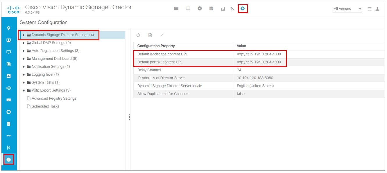
To set a separate default URL for portrait-oriented displays:
1.![]() Click Configuration > System Configuration > Dynamic Signage Director Settings.
Click Configuration > System Configuration > Dynamic Signage Director Settings.
2.![]() Change the Value of the Default portrait content URL to use HTML so the content is not stretched.
Change the Value of the Default portrait content URL to use HTML so the content is not stretched.
HDMI-CEC
Support for HDMI Consumer Electronics Control (CEC) allows you to control the following three TV functions:
When HDMI CEC TV control is enabled, HDMI CEC is used instead of RS-232 for TV control functions. To control TVs, run the TV On and TV Off commands from the Device Management interface. Use the Get Status drop-down arrow.
Configure a TV display for HDMI-CEC TV control using one of two methods:
■![]() Apply the HDMI/CEC Standard display specification for new TVs, where the HDMI-CEC display parameters are automatically enabled and set to default values.
Apply the HDMI/CEC Standard display specification for new TVs, where the HDMI-CEC display parameters are automatically enabled and set to default values.
■![]() Modify an existing display specification to set the HDMI-CEC display parameters manually.
Modify an existing display specification to set the HDMI-CEC display parameters manually.
The following commands are used by HDMI/CEC TV control:
■![]() dmp.powerQueryByCEC—Enables powerQuery to get TV Power status using HDMI/CEC instead of RS-232.
dmp.powerQueryByCEC—Enables powerQuery to get TV Power status using HDMI/CEC instead of RS-232.
■![]() dmp.TVControlbyCEC—Enables TV control using HDMI/CEC instead of RS-232.
dmp.TVControlbyCEC—Enables TV control using HDMI/CEC instead of RS-232.
■![]() dmp.monitorAPIDelay—Frequency of power query command sent by Dynamic Signage Director over HDMI CEC to the TV. The default is 120000 ms (2 minutes). This command is also supported when using TV control with RS-232.
dmp.monitorAPIDelay—Frequency of power query command sent by Dynamic Signage Director over HDMI CEC to the TV. The default is 120000 ms (2 minutes). This command is also supported when using TV control with RS-232.
■![]() dmp.monitorPower—Enables Dynamic Signage Director to run a power query to the TV using the Get Status command from Device Management. This command is also supported when using TV control with RS-232.
dmp.monitorPower—Enables Dynamic Signage Director to run a power query to the TV using the Get Status command from Device Management. This command is also supported when using TV control with RS-232.
■![]() dmp.hdmiStreamingDelay —Indicates the amount of time (units in ms) that the DMP will stop streaming from the time it receives the command. If not defined, the default is 500 (ms). Typically, you do not need to define this parameter.
dmp.hdmiStreamingDelay —Indicates the amount of time (units in ms) that the DMP will stop streaming from the time it receives the command. If not defined, the default is 500 (ms). Typically, you do not need to define this parameter.
For HDMI Streaming operations initiated via IR Remote, this parameter prevents too frequent commands from crashing the DMP. If no value is set for this parameter through the Display Specifications, the default is 5000 milliseconds.
This is similar to the parameter “Ratelimit.Frequency.High.” The only difference being that this parameter is for HDMI Streaming operations issued through local control API.
TV Qualification for HDMI-CEC Support
Note: Not all TVs support the standard HDMI-CEC commands. Test the TV models that you plan to install for support of HDMI CEC. Turn on HDMI-CEC. TV manufacturers refer to CEC by different trade names. For example, Anynet+ (Samsung), BRAVIALink (Sony), EasyLink (Phillips), and SimpLink (LG).
Note : HDMI-CEC does not support the same command set as RS-232 due to proprietary links.
For more information about the successfully tested TV for HDMI CEC, see the Cisco Vision Dynamic Signage Director Release Notes for Release 6.0.
Display Parameters for RS-232 Communication
RS-232 commands can be used to control TV functions such as On/Off, mute, volume and external input. In more specialized scenarios they might also be used to configure TV tile matrix capabilities.
RS-232 responses are used to retrieve the current status of a TV. Currently Cisco Vision Director uses responses only when querying a TV for its current power on/off status.
For situations where a TV cannot be controlled via RS-232 or otherwise, volume and mute can be controlled by the media player instead. This is behavior is indicated by configuring volume and mute commands that start with sigma=.
Display Parameters for RS-232 TV Control
Table 3 shows a summary of the display parameters and RS-232 commands for the DMPs with their example values. These values are provided as an example of the type of data you would enter.
Note : Different TV display models may support only certain RS-232 commands. The commands in this table are supported by the LG 19LH20 TV display. Each model and even software version of a display may require a different configuration.
IMPORTANT: Check with the TV display manufacturer for the appropriate values to enter.
Table 3 DMP Display Parameters
Volume Control
When properly configured in Cisco Vision Director, volume changes can be made from methods such as the IP phone, IR remote, Device Management, or event script state change. Volume changes for the primary video audio can be controlled for the SPDIF (on the SV-4K, CV-UHD, and CV-UHD2 only), analog audio, and HDMI out ports only when the TV display specification volume strategy is set to internal.
Volume Strategy Option
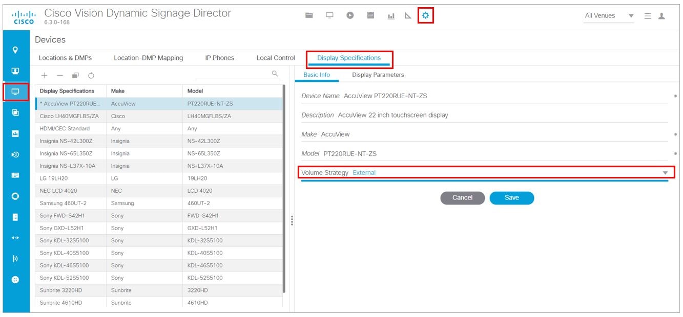
Cisco Vision Director supports three Volume Strategy settings, see Figure 9.
To choose the volume for the device:
1.![]() Go to Configuration > Devices > Display Specifications > Basic Info.
Go to Configuration > Devices > Display Specifications > Basic Info.
2.![]() Use the Volume Strategy pull-down arrow to choose a volume.
Use the Volume Strategy pull-down arrow to choose a volume.
Figure 9 Display Specifications—Volume Strategy Option
Internal—The audio feed volume level is controlled by telling the DMP how loud to send the signal. Internal allows volume change control of the audio feed by Cisco Vision Director (such as by the IP phone, IR remote, Device Management, or event script state).
External—Using External, the level sent by the DMP remains the same and the DMP sends commands to change the volume level on the attached TV, via RS-232.
Note: We recommend external volume strategy because most TVs have better audio range than the DMP and many TVs show a visual indicator of the volume as it changes. This strategy also avoids problems if someone changes the volume using the TV panel buttons or the TV remote.
None—The volume cannot be adjusted. This is useful for TVs that are used for video only where audio (if any) is provided separately (such as in a bar where an overhead system provides the audio).
How to Configure TV Display Specifications
This section includes the following topics:
■![]() Guidelines for RS-232 Command Configuration
Guidelines for RS-232 Command Configuration
■![]() Configuring Basic Information for TV Display Specifications,
Configuring Basic Information for TV Display Specifications,
■![]() Configuring Touchscreen Support
Configuring Touchscreen Support
■![]() Configuring Touchscreen Support
Configuring Touchscreen Support
Guidelines for RS-232 Command Configuration
Consider the following guidelines when configuring RS-232 commands in TV display specifications:
■![]() Cisco Vision Director supports only one RS-232 command per event state.
Cisco Vision Director supports only one RS-232 command per event state.
■![]() All RS-232 commands configured in Cisco Vision Director must use the prefix rs232.tx_hex=.
All RS-232 commands configured in Cisco Vision Director must use the prefix rs232.tx_hex=.
■![]() RS-232 responses are used to retrieve the current status of a TV.
RS-232 responses are used to retrieve the current status of a TV.
■![]() RS-232 responses are always configured without a prefix.
RS-232 responses are always configured without a prefix.
■![]() Cisco Vision Director uses responses only when querying a TV for its current power on/off status.
Cisco Vision Director uses responses only when querying a TV for its current power on/off status.
■![]() For situations where a TV cannot be controlled via RS-232 or otherwise, volume and mute can be controlled by the media player instead.
For situations where a TV cannot be controlled via RS-232 or otherwise, volume and mute can be controlled by the media player instead.
Configuring Basic Information for TV Display Specifications
To configure basic information for TV display specifications:
1.![]() Go to Configuration > Devices > Display Specifications (Figure 9).
Go to Configuration > Devices > Display Specifications (Figure 9).
■![]() Select an existing display specification.
Select an existing display specification.
■![]() Click the + icon to add a new display specification.
Click the + icon to add a new display specification.
3.![]() Refer to Table 4 to specify the options in the Basic Info panel.
Refer to Table 4 to specify the options in the Basic Info panel.
Table 4 Basic TV Display Specification Options
|
|
|
|---|---|
|
|
|
|
|
|
|
|
|
|
|
|
|
|
|
Configuring HDMI-CEC TV Control in TV Display Specifications
User Role: Administrator, Venue Administrator
You can apply the HDMI/CEC Standard display specification for new TVs, or you can modify an existing display specification to add the display parameters commands independently.
If you use the HDMI/CEC Standard display specification, the four related HDMI-CEC commands for TV control are enabled and set to any corresponding default value.
To configure HDMI-CEC display parameters:
1.![]() Go to Configuration > Devices > Display Specifications.
Go to Configuration > Devices > Display Specifications.
2.![]() Select an existing display specification or add a new one.
Select an existing display specification or add a new one.
3.![]() Click Display Parameters tab.
Click Display Parameters tab.
4.![]() Find and set the following parameters:
Find and set the following parameters:
Note : You can run the Get Status command from Device Management to get the latest TV health status known to the DMP. This information can be up to two minutes old, or a few seconds depending on when the power query last ran.
If the “ dmp.monitorPower ” parameter is set to false then you will not get the correct TV health status.
Configuring Touchscreen Support
For proper touchscreen operation with HTML5 pages, be sure that your touchscreen devices are human interface device (HID)-compliant and are using standard HID drivers.
Note: Some manufacturers claim support for HID while using custom drivers. Verify that standard HID drivers are used.
By default, the display parameter is set to false for Cisco Vision Director. To enable touchscreen capability between your device and the DMP, you must change that.
To enable touchscreen capabilities for your specific device:
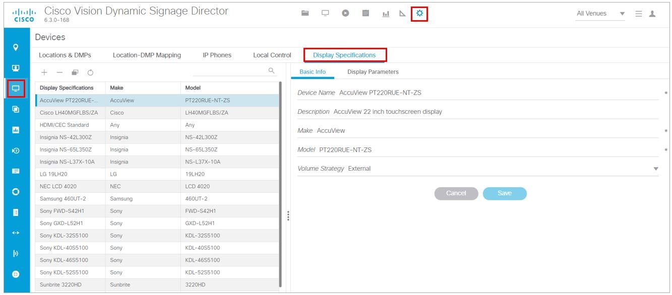
1.![]() In Cisco Vision Director, go to Configuration > Devices > Display Specifications (Figure 10).
In Cisco Vision Director, go to Configuration > Devices > Display Specifications (Figure 10).
Figure 10 Setting Display Specifications
2.![]() Create a display specification for your device screen. See the device specifications for this information. Use the + icon to create a new spec.
Create a display specification for your device screen. See the device specifications for this information. Use the + icon to create a new spec.
Or, scroll down the list of devices. Find your Make and Model and select it.
3.![]() Click the Display Parameters tab.
Click the Display Parameters tab.
4.![]() Scroll down to dmp.SupportsTouchScreen and select it.
Scroll down to dmp.SupportsTouchScreen and select it.
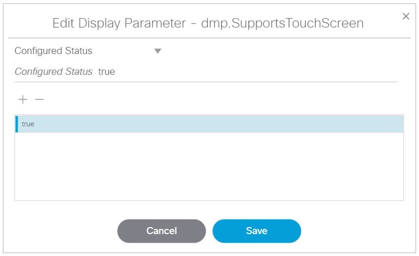
5.![]() Click the Edit icon. The Edit Display Parameter box appears (Figure 11).
Click the Edit icon. The Edit Display Parameter box appears (Figure 11).
6.![]() In the Display Parameter Edit box, change false to “ true ” for your device.
In the Display Parameter Edit box, change false to “ true ” for your device.
Figure 11 Edit Display Parameter Dialog Box
By enabling this feature, you are giving touch screen support to a state or a channel to your content (generally an HTML page).
To connect the DMP to your device:
Use a USB A to B-type cable that connects from the DMP USB port to your device.
Configuring Display Parameters for External Volume Support
When using the external volume strategy, configure RS-232 commands to send to the TV to change the volume (Figure 12).
Click Configuration > Devices > Display Specifications > Basic Info > Volume Strategy > External.
Figure 12 External Volume Strategy
Note : When using internal volume strategy, volume commands do not need to be configured.
Cisco Vision Director allows you to configure two types of volume controls:
■![]() Relative—Depends on the volume increments set in the TV, which vary from model to model.
Relative—Depends on the volume increments set in the TV, which vary from model to model.
■![]() Absolute—Preferred method. Defines a number of increments that are used to control the volume between the minimum and maximum volume levels.
Absolute—Preferred method. Defines a number of increments that are used to control the volume between the minimum and maximum volume levels.
–![]() For the SV-4K—Absolute volume is configured only by the series of Volumen commands only.
For the SV-4K—Absolute volume is configured only by the series of Volumen commands only.
Table 5 provides information about the display parameters used to configure the Relative and Absolute types of external volume control.
Table 5 Display Parameters for External Volume Support
Table 6 shows an example of RS-232 command strings defined for Absolute volume control using 12 increments.
Table 6 Volume Count Command Example for One Model of LG TV Display
How to Configure the TV Display Banner
This section includes the following topics:
■![]() Setting the Display Input Name
Setting the Display Input Name
■![]() Disabling the TV Display Banner
Disabling the TV Display Banner
Setting the Display Input Name
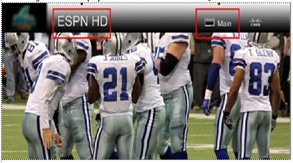
The TV display banner is a graphical banner that temporarily appears at the top of the display to provide information about the TV that received a TV command (Figure 15).
To set the TV display name so it appears on screen:
1.![]() Click Configuration > Luxury Suites.
Click Configuration > Luxury Suites.
2.![]() Click the + icon to add a luxury suite or select an existing one.
Click the + icon to add a luxury suite or select an existing one.
3.![]() Fill in the required fields.
Fill in the required fields.
5.![]() Click the Location Assignment tab (Figure 13). The screen shows the Assigned Locations and the Available Locations panels.
Click the Location Assignment tab (Figure 13). The screen shows the Assigned Locations and the Available Locations panels.
6.![]() Highlight a Location Name from the right panel and click the Assign Location. Now that Location appears in the Assigned Locations panel.
Highlight a Location Name from the right panel and click the Assign Location. Now that Location appears in the Assigned Locations panel.
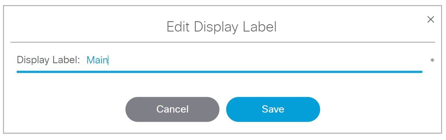
7.![]() Click the Edit (pencil icon). The Edit Display Label box appears (Figure 14).
Click the Edit (pencil icon). The Edit Display Label box appears (Figure 14).
8.![]() Type a name in the Display Label field, in our example “Main” (Figure 15).
Type a name in the Display Label field, in our example “Main” (Figure 15).
Figure 13 Assign the Location of the Luxury Suite
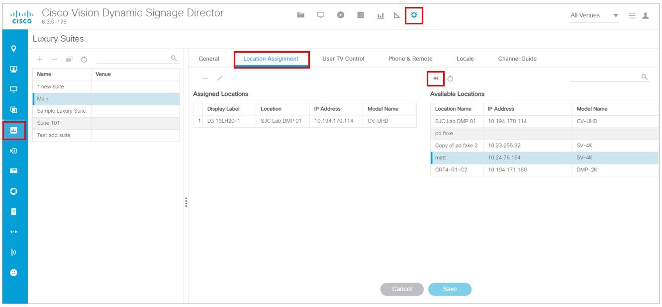
Figure 14 Setting the Display Name
9.![]() Click Save to close the dialog box.
Click Save to close the dialog box.
10.![]() Click Save for the suite configuration.
Click Save for the suite configuration.
Note: The change will not reflect on the DMP until the next content push or a DMP restart.
The display banner is enabled by default with a duration of 5 seconds when controlled via the IR Remote (Figure 15).
Figure 15 TV Display Banner and Screen Identification
Disabling the TV Display Banner
For a better visual experience for video wall displays, disable the TV display banner. The TV display banner is enabled by default for all TV displays.
To disable the TV display banner globally:
1.![]() Click Configuration > System Configuration > Advanced Registr y Settings.
Click Configuration > System Configuration > Advanced Registr y Settings.
Scroll to see if localControl.banner.disable has been added. If it has and the value is not true, click Edit.
2.![]() In the Registry Data box, click + (Add). The Create Configuration Setting dialog box appears.
In the Registry Data box, click + (Add). The Create Configuration Setting dialog box appears.
3.![]() In the Key field, type localControl.banner.disable.
In the Key field, type localControl.banner.disable.
 Feedback