Cisco Vision Network, Server, and Video Headend Requirements Guide, Release 6.3
Bias-Free Language
The documentation set for this product strives to use bias-free language. For the purposes of this documentation set, bias-free is defined as language that does not imply discrimination based on age, disability, gender, racial identity, ethnic identity, sexual orientation, socioeconomic status, and intersectionality. Exceptions may be present in the documentation due to language that is hardcoded in the user interfaces of the product software, language used based on RFP documentation, or language that is used by a referenced third-party product. Learn more about how Cisco is using Inclusive Language.
- Updated:
- October 28, 2020
Chapter: Headend Section of the Cisco Vision Solution
Headend Section
Cisco Vision Director is a proven, end-to-end, high-definition IPTV solution that provides advanced video content management and delivery. It is a centrally managed, video processing and distribution solution that enables the integration and automated delivery of customized and dynamic content from multiple sources to different monitor displays in High Definition (HD), or Ultra High Definition (UHD) local video.
Cisco Vision Director is purpose-built for large venues, retailers, hospitality providers, and transportation hubs which have extensive video systems deployed throughout and is designed to enhance the viewing of live events, multimedia information, and dynamic content. In addition, it leverages video systems in restaurants, clubs, and luxury suites to allow customers to view both in-house programming as well as external network channels.
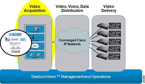
Cisco Vision Director comprises four major components, as shown in Figure 1.
■![]() Video acquisition (or video headend)
Video acquisition (or video headend)
■![]() Converged voice, video, and data high-speed IP network
Converged voice, video, and data high-speed IP network
■![]() Video delivery (and digital signage playback)
Video delivery (and digital signage playback)
■![]() Centralized management and operations
Centralized management and operations
Figure 1 Cisco Vision Major Components
Functional Overview
The headend is designed to acquire, process, and encode the video content used in the Cisco Vision Director solution. Figure 2 provides a simplified view of the video headend design, incorporating multiple types of video sources.
Figure 2 Headend Functional Elements
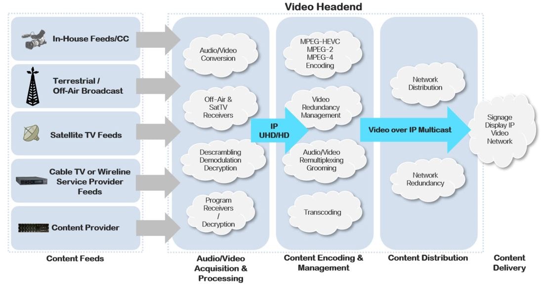
In the headend, the video feed is:
■![]() Provided by multiple sources.
Provided by multiple sources.
■![]() Acquired and processed through the appropriate receivers and decrypters.
Acquired and processed through the appropriate receivers and decrypters.
■![]() Encoded using an HD (H.264/MPEG-4) or UHD (H.265) encoder.
Encoded using an HD (H.264/MPEG-4) or UHD (H.265) encoder.
■![]() Groomed and aggregated using a standards-based MPEG multiplexer
Groomed and aggregated using a standards-based MPEG multiplexer
■![]() Sent using multicast to the IP network.
Sent using multicast to the IP network.
Once the multicast stream is on the network, the DMP can join it via IGMP and display it on the corresponding TV.
The Cisco Vision headend provides support for:
■![]() High-definition (HD) and Ultra High Definition (UHD) channel lineup with delivery of H.262 (MPEG-2, Part 2) and H.264 (MPEG-4, Part 10) and H.265 (HEVC) into the video distribution plant.
High-definition (HD) and Ultra High Definition (UHD) channel lineup with delivery of H.262 (MPEG-2, Part 2) and H.264 (MPEG-4, Part 10) and H.265 (HEVC) into the video distribution plant.
■![]() Terrestrial TV (also called Off-Air or Free-to-Air) video feeds.
Terrestrial TV (also called Off-Air or Free-to-Air) video feeds.
■![]() Encrypted video feeds from a cable or satellite provider.
Encrypted video feeds from a cable or satellite provider.
■![]() Direct IP feeds from cable provider or from DirecTV receivers (as in North America).
Direct IP feeds from cable provider or from DirecTV receivers (as in North America).
■![]() Encoded external video sources. The DMP as an encoder can provide this function
Encoded external video sources. The DMP as an encoder can provide this function
■![]() Support for standards-based MPEG multiplexer and the native features it offers for changing video and audio feeds in the headend core.
Support for standards-based MPEG multiplexer and the native features it offers for changing video and audio feeds in the headend core.
■![]() A fixed channel lineup where each video channel is set to an IP Multicast address.
A fixed channel lineup where each video channel is set to an IP Multicast address.
Headend Reference Architectures
Cisco Vision Director includes two options for headend architecture:
■![]() Standard (recommended) architecture, which provides redundancy with failover to ensure high availability.
Standard (recommended) architecture, which provides redundancy with failover to ensure high availability.
■![]() Baseline architecture, which provides a lower-cost entry point that can be modified at a later date to incorporate the redundancy and failover of the standard architecture.
Baseline architecture, which provides a lower-cost entry point that can be modified at a later date to incorporate the redundancy and failover of the standard architecture.
Note: Generally speaking, this document assumes a standard (redundant) architecture.
Baseline Architecture
The baseline architecture (Figure 3) provides an entry-level solution for cost- sensitive venues for North America and internationally. In this architecture:
■![]() There is no redundancy. However, the design allows this to be added at a later date.
There is no redundancy. However, the design allows this to be added at a later date.
■![]() The recommended encoding for in-house feeds (HD/UHD) is H.264/H.265.
The recommended encoding for in-house feeds (HD/UHD) is H.264/H.265.
■![]() No provisions are made for to accommodate legacy analog TV or RF plants.
No provisions are made for to accommodate legacy analog TV or RF plants.
■![]() The video distribution switch (VDS) should have dual 10 Gigabit connections to the core switch.
The video distribution switch (VDS) should have dual 10 Gigabit connections to the core switch.
Standard Architecture
■![]() The standard architecture (Figure 3 and Figure 4), is the recommended architecture for Cisco Vision Director deployments. Beyond the baseline architecture, it incorporates redundancy for high availability, as well as support for additional features.
The standard architecture (Figure 3 and Figure 4), is the recommended architecture for Cisco Vision Director deployments. Beyond the baseline architecture, it incorporates redundancy for high availability, as well as support for additional features.
Figure 3 Standard Reference Architecture for North America
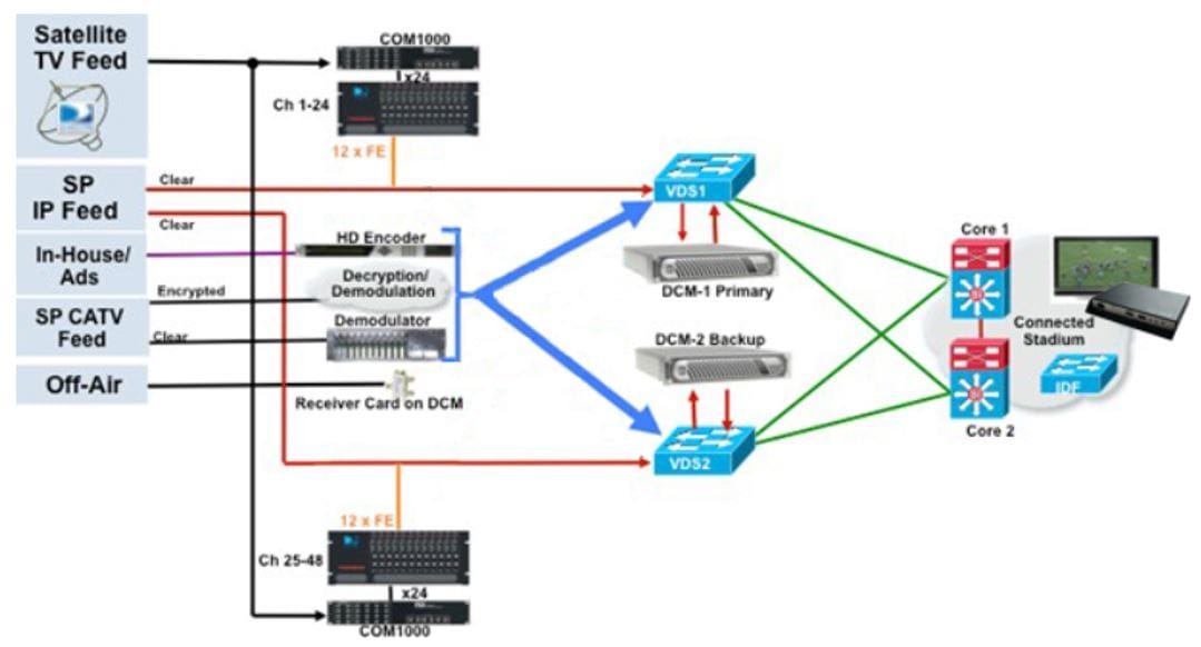
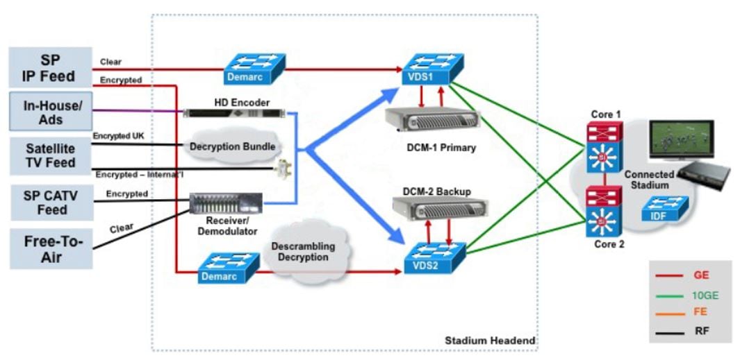
Figure 4 Standard Reference Architecture for International Video Headend Implementations
■![]() Feeds, acquisition devices, processing devices, and video distribution switches are redundant.
Feeds, acquisition devices, processing devices, and video distribution switches are redundant.
■![]() The recommended encoding for in-house feeds (HD/UHD) is H.264/H.265.
The recommended encoding for in-house feeds (HD/UHD) is H.264/H.265.
■![]() The VDS should be deployed in a redundant fashion with dual links to each of the core switches
The VDS should be deployed in a redundant fashion with dual links to each of the core switches
Standards-Based MPEG Multiplexer and Headend Network Infrastructure
Standards-based MPEG multiplexer and the video distribution switches (VDSs) are at the heart of the headend in the Cisco Vision Director solution. While other components of the headend may vary depending on the type of feed, these components remain relatively constant.
■![]() In the baseline head-end design, the core MPEG multiplexer and video distribution switches can be deployed in a non-redundant configuration.
In the baseline head-end design, the core MPEG multiplexer and video distribution switches can be deployed in a non-redundant configuration.
■![]() For improved availability, in the standard headend design the MPEG Multiplexer and the video distribution switches are deployed in a redundant configuration, as previously shown in Figure 3.
For improved availability, in the standard headend design the MPEG Multiplexer and the video distribution switches are deployed in a redundant configuration, as previously shown in Figure 3.
Standards-based MPEG Multiplexer
The standards-based MPEG multiplexer, like Synamedia’s DCM D9902, takes video feeds from the various sources and sends the feeds to the video distribution switch with fixed IP Multicast addresses. The core MPEG Multiplexer can receive either:
■![]() H.262, H.264, or H.265 feeds over Asynchronous Serial Interface (ASI) connections from encoders or demodulators.
H.262, H.264, or H.265 feeds over Asynchronous Serial Interface (ASI) connections from encoders or demodulators.
■![]() H.262, H.264, or H.265 via direct IP feeds (unicast/multicast) from a video provider or from a local source. In this case, the MPEG Multiplexer serves as a demarcation point between the carrier and encoded feeds and the IP video distribution network.
H.262, H.264, or H.265 via direct IP feeds (unicast/multicast) from a video provider or from a local source. In this case, the MPEG Multiplexer serves as a demarcation point between the carrier and encoded feeds and the IP video distribution network.
■![]() Video sources encoded by Harmonic CP9000 encoder should not be passed through the MPEG Multiplexer since it adds 100ms of latency to the path of multicast video.
Video sources encoded by Harmonic CP9000 encoder should not be passed through the MPEG Multiplexer since it adds 100ms of latency to the path of multicast video.
An example of MPEG Multiplexer is Synamedia DCM D9902, but any standards-based MPEG Multiplexer is acceptable.
Video Distribution Switch
The video distribution switch provides the connection between the headend and the converged Cisco IP network. These switches support the advanced features (quality of service, IP Multicast, strict priority queuing) and the performance required for distribution of video streams over an IP network.
The choice of video distribution switch should be based on the required port density, as well as throughput requirements. While PoE is not required for standard operations, it may be needed for video troubleshooting and test points for DMPs located at the headend.
For general switch requirements see Solution Operations and Deployment Requirements.
Redundancy for MPEG Multiplexers in Headend Streams
For redundancy, each HD video channel is sourced from two MPEG Multiplexers, which are configured in an Active-Active setup. The two MPEG Multiplexers act as redundant multicast sources for each channel and connect to separate access routers on Layer 3 interfaces. Although both MPEG Multiplexers are actively sending video streams of the same content, the video streams of the secondary MPEG Multiplexers will only be forwarded on the network in the event of a failure of the primary video stream.
The network is setup for automatic failover of the primary video feed to redundant paths. As shown in Figure 5, if the video feed port on the MPEG Multiplexers Primary fails, the network will converge to the alternate active video feed emitted from the MPEG Multiplexers Secondary (backup). The link between video distribution switches is set with a relatively high EIGRP Delay (in the event of a core-video distribution switch link failure, to force an RPF interface change to the core router).
In the Cisco Vision design, an IP Multicast technique called Prioritycast is used for video multicast. This enables both MPEG Multiplexers to send out exact replicas of the channel lineup using the same IP multicast addresses. Prioritycast is an implementation strategy that provides load sharing and redundancy in Protocol Independent Multicast sparse mode (PIM-SM) networks.
With IGMP-V3 enabled, Source-Specific Multicast is the preferred method which does not require Rendezvous Points (RP) to be configured in the network. But where that option is not available, Prioritycast allows two or more rendezvous points (RPs) to share the load for source registration and the ability to act as hot backup routers for each other. Unlike Anycast, in which clients connect to the closest instance of redundant IP address, with Prioritycast, clients connect to the highest-priority instance of the redundant IP address. This allows for greater control of designating the preferred source.
In the Cisco Vision Director IP multicast implementation:
■![]() The source is the MPEG Multiplexer and the router is the video distribution switch.
The source is the MPEG Multiplexer and the router is the video distribution switch.
■![]() Each multicast channel is assigned the source IP address of the MPEG Multiplexer.
Each multicast channel is assigned the source IP address of the MPEG Multiplexer.
■![]() Each channel is assigned a source prefix of /29 in the IP Multicast address scheme, further divided into a /30. The source (channel) is assigned the lowest of the two host addresses and the router interface is assigned the highest of the two host addresses.
Each channel is assigned a source prefix of /29 in the IP Multicast address scheme, further divided into a /30. The source (channel) is assigned the lowest of the two host addresses and the router interface is assigned the highest of the two host addresses.
■![]() Each MPEG Multiplexer uses the same source IP address but with different prefixes (i.e., /29 and /30).
Each MPEG Multiplexer uses the same source IP address but with different prefixes (i.e., /29 and /30).
■![]() The MPEG Multiplexer with the most specific (highest priority) prefix (i.e., /30) is the primary MPEG Multiplexer serving the network.
The MPEG Multiplexer with the most specific (highest priority) prefix (i.e., /30) is the primary MPEG Multiplexer serving the network.
■![]() The primary servers and RPs are on the same video distribution switch using the /30 network mask.
The primary servers and RPs are on the same video distribution switch using the /30 network mask.
In this design, the Reverse Path Forwarding (RPF) interfaces are determined using the installed unicast route of the longest advertised RP and sources prefixes. Thus, the rendezvous point tree (RPT) and shortest path tree (SPT)-switchover trees are on the same path.
Additional advantages of this design include:
■![]() One hop convergence for source redundancy due to network failure that results in the loss of the RP/Source prefixes.
One hop convergence for source redundancy due to network failure that results in the loss of the RP/Source prefixes.
■![]() No secondary source traffic exists in the network while providing optimum network failover to the secondary source.
No secondary source traffic exists in the network while providing optimum network failover to the secondary source.
■![]() Shortest path trees are built to the installed longest available prefix for the source IP address
Shortest path trees are built to the installed longest available prefix for the source IP address
Note: If there is a switch failure or MPEG Multiplexer failure, the secondary MPEG Multiplexer will take over in under a few seconds. However, there will be a momentary freeze-frame and glitch seen on the video screen at the DMP that will recover if the IP packet loss is not unusually high. The secondary stream source is also assumed to be healthy for this failover to be successful.
Figure 5 Example Core MPEG Multiplexers (shown as DCM) and VDS Redundant Connections with the In-House Video Encoder
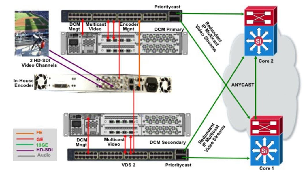
In this example (for RP implementations):
■![]() An MPEG-4 encoder for an in-house feed is shown.
An MPEG-4 encoder for an in-house feed is shown.
■![]() The outputs from the encoder are connected to both MPEG Multiplexers.
The outputs from the encoder are connected to both MPEG Multiplexers.
■![]() Each MPEG Multiplexer has GbE connections to the corresponding video distribution switch.
Each MPEG Multiplexer has GbE connections to the corresponding video distribution switch.
■![]() Each video distribution switch has a 10 GbE connection to both core switches.
Each video distribution switch has a 10 GbE connection to both core switches.
■![]() A 1:1 active/active Prioritycast model is used between the video distribution switches and the core MPEG Multiplexers.
A 1:1 active/active Prioritycast model is used between the video distribution switches and the core MPEG Multiplexers.
■![]() All (*,G) pairs are sourced from the Primary source on MPEG Multiplexer1.
All (*,G) pairs are sourced from the Primary source on MPEG Multiplexer1.
■![]() The VDS2 ports connected to the MPEG Multiplexer2 will be activated only if there is a failure with the primary MPEG Multiplexer1 or VDS1.
The VDS2 ports connected to the MPEG Multiplexer2 will be activated only if there is a failure with the primary MPEG Multiplexer1 or VDS1.
■![]() Upon the failure of MPEG Multiplexer1 or VDS1, the subnet will no longer be available, and the network will converge on MPEG Multiplexer2.
Upon the failure of MPEG Multiplexer1 or VDS1, the subnet will no longer be available, and the network will converge on MPEG Multiplexer2.
■![]() In the core switches, unicast route is used for route convergence towards the Prioritycast RP.
In the core switches, unicast route is used for route convergence towards the Prioritycast RP.
Note: The above is an example and in some encoding cases, like when using the low-latency Harmonic CP9000 encoder, the encoder will connect directly to the VDS switches.
Encrypted Video Streams
Video streams can be encrypted in AES-128 format. Settings in the Cisco Vision Dynamic Signage Director allows to configure that as a global setting for the DMPs.
When a video feed is not encrypted, the decryption key passed to the DMPs will simply ignore it.
Video Encoding
Video encoders are commonly used to take uncompressed source in-house video and convert it to the proper IPTV format and encapsulate in multicast frames.
Harmonic CP9000 Video Encoder
The Harmonic CP9000 is a HD ultra-low latency streaming encoder from Harmonic. After configuration per Harmonic’s configuration guide, the output can be readily placed into the VDS as source multicast streams. Here are some of the highlights:
■![]() AVC and HEVC (H.264/H.265) codecs
AVC and HEVC (H.264/H.265) codecs
■![]() Low latency depending on network performance from 266 ms – 566 ms end to end.
Low latency depending on network performance from 266 ms – 566 ms end to end.
Note: Output from this encoder is IPTV and should not be passed through a MPEG Multiplexer since this will unnecessarily add latency to the stream. This encoder features dual GbE interfaces which should be connected to the VDS switches directly.
Service Provider Demarcation Switch Examples
The demarcation (demarc) switch is used with clear and encrypted IP feeds from a service provider. A few examples of the typical setup, including one used with DirecTV bundle will be shown here. Other configurations are possible.
Demarc Switch: Clear IP Feeds Connections
Figure 6 Demarc Connections—Clear IP Feeds

On ingress, each demarcation switch is connected to the source via GbE going into a VLAN.
The service provider typically floods multicast to the demarc switches. If the SP does not provide the demarc, then the feeds will terminate at the VDS1/2 directly.
On egress, each demarcation switch sends an identical copy of the feed to each of the video distribution switches via GbE.
Typically, there is L2 on the demarc, it’s all VLAN/Trunk with IGMP snooping disabled on demarc for content VLANs.
If MPEG Multiplexers (shown as DCMs in Figure 6) are not used, then the provider’s L3 addressing must be known by the global/VRF routing table.
DirecTV / Technicolor Connections (North America)
The Technicolor COM3000 can accommodate up to six COM51 blades in the COM400 chassis, with each blade able to tune up to 23 high-definition channels as well as tuning DirecTV UHD content.

Typically no demarc switch is used in this configuration unless provided by the service provider, so the COM400 will terminate directly to the VDS1/2. Here’s a link to the datasheet.
If MPEG Multiplexer (Figure 7 1 as DCM) is used, then this and any SP feeds should be terminated on the multiplexer via L2 VLAN without IGMP snooping.
Video Monitoring
Our recommendation is to use a MPEG Analyzer for comprehensive monitoring.
For basic troubleshooting, sometimes a DMP off the demarcation switch or VDS switch for troubleshooting clear IP video sources at the service provider’s drop-off point can be used. Ensure that POE and IP Services license are supported on primary demarcation or VDS switch to use DMP for troubleshooting. For baseline design or cost-sensitive venues with redundancy, plan connections and configurations to go on VDS.
In addition, a HD-SDI TV that supports input, audio and closed caption can be used to monitor video feed.
Figure 8 Monitoring incoming HD-SDI feeds via HD-SDI TV

 Feedback