Configure Authentication on AireOS Wireless LAN Controllers
Available Languages
Download Options
Bias-Free Language
The documentation set for this product strives to use bias-free language. For the purposes of this documentation set, bias-free is defined as language that does not imply discrimination based on age, disability, gender, racial identity, ethnic identity, sexual orientation, socioeconomic status, and intersectionality. Exceptions may be present in the documentation due to language that is hardcoded in the user interfaces of the product software, language used based on RFP documentation, or language that is used by a referenced third-party product. Learn more about how Cisco is using Inclusive Language.
Contents
Introduction
This document describes how to configure different types of layer authentication methods on Wireless LAN Controllers (WLCs).
Prerequisites
Requirements
Ensure that you meet these requirements before you attempt this configuration:
-
Knowledge of the configuration of Lightweight Access Points (LAPs) and Cisco WLCs
-
Knowledge of 802.11i security standards
Components Used
The information in this document is based on these software and hardware versions:
-
Cisco 4400 WLC that runs firmware release 6.0.182.0
-
Cisco 1000 Series LAPs
-
Cisco 802.11a/b/g Wireless Client Adapter that runs firmware release 2.6
-
Cisco Secure ACS server version 3.2
The information in this document was created from the devices in a specific lab environment. All of the devices used in this document started with a cleared (default) configuration. If your network is live, ensure that you understand the potential impact of any command.
Conventions
Refer to Cisco Technical Tips Conventions for more information on document conventions.
Authentication on WLCs
The Cisco Unified Wireless Network (UWN) security solution bundles potentially complicated Layer 1, Layer 2, and Layer 3 802.11 Access Point (AP) security components into a simple policy manager that customizes system-wide security policies on a per-wireless LAN (WLAN) basis. The Cisco UWN security solution provides simple, unified, and systematic security management tools.
These security mechanisms can be implemented on WLCs.
Layer 1 Solutions
Restrict client access based on the number of consecutive failed attempts.
Layer 2 Solutions
None Authentication —When this option is selected from the Layer 2 Security drop-down list, No Layer 2 authentication is performed on the WLAN. This is the same as the open authentication of the 802.11 standard.
Static WEP —With Static Wired Equivalent Privacy (WEP), all APs and client radio NICs on a particular WLAN must use the same encryption key. Each sending station encrypts the body of each frame with a WEP key before transmission, and the receiving station decrypts it using an identical key upon reception.
802.1x—Configures the WLAN to use the 802.1x based authentication. The use of IEEE 802.1X offers an effective framework in order to authenticate and control user traffic to a protected network, as well as dynamically vary encryption keys. 802.1X ties a protocol called Extensible Authentication Protocol (EAP) to both the wired and WLAN media and supports multiple authentication methods.
Static WEP + 802.1x—This Layer 2 security setting enables both 802.1x and Static WEP. Clients can either use Static WEP or 802.1x authentication in order to connect to the network.
Wi-Fi Protected Access (WPA)—WPA or WPA1 and WPA2 are standard-based security solutions from the Wi-Fi Alliance that provide data protection and access control for WLAN systems. WPA1 is compatible with the IEEE 802.11i standard but was implemented before the standard ratification. WPA2 is the Wi-Fi Alliance implementation of the ratified IEEE 802.11i standard.
By default, WPA1 uses Temporal Key Integrity Protocol (TKIP) and message integrity check (MIC) for data protection. WPA2 uses the stronger Advanced Encryption Standard encryption algorithm using Counter Mode with Cipher Block Chaining Message Authentication Code Protocol (AES-CCMP). Both WPA1 and WPA2 use 802.1X for authenticated key management by default. However, these options are also available: PSK, CCKM, and CCKM+802.1x. If you select CCKM, Cisco only allows clients which support CCKM. If you select CCKM+802.1x, Cisco allows non-CCKM clients also.
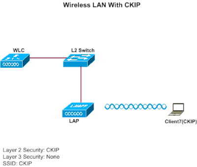
CKIP—Cisco Key Integrity Protocol (CKIP) is a Cisco-proprietary security protocol for encrypting 802.11 media. CKIP improves 802.11 security in infrastructure mode using key permutation, MIC, and message sequence number. Software release 4.0 supports CKIP with static key. For this feature to operate correctly, you must enable Aironet information elements (IEs) for the WLAN. The CKIP settings specified in a WLAN are mandatory for any client that attempts to associate. If the WLAN is configured for both CKIP key permutation and MMH MIC, the client must support both. If the WLAN is configured for only one of these features, the client must support only this CKIP feature. WLCs only support static CKIP (like static WEP). WLCs do not support CKIP with 802.1x (dynamic CKIP).
Layer 3 Solutions
None—When this option is selected from the Layer 3 security drop-down list, no Layer 3 authentication is performed on the WLAN.

Note: The configuration example for No Layer 3 authentication and No Layer 2 authentication is explained in the None Authentication section.
Web Policy (Web Authentication and Web Passthrough)—Web authentication is typically used by customers who want to deploy a guest-access network. In a guest-access network, there is initial username and password authentication, but security is not required for the subsequent traffic. Typical deployments can include "hot spot" locations, such as T-Mobile or Starbucks.
Web authentication for the Cisco WLC is done locally. You create an interface and then associate a WLAN/service set identifier (SSID) with that interface.
Web authentication provides simple authentication without a supplicant or client. Keep in mind that web authentication does not provide data encryption. Web authentication is typically used as simple guest access for either a "hot spot" or campus atmosphere where the only concern is the connectivity.
Web passthrough is a solution through which wireless users are redirected to an acceptable usage policy page without having to authenticate when they connect to the Internet. This redirection is taken care of by the WLC itself. The only requirement is to configure the WLC for web passthrough, which is basically web authentication without having to enter any credentials.
VPN Passthrough—VPN Passthrough is a feature which allows a client to establish a tunnel only with a specific VPN server. Therefore, if you need to securely access the configured VPN server as well as another VPN server or the Internet, this is not possible with VPN Passthrough enabled on the controller.
In the next sections, configuration examples are provided for each of the authentication mechanisms.
Configuration Examples
Before you configure the WLANs and the authentication types, you must configure the WLC for basic operation and register the LAPs to the WLC. This document assumes that the WLC is configured for basic operation and that the LAPs are registered to the WLC. If you are a new user trying to setup the WLC for basic operation with LAPs, refer to Lightweight AP (LAP) Registration to a Wireless LAN Controller (WLC).
Layer 1 Security Solutions
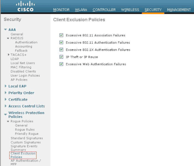
Wireless clients can be restricted access based on the number of consecutive failed attempts to access the WLAN network. Client exclusion occurs in these conditions by default. These values cannot be changed.
-
Consecutive 802.11 Authentication Failure (5 consecutive times, 6th try is excluded)
-
Consecutive 802.11 Association Failures (5 consecutive times, 6th try is excluded)
-
Consecutive 802.1x Authentication Failures (3 consecutive times, 4th try is excluded)
-
External Policy Server Failure
-
Attempt to use IP address already assigned to another device (IP Theft or IP Reuse)
-
Consecutive Web Authentication (3 consecutive times, 4th try is excluded)
In order to locate the Client Exclusion Policies, click Security in the top menu, and then choose Wireless Protection Policies > Client Exclusion Policies the navigation on the left side of the page.
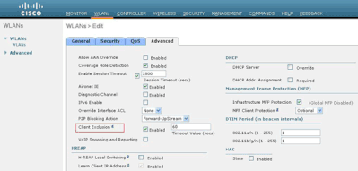
The exclusion timer can be configured. Exclusion options can be enabled or disabled per controller. The exclusion timer can be enabled or disabled per WLAN.
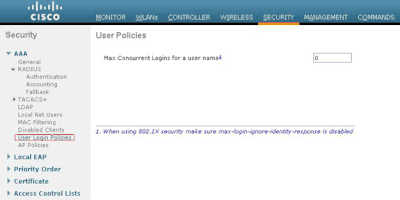
The Maximum Number of Concurrent Logins for a single user name by default is 0. You can enter any value between 0 and 8. This parameter can be set at SECURITY > AAA > User Login Policies and allows you to specify the maximum number of concurrent logins for a single client name, between one and eight, or 0 = unlimited. Here is an example:
Layer 2 Security Solutions
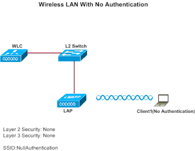
None Authentication
This example shows a WLAN configured without authentication.
Note: This example also works for No Layer 3 authentication.
Configure WLC for No Authentication
Complete these steps in order to configure the WLC for this setup:
-
Click WLANs from the controller GUI in order to create a WLAN.
The WLANs window appears. This window lists the WLANs configured on the controller.
-
Click Go in order to configure a new WLAN.
-
Enter the parameters for the WLAN. This example shows configuration for this WLAN.
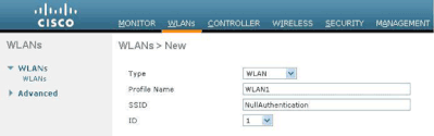
-
Click Apply.
-
In the WLAN > Edit window, define the parameters specific to the WLAN.
-
Click the Security tab, and choose None for Layer 2 and Layer 3 security.
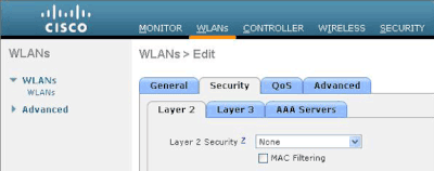
Note: For a WLAN to become active, the status must be enabled. To enable it, check the Status check box under the General tab.
This enables No authentication for this WLAN.
-
Choose other parameters based on your design requirements. This example uses the default values.
-
Click Apply.
Configure Wireless Client for No Authentication
Complete these steps in order to configure the Wireless LAN client for this setup:
Note: This document uses an Aironet 802.11a/b/g Client Adapter that runs firmware 3.5 and explains the configuration of the client adapter with ADU version 3.5.
-
In order to create a new profile, click the Profile Management tab on the ADU.
-
Click New.
-
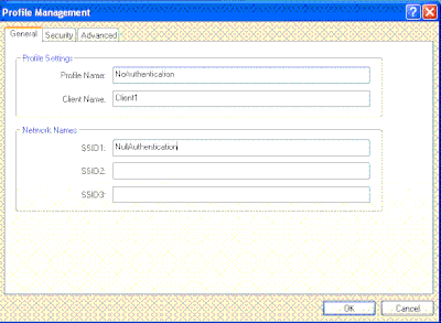
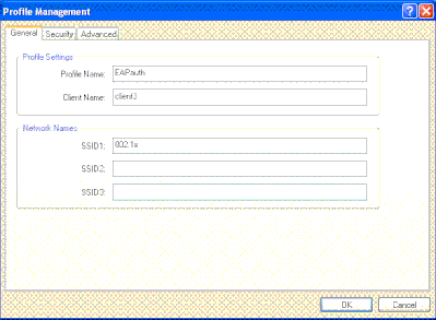
When the Profile Management (General) window displays, complete these steps in order to set the profile name, client name, and SSID:
-
Enter the name of the profile in the Profile Name field.
This example uses NoAuthentication as the profile name.
-
Enter the name of the client in the Client Name field.
The client name is used to identify the wireless client in the WLAN network. This configuration uses Client 1 for the client name.
-
Under Network Names, enter the SSID that is to be used for this profile.
The SSID is the same as the SSID that you configured on the WLC. The SSID in this example is NullAuthentication .
-
-
Click the Security tab.
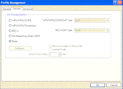
-
Click the None radio button under Set Security Options, and then click OK .
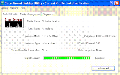
When the SSID is activated, the wireless client connects to the WLAN without any authentication.
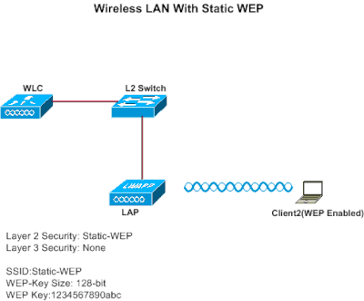
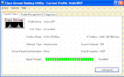
Static WEP
This example shows a WLAN configured with static WEP.
Configure WLC for Static WEP
Complete these steps in order to configure the WLC for this setup:
-
Click WLANs from the controller GUI in order to create a WLAN.
The WLANs window appears. This window lists the WLANs configured on the controller.
-
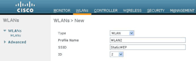
Click New in order to configure a new WLAN.
-
Enter the WLAN ID and WLAN SSID.
In this example, the WLAN is named StaticWEP and the WLAN ID is 2.
-
Click Apply .
-
In the WLAN > Edit window, define the parameters specific to the WLAN.
-
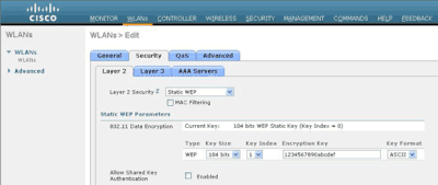
From the Layer 2 drop-down list, choose Static WEP.
This enables Static WEP for this WLAN.
-
Under Static WEP parameters, choose the WEP key size and key index, and enter the static WEP encryption key.
The key size can be either 40 bits or 104 bits. The key index can be between 1 and 4. One unique WEP Key Index can be applied to each WLAN. Because there are only four WEP Key Indexes, only four WLANs can be configured for Static WEP Layer 2 encryption. In this example, the 104 bit WEP is used and the WEP key used is 1234567890abcdef.
-
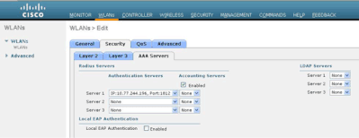
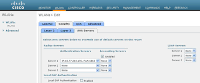
Check if the Radius server is configured for authentication. The Radius server can be configured on the Security tab located at AAA > Radius > Authentication. Once configured, the Radius server must be assigned to the WLAN for authentication. Go to WLANs > Security > AAA Servers in order to assign the Radius server to the WLAN for authentication.
In this example, 10.77.244.196 is the Radius server.
-
-
Choose other parameters based on your design requirements.
This example uses the default values.
-
Click Apply.
Note: WEP is always represented in hexadecimal (hex). When you enter the WEP key in ASCII, the ASCII WEP string is converted to hex, which is used to encrypt the packet. There is no standard method that vendors perform to convert hex to ASCII, as some can do padding while others cannot. Therefore, for maximum inter-vendor compatibility, use hex for your WEP keys.
Note: If you want to enable Shared Key Authentication for the WLAN, check the Allow Shared-Key Authentication check box under Static WEP Parameters. This way, if the client is also configured for Shared Key Authentication, Shared Key Authentication followed by WEP encryption of packets can take place in the WLAN.
Configure Wireless Client for Static WEP
Complete these steps in order to configure the Wireless LAN Client for this setup:
-
In order to create a new profile, click the Profile Management tab on the ADU.
-
Click New.
-
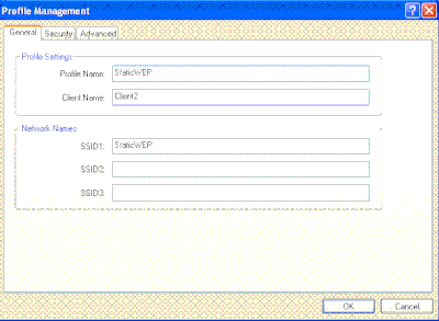
When the Profile Management (General) window displays, complete these steps in order to set the profile name, client name, and SSID:
-
Enter the name of the profile in the Profile Name field.
This example uses StaticWEP as the profile name.
-
Enter the name of the client in the Client Name field.
The client name is used to identify the wireless client in the WLAN network. This configuration uses Client 2 for the client name.
-
Under Network Names, enter the SSID that is to be used for this profile.
The SSID is the same as the SSID that you configured on the WLC. The SSID in this example is StaticWEP.
-
-
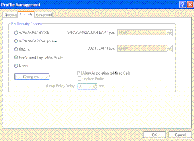
Click the Security tab.
-
Choose Pre-Shared Key (Static WEP) under Set Security Options.
-
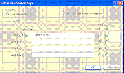
Click Configure , and define the WEP key size and the WEP key.
This must match with the WEP key configured on the WLC for this WLAN.
-
ClickApply.
When the SSID is activated, the wireless client connects to the WLAN and the packets are encrypted using the static WEP key.
802.1x Authentication
This example shows a WLAN configured with 802.1x authentication.
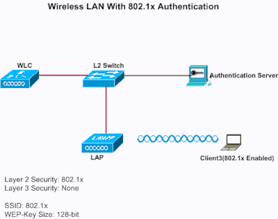
Configure WLC for 802.1x Authentication
Complete these steps in order to configure the WLC for this setup:
-
Click WLANs from the controller GUI in order to create a WLAN.
The WLANs window appears. This window lists the WLANs configured on the controller.
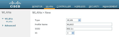
-
Click New in order to configure a new WLAN.
In this example, the WLAN is named 802.1x , and the WLAN ID is 3. A profile name must also be added.
-
Click Apply.
-
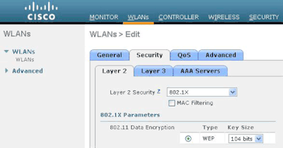
In the WLAN > Edit window, define the parameters specific to the WLAN.
-
From the Layer 2 drop-down list, choose 802.1x .
Note: Only WEP encryption is available with 802.1x. Choose either 40 bits or 104 bits for encryption, and make sure Layer 3 security is set to None.
This enables 802.1x authentication for this WLAN.
-
Under RADIUS server parameters, select the RADIUS server that can be used to authenticate the client credentials.
-
Choose other parameters based on your design requirements.
This example uses the default values.
-
-
Click Apply.
Notes
-
If you choose 802.1x for Layer 2 security, CCKM cannot be used.
-
If you choose WPA 1 or WPA 2 for Layer 2 security, these options appear under Auth Key Management:
-
802.1x+CCKM —If you choose this option, both CCKM or non-CCKM clients are supported (CCKM optional).
-
802.1x—If you choose this option, only 802.1x clients are supported.
-
CCKM—If you choose this option, only CCKM clients are supported, where clients are directed to an external server for authentication.
-
PSK—If you choose this option, a pre-shared key is used for the WLC and client. Also, all standards are set to be used to before pre-standards; for example, WPA/WPA2 takes precedent over CCKM when used simultaneously.
-
The type of EAP authentication used to validate the clients is dependent on the EAP type configured on the RADIUS server and the wireless clients. Once 802.1x is enabled on the WLC, the WLC allows all types of EAP packets to flow between the LAP, the wireless client and the RADIUS server.
These documents provide configuration examples on some of the EAP authentication types:
-
Configure Wireless Client for 802.1x Authentication
Complete these steps in order to configure the Wireless LAN Client for this setup:
-
In order to create a new profile, click the Profile Management tab on the ADU.
-
Click New.
-
When the Profile Management (General) window displays, complete these steps in order to set the profile name, client name, and SSID:
-
Enter the name of the profile in the Profile Name field.
This example uses EAPAuth as the profile name.
-
Enter the name of the client in the Client Name field.
The client name is used to identify the wireless client in the WLAN network. This configuration uses Client 3 for the client name.
-
Under Network Names, enter the SSID that is to be used for this profile.
The SSID is the same as the SSID that you configured on the WLC. The SSID in this example is 802.1x .
-
-
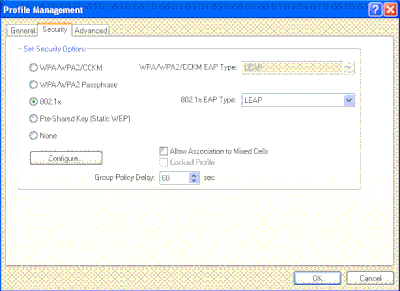
Click the Security< /strong>tab.
-
Click the 802.1x radio button.
-
From the 802.1x EAP Type drop-down list, choose the EAP type used.
-
Click Configure in order to configure parameters specific to the selected EAP type.

-
Click Apply.
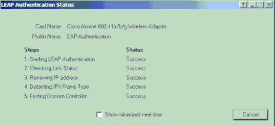
When the SSID is activated, the wireless client connects to the WLAN using 802.1x authentication. Dynamic WEP keys are used for the sessions.
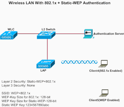
Static WEP + 802.1x Authentication
This example shows a WLAN configured with static WEP + 802.1x authentication.
Complete these steps in order to configure the WLC for this setup:
-
Click WLANs from the controller GUI in order to create a WLAN.
The WLANs window appears. This window lists the WLANs configured on the controller.
-
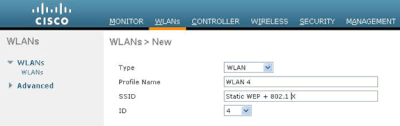
Click New in order to configure a new WLAN.
-
Enter the WLAN ID and WLAN SSID.
In this example, the WLAN is named WEP+802.1x , and the WLAN ID is 4 .
-
Click Apply.
-
In the WLAN > Edit window, define the parameters specific to the WLAN.
-
From the Layer 2 drop-down list, choose Static-WEP+802.1x.
This enables both Static WEP and 802.1x authentication for this WLAN.
-
Under RADIUS server parameters, select the RADIUS server that can be used to authenticate the client credentials using 802.1x, and configure the RADIUS server as shown in the previous example.
-
Under Static WEP parameters, select the WEP key size and key index, and enter the static WEP encryption key as shown in the previous image.
-
Choose other parameters based on your design requirements.
This example uses the default values.
-
Configure the Wireless Client for Static WEP and 802.1x
See the Configure Wireless Client for 802.1x Authentication and Configure Wireless Client for Static WEP sections for information on how to configure the wireless client.
Once the client profiles are created, clients that are configured for static WEP associate with the LAP. Use the SSID WEP+802.1x in order to connect to the network.
Similarly, wireless clients which are configured to use 802.1x authentication are authenticated using EAP and access the network with the same SSID WEP+802.1x.
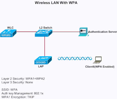
Wi-Fi Protected Access
This example shows a WLAN which is configured with WPA with 802.1x.
Configure the WLC for WP
Complete these steps in order to configure the WLC for this setup:
-
Click WLANs from the controller GUI in order to create a WLAN.
The WLANs window appears. This window lists the WLANs configured on the controller.
-
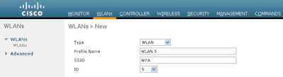
Click Go in order to configure a new WLAN.
Choose the type and profile name. In this example, the WLAN is named WPA , and the WLAN ID is 5 .
-
Click Apply .
-
In the WLAN > Edit window, define the parameters specific to the WLAN.
-
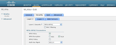
Click the Security tab, click the Layer 2 tab, and choose WPA1+WPA2 from the Layer 2 Security drop-down list.
-
Under WPA1+WPA2 Parameters, check the WPA1 Policy check box in order to enable WPA1, check the WPA2 Policy check box in order to enable WPA2, or check both check boxes in order to enable both WPA1 and WPA2.
The default value is disabled for both WPA1 and WPA2. If you leave both WPA1 and WPA2 disabled, the access points advertise in their beacons and probe response information elements only for the authentication key management method you choose.
-
Check the AES check box in order to enable AES data encryption or the TKIP check box in order to enable TKIP data encryption for WPA1, WPA2, or both.
The default values are TKIP for WPA1 and AES for WPA2.
-
Choose one of these key management methods from the Auth Key Mgmt drop-down list:
-
802.1X—If you choose this option, only 802.1x clients are supported.
-
CCKM—If you choose this option, only CCKM clients are supported, where clients are directed to an external server for authentication.
-
PSK—If you choose this option, a pre-shared key is used for the WLC and client. Also, all standards are set to be used to before pre-standards; for example, WPA/WPA2 takes precedent over CCKM when used simultaneously.
-
802.1X+CCKM—If you choose this option, both CCKM or non-CCKM clients are supported (CCKM optional).
This example uses 802.1x.
Note: If you choose PSK, choose ascii or hex from the PSK Format drop-down list, and then enter a pre-shared key in the blank field. WPA pre-shared keys must contain 8 to 63 ASCII text characters or 64 hex characters.
-
-
-
Click Apply in order to apply your changes.
Configure the Wireless Client for WPA
Complete these steps in order to configure the Wireless LAN client for this setup:
-
In the Profile Management window on the ADU, click New in order to create a new profile.
-
Click the General tab, and enter the profile name and the SSID that the client adapter can use.
In this example, the profile name and the SSID are WPA . The SSID must match the SSID that you configured on the WLC for WPA.
-
On the Security tab, click the WPA/WPA2/CCKM radio button, and choose the appropriate EAP type from the WPA/WPA2/CCKM EAP Type drop-down list. This step enables WPA.

-
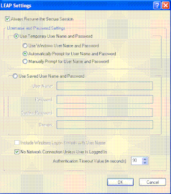
Click Configure in order to define the EAP settings specific to the type of EAP selected.
-
ClickOK.
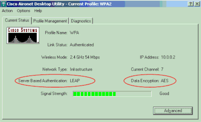
Note: When this profile is activated, the client is authenticated using 802.1x and when authentication is successful, the client connects to the WLAN. Check the ADU Current Status in order to verify that the client uses TKIP encryption (default encryption used by WPA1) and EAP authentication.
CKIP
This example shows a WLAN configured with CKIP.
Configure the WLC for CKIP
Complete these steps in order to configure the WLC for this setup:
-
Click WLANs from the controller GUI in order to create a WLAN.
The WLANs window appears. This window lists the WLANs configured on the controller.
-
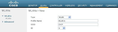
Click New in order to configure a new WLAN.
Choose the type and profile name. In this example, the WLAN is named CKIP and the WLAN ID is 6 .
-
In the WLAN > Edit window, define the parameters specific to the WLAN.
-
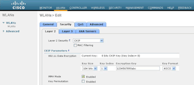
From the Layer 2 drop-down list, choose CKIP.
This step enables CKIP for this WLAN.
-
Under the CKIP parameters, select the key size and key index, and enter the static encryption key.
The key size can be either 40 bits, 104 bits, or 128 bits. The key index can be between 1 and 4. One unique WEP key index can be applied to each WLAN. Because there are only four WEP key indexes, only four WLANs can be configured for static WEP Layer 2 encryption.
-
For CKIP, choose the MMH Mode option, or the Key Permutation option, or both.
Note: Either one of these parameters or both must be selected for CKIP to work as expected. If these parameters are not selected, the WLAN stays in the disabled state.
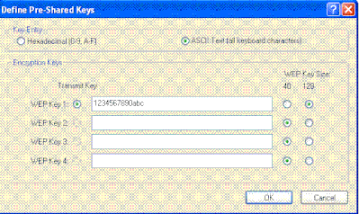
In this example, 104 bit key is used, and the key is 1234567890abc.
-
-
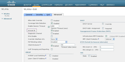
Choose other parameters based on your design requirements.
This example uses the default values.
-
ClickApply.
Note: CKIP is functional on the 1100, 1130, and 1200 APs, but not AP 1000. Aironet IE needs to be enabled for this feature to work. CKIP expands the encryption keys to 16 bytes.
Configure the Wireless Client for CKIP
Complete these steps in order to configure the Wireless LAN Client for this setup:
-
In order to create a new profile, click the Profile Management tab on the ADU, and then click New.
-
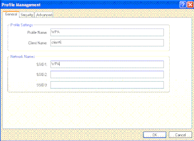
When the Profile Management (General) window displays, complete these steps in order to set the profile name, client name, and SSID:
-
Enter the name of the profile in the Profile Name field.
This example uses CKIP as the profile name.
-
Enter the name of the client in the Client Name field.
The client name is used to identify the wireless client in the WLAN network. This configuration uses Client6 for the client name.
-
Under Network Names, enter the SSID that is to be used for this Profile.
The SSID is the same as the SSID that you configured on the WLC. The SSID in this example is CKIP .

-
-
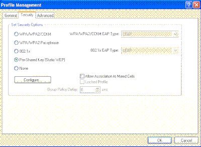
Click the Security tab.
-
Choose Pre-Shared Key (Static WEP) under Set Security Options, click Configure , and define the WEP key size and the WEP key.
These values must match with the WEP key configured on the WLC for this WLAN.
-
Click OK .
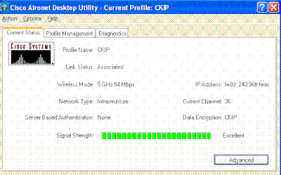
When the SSID is activated, the wireless client negotiates with the LAP and WLC to use CKIP for encryption the packets.
Layer 3 Security Solutions
Web Policy (Web Authentication and Web Passthrough)
Refer to Wireless LAN Controller Web Authentication Configuration Example for information on how to enable web authentication in a WLAN network.
Refer to External Web Authentication with Wireless LAN Controllers Configuration Example for information on how to configure external web authentication and web passthrough authentication in a WLAN.
Refer toWireless LAN Controller Web Passthrough Configuration Example for more information on how to enable web passthrough in a WLAN network.
The Splash Page mechanism is a Layer 3 security mechanism introduced in WLC Version 5.0 used for client authentication. Refer to Wireless LAN Controller Splash Page Redirect Configuration Example for more information.
VPN Passthrough
Refer to Client VPN over Wireless LAN with WLC Configuration Example for information on how to configure VPN passthrough in a WLAN.
Troubleshoot
Troubleshooting Commands
You can use these debug commands to troubleshoot your configuration.
Debugs for Web Authentication:
-
debug mac addr<client-MAC-address xx:xx:xx:xx:xx:xx>—Configures MAC address debugging for the client.
-
debug aaa all enable—Configures debugging of all AAA messages.
-
debug pem state enable— Configures debug of policy manager State Machine
-
debug pem events enable—Configures debug of policy manager events.
-
debug dhcp message enable—Use this command in order to display debugging information about the Dynamic Host Configuration Protocol (DHCP) client activities and to monitor the status of DHCP packets.
-
debug dhcp packet enable—Use this command in order to display DHCP packet level information.
-
debug pm ssh-appgw enable—Configures debug of application gateways.
-
debug pm ssh-tcp enable—Configures debug of policy manager tcp handling
Debugs for WEP : No debug for WEP because it is performed at the AP, turn ondebug dot11 all enable.
Debugs for 802.1X/WPA/RSN/PMK caching:
-
debug mac addr <client-MAC-address xx:xx:xx:xx:xx:xx>—Configures MAC address debugging for the client.
-
debug dot1x all enable—Use this command in order to display 802.1X debugging information.
-
debug dot11 all enable—Use this command in order to enable debugging of radio functions.
-
debug pem events enable—Configures debug of policy manager events.
-
debug pem state enable—Configures debug of policy manager State Machine.
-
debug dhcp message enable—Use this command in order to display debugging information about the Dynamic Host Configuration Protocol (DHCP) client activities and to monitor the status of DHCP packets.
-
debug dhcp packet enable—Use this command in order to display DHCP packet level information.
-
debug mobility handoff enable (for intra-switch roaming)—Configures debug of Mobility packets.
-
show client detail <mac>—Displays detailed information for a client by mac address. Check the WLAN and RADIUS session timeout configuration.
Related Information
Revision History
| Revision | Publish Date | Comments |
|---|---|---|
2.0 |
22-Sep-2023 |
Recertification |
1.0 |
09-Jul-2010 |
Initial Release |
Contributed by Cisco Engineers
 Feedback
Contact Cisco
- Open a Support Case

- (Requires a Cisco Service Contract)