Introduction
This document provides a sample configuration for Network Time Protocol (NTP) on Cisco Nexus 7000 Series Switches.
Prerequisites
Requirements
Ensure that you meet these requirements before you attempt this configuration:
Components Used
The information in this document is based on the Nexus 7000 Series Switch.
The information in this document was created from the devices in a specific lab environment. All of the devices used in this document started with a cleared (default) configuration. If your network is live, make sure that you understand the potential impact of any command.
Conventions
Refer to the for more information on document conventions.
Background Information
The Network Time Protocol (NTP) synchronizes the time of day among a set of distributed time servers and clients so that you can correlate events when you receive system logs and other time-specific events from multiple network devices. NTP uses the User Datagram Protocol (UDP) as its transport protocol. All NTP communications use Coordinated Universal Time (UTC).
Cisco recommends that you use the public NTP servers available on the Internet. If the network is isolated from the Internet, Cisco NX-OS allows you to configure the time as though it were already synchronized through the NTP server.
Configure
In this section, you are presented with the information to configure the NTP features described in this document.
In order to configure NTP on a Nexus 7000 switch, you must have connectivity to at least one server that is running NTP.
NTP must be configured in the default virtual device context (VDC). It cannot be configured in any other VDC.
If you configure NTP in a VRF, ensure the NTP server and peers can reach each other through the configured VRFs.
Network Diagram
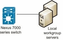
This document uses this network setup:

Configurations
This document uses these configurations:
| Nexus 7000 Switch |
Nexus_7000#configure terminal


!--- Form an association with a server. Use the prefer keyword to make this
!--- server as preferred NTP server.

Nexus_7000(config)#ntp server 129.6.15.28 prefer
Nexus_7000(config)#ntp server 129.6.15.29

!--- Configure the source interface for all NTP packets.

Nexus_7000(config)#ntp source-interface  vlan1

!--- Configure the device as an authoritative NTP server.

Nexus_7000(config)#ntp master 1

Nexus_7000(config)#interface vlan1
Nexus_7000(config-if)#no shutdown
Nexus_7000(config-if)#no ip redirects
Nexus_7000(config-if)#ip address 172.20.100.34/24
Nexus_7000(config-if)#ip address 172.20.100.30/24 secondary


!--- Save the configurations in the device.

Nexus_7000(config)#copy running-config startup-config
Nexus_7000(config)#exit
|
Verify
Use this section to confirm that your configuration works properly.
The Cisco CLI Analyzer (registered customers only) supports certain show commands. Use the Cisco CLI Analyzer to view an analysis of show command output.
Use the show ntp peers command in order to display all the NTP peers.
For example:
Nexus_7000#show ntp peers
--------------------------------------------------
  Peer IP Address               Serv/Peer
--------------------------------------------------
  127.127.1.0                   Server (configured)
  129.6.15.28                   Server (configured)
  129.6.15.29                   Server (configured)
Use the show ntp peer-status command in order to display the status for all NTP servers and peers.
For example:
Nexus_7000#show ntp peer-status
Total peers : 3
* - selected for sync, + -  peer mode(active),
- - peer mode(passive), = - polled in client mode
    remote               local                 st   poll   reach delay   vrf
-------------------------------------------------------------------------------
=127.127.1.0            172.20.100.34           1   64       0   0.00000
*129.6.15.28            172.20.100.34           1   64     377   0.03938 default
=129.6.15.29            172.20.100.34           1   64     377   0.01804 default
Use the show ntp logging-status command in order to display the NTP logging status.
Troubleshoot
There is currently no specific troubleshooting information available for this configuration.
Related Information
