Configuring IDS TCP Reset Using VMS IDS MC
Available Languages
Contents
Introduction
The document provides a sample configuration of the Cisco Intrusion Detection System (IDS) via the VPN/Security Management Solution (VMS), IDS Management Console (IDS MC). In this case, TCP Reset from the IDS Sensor to a Cisco router is configured.
Prerequisites
Requirements
Ensure that you meet these requirements before you attempt this configuration:
-
The Sensor is installed and configured for sensing necessary traffic.
-
The sniffing interface is spanned to the router outside interface.
Components Used
The information in this document is based on these software and hardware versions:
-
VMS 2.2 with IDS MC and Security Monitor 1.2.3
-
Cisco IDS Sensor 4.1.3S(63)
-
Cisco Router that runs Cisco IOS® Software Release 12.3.5
The information in this document was created from the devices in a specific lab environment. All of the devices used in this document started with a cleared (default) configuration. If your network is live, make sure that you understand the potential impact of any command.
Conventions
Refer to Cisco Technical Tips Conventions for more information on document conventions.
Configure
In this section, you are presented with the information to configure the features described in this document.
Note: Use the Command Lookup Tool (registered customers only) to obtain more information on the commands used in this section.
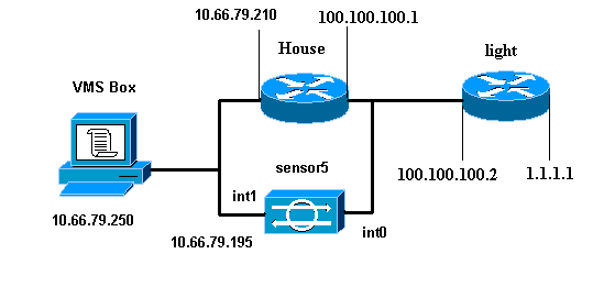
Network Diagram
This document uses this network setup:
Configurations
This document uses these configurations.
| Router Light |
|---|
Current configuration : 906 bytes ! version 12.3 service timestamps debug uptime service timestamps log uptime no service password-encryption ! hostname light ! enable password cisco ! username cisco password 0 cisco ip subnet-zero ! ! ! ip ssh time-out 120 ip ssh authentication-retries 3 ! call rsvp-sync ! ! ! fax interface-type modem mta receive maximum-recipients 0 ! controller E1 2/0 ! ! ! interface FastEthernet0/0 ip address 100.100.100.2 255.255.255.0 duplex auto speed auto ! interface FastEthernet0/1 ip address 1.1.1.1 255.255.255.0 duplex auto speed auto ! interface BRI4/0 no ip address shutdown ! interface BRI4/1 no ip address shutdown ! interface BRI4/2 no ip address shutdown ! interface BRI4/3 no ip address shutdown ! ip classless ip route 0.0.0.0 0.0.0.0 100.100.100.1 ip http server ip pim bidir-enable ! ! dial-peer cor custom ! ! line con 0 line 97 108 line aux 0 line vty 0 4 login ! end |
| Router House |
|---|
Building configuration... Current configuration : 797 bytes ! version 12.3 no service pad service timestamps debug datetime msec service timestamps log datetime msec no service password-encryption ! hostname House ! logging queue-limit 100 enable password cisco ! ip subnet-zero no ip domain lookup ! ! interface Ethernet0 ip address 10.66.79.210 255.255.255.224 hold-queue 100 out ! interface Ethernet1 ip address 100.100.100.1 255.255.255.0 ip classless ip route 0.0.0.0 0.0.0.0 10.66.79.193 ip route 1.1.1.0 255.255.255.0 100.100.100.2 ip http server no ip http secure-server ! ! ! line con 0 stopbits 1 line vty 0 4 password cisco login ! scheduler max-task-time 5000 end |
Initial Sensor Configuration
Note: If you have already performed the initial setup of your Sensor, proceed to the Import the Sensor into IDS MC section.
-
Console into the Sensor.
You are prompted for a username and password. If this is the first time you are consoling into the Sensor, you must login with the username cisco and password cisco.
-
You are prompted to change the password and to re-type the new password to confirm.
-
Type setup and enter the appropriate information at each prompt to set up basic parameters for your Sensor, as per this example:
sensor5#setup

    --- System Configuration Dialog ---

At any point you may enter a question mark '?' for help.
User ctrl-c to abort configuration dialog at any prompt.
Default settings are in square brackets '[]'.

Current Configuration:

networkParams
ipAddress 10.66.79.195
netmask 255.255.255.224
defaultGateway 10.66.79.193
hostname sensor5
telnetOption enabled
accessList ipAddress 10.66.79.0 netmask 255.255.255.0
exit
timeParams
summerTimeParams
active-selection none
exit
exit
service webServer
general
ports 443
exit
exit

5 Save the config:   (It might take a few minutes for the sensor
                      saving the configuration)
[0] Go to the command prompt without saving this config.
[1] Return back to the setup without saving this config.
[2] Save this configuration and exit setup.

Enter your selection[2]: 2
Import the Sensor into IDS MC
Complete these steps in order to import the Sensor into the IDS MC.
-
Browse to your Sensor. In this case, either http://10.66.79.250:1741 or https://10.66.79.250:1742.
-
Login with the appropriate username and password.
In this example, the username is admin and the password is cisco.
-
Choose VPN/Security Management Solution > Management Center and click IDS Sensors.
-
Click the Devices tab and choose Sensor Group.
-
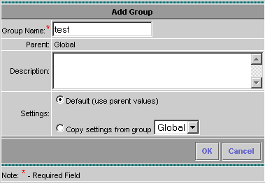
Highlight Global and click Create Subgroup.
-
Enter the Group Name and ensure that Default is chosen, then click OK in order to add the subgroup into the IDS MC.
-
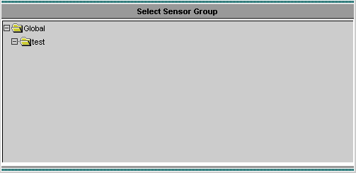
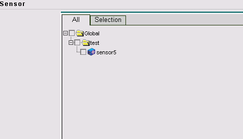
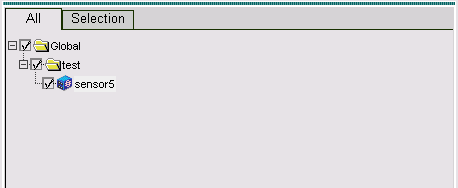
Choose Devices > Sensor, highlight the subgroup created in the previous step (in this case, test), and click Add.
-
Highlight the subgroup and click Next.
-
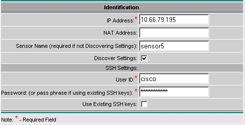
Enter the details as per this example and click Next in order to continue.
-
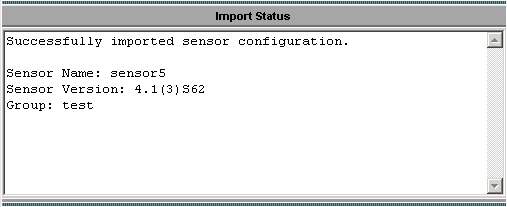
When you are presented with a message that states Successfully imported sensor configuration, click Finish in order to continue.
-
Your Sensor is imported into the IDS MC. In this case, Sensor5 is imported.


Import the Sensor into Security Monitor
Complete these steps in order to import the Sensor into Security Monitor.
-
At the VMS Server menu, choose VPN/Security Management Solution > Monitoring Center > Security Monitor.
-
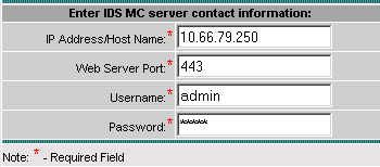
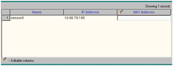
Select the Devices tab, then click Import and enter the IDS MC Server Information, as per this example.
-
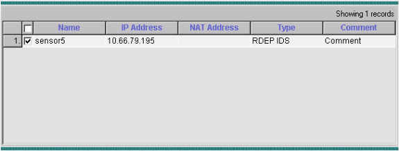
Select your Sensor (in this case, sensor5) and click Next in order to continue.
-
If needed, update the NAT address for your Sensor, then click Finish in order to continue.
-
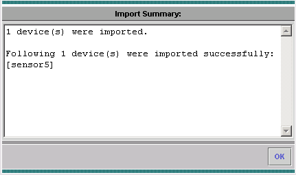
Click OK in order to finish importing the Sensor from IDS MC into Security Monitor.
-
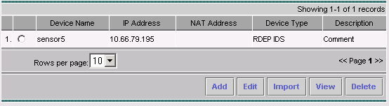
You can now see that your Sensor is successfully imported


Use IDS MC for Signature Updates
This procedure explains how to use IDS MC for signature updates.
-
Download the Network IDS Signature updates (registered customers only) and save them in the C:\PROGRA~1\CSCOpx\MDC\etc\ids\updates\ directory on your VMS Server.
-
At the VMS server console, choose VPN/Security Management Solution > Management Center > IDS Sensors.
-
Select the Configuration tab and click Updates.
-
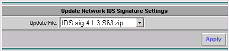
Click Update Network IDS Signatures.
-
Select the signature you want to upgrade from the drop-down menu and click Apply in order to continue.
-
Select the Sensor(s) to update and click Next in order to continue.
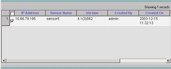
-
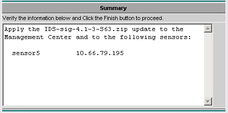
After you are prompted to apply the update to the Management Center, as well as the Sensor, click Finish in order to continue.
-
Telnet or console into the Sensor command line interface. You see information similar to this:
sensor5#
Broadcast message from root (Mon Dec 15 11:42:05 2003):
Applying update IDS-sig-4.1-3-S63.
This may take several minutes.
Please do not reboot the sensor during this update.
Broadcast message from root (Mon Dec 15 11:42:34 2003):
Update complete.
sensorApp is restarting
This may take several minutes.
-
Wait for a few minutes to allow the upgrade to complete, then enter show version in order to verify.
sensor5#show version
Application Partition:
Cisco Systems Intrusion Detection Sensor, Version 4.1(3)S63

Upgrade History:
* IDS-sig-4.1-3-S62           07:03:04 UTC Thu Dec 04 2003
   IDS-sig-4.1-3-S63.rpm.pkg   11:42:01 UTC Mon Dec 15 2003


Configure TCP Reset for IOS Router
Complete these steps in order to configure TCP reset for the IOS router.
-
Choose VPN/Security Management Solution > Management Center > IDS Sensors.
-
Select the Configuration tab, select your Sensor from Object Selector, then click Settings.
-
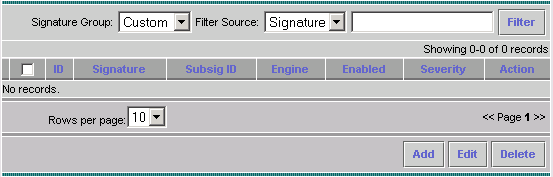
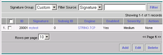
Select Signatures, click Custom, and click Add in order to add a new signature.
-
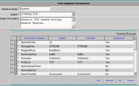
Enter the new Signature Name, then select the Engine (in this case, STRING.TCP).
-
Check the appropriate radio button in order to customize the available parameters and then click Edit.
In this example, the ServicePorts parameter is edited to change its value to 23 (for port 23). The RegexString parameter is also edited to add the value testattack. When this is complete, click OK to continue.
-
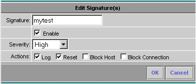
Click the name of the signature in order to edit the Signature Severity and Actions or to Enable/Disable the signature.
-
In this case, the severity is changed to High and the action Log & Reset is chosen. Click OK in order to continue.
-
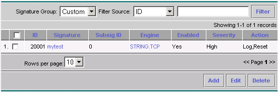
The complete signature looks similar to this:
-
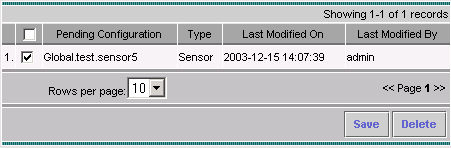
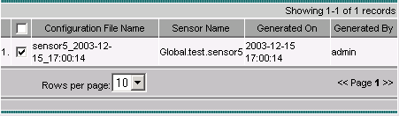
Choose Configuration > Pending, check the pending configuration to ensure it is correct, and click Save.
-
Choose Deployment > Generate, and then click Apply in order to push the configuration changes to the Sensor.
-
Choose Deployment > Deploy and click Submit.
-
Check the checkbox next to your Sensor and click Deploy.
-
Check the checkbox for the job in the queue and click Next in order to continue.
-
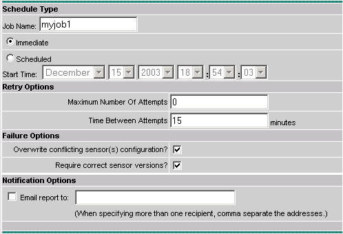
Enter the Job Name and schedule the job as Immediate, then click Finish.
-
Choose Deployment > Deploy > Pending.
Wait a few minutes until all the pending jobs have been completed. The queue should then be empty.
-
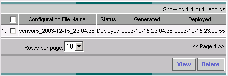
Choose Configuration > History in order to confirm the deployment.
Ensure the status of the configuration is displayed as Deployed. This means that the Sensor configuration is updated successfully.


Verify
Use this section to confirm that your configuration works properly.
Launch the Attack and TCP Reset
Launch a test attack and check the results in order to verify that the Blocking process works correctly.
-
Before the attack is launched, choose VPN/Security Management Solution > Monitoring Center > Security Monitor.
-
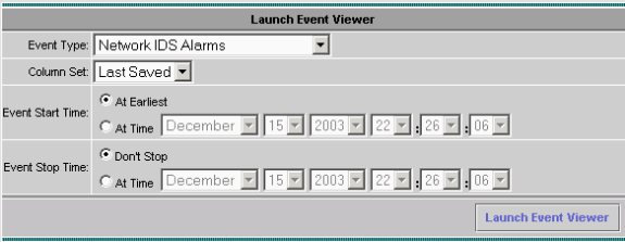
Choose Monitor from the main menu and click Events.
-
Click Launch Event Viewer.
-
Telnet from one router to the other and type testattack in order to launch the attack.
In this case, we Telnetted from the router Light to the router House. As soon as you press <space> or <enter>, after you type testattack, your Telnet session should be reset.
light#telnet 100.100.100.1
Trying 100.100.100.1 ... Open
User Access Verification
Password:
house>en
Password:
house#testattack


!--- The Telnet session is reset due to the !--- signature "testattack" being triggered.


[Connection to 100.100.100.1 lost]
-
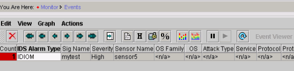
From the Event Viewer, click Query Database for new events now.
You see the alert for the previously launched attack
-
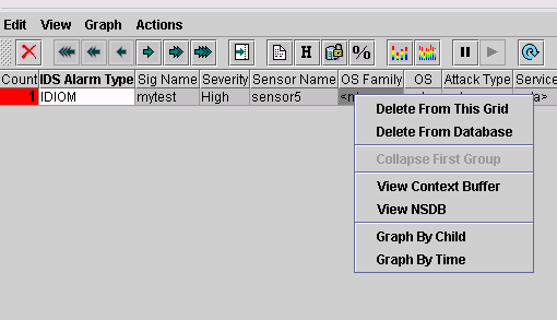
In the Event Viewer, highlight the alarm, right-click it and select either View Context Buffer or View NSDB to view more detailed information about the alarm.


Troubleshoot
This section provides information you can use to troubleshoot your configuration.
Troubleshooting Procedure
Complete these steps in order to troubleshoot.
-
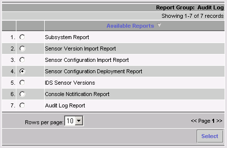
In the IDS MC, choose Reports > Generate.
Depending on the problem type, further details should be found in one of the seven available reports.
-
While Blocking utilizes the Command and Control port to configure the router access-lists, TCP Resets are sent from the sniffing interface of the Sensor. Ensure you have spanned the correct port, using the set span command on the switch, similar to this:
set span <src_mod/src_port><dest_mod/dest_port> both inpkts enable
banana (enable) set span 2/12 3/6 both inpkts enable
Overwrote Port 3/6 to monitor transmit/receive traffic of Port 2/12
Incoming Packets enabled. Learning enabled. Multicast enabled.
banana (enable)
banana (enable)
banana (enable) show span

Destination     : Port 3/6

!--- Connect to sniffing interface of the Sensor.

Admin Source    : Port 2/12

!--- In this case, connect to Ethernet1 of Router House.

Oper Source     : Port 2/12
Direction       : transmit/receive
Incoming Packets: enabled
Learning        : enabled
Multicast       : enabled
-
If TCP Reset is not working, login to the Sensor and enter the show event command.
Launch the attack, and check to see whether or not the alarm is triggered. If the alarm is triggered, check to ensure it is set for the action type TCP reset.

Related Information
Revision History
| Revision | Publish Date | Comments |
|---|---|---|
1.0 |
17-Oct-2008 |
Initial Release |
 Feedback
Contact Cisco
- Open a Support Case

- (Requires a Cisco Service Contract)