Trace Route in MPLS Network
Available Languages
Download Options
Bias-Free Language
The documentation set for this product strives to use bias-free language. For the purposes of this documentation set, bias-free is defined as language that does not imply discrimination based on age, disability, gender, racial identity, ethnic identity, sexual orientation, socioeconomic status, and intersectionality. Exceptions may be present in the documentation due to language that is hardcoded in the user interfaces of the product software, language used based on RFP documentation, or language that is used by a referenced third-party product. Learn more about how Cisco is using Inclusive Language.
Contents
Introduction
This document describes the Internet Control Message Protocol (ICMP) traceroute behavior in Multiprotocol Label Switching (MPLS) network and a quick comparison with LSP trace.
Background Information
In IP environment, any node when receives a packet and if the Time To Live (TTL) expires, it is expected to generate “TTL Exceeded” ICMP error message (Type=11, Code=0) and send it to the packet source address. This concept is leveraged in order to trace the IP path from source to destination by sending UDP packet with TTL sequentially starting from 1. It could be noted that the very basic requirements for this functionality are:
- Source address of the packet is reachable from the transit nodes
- ICMP is not filtered along the path
In MPLS environment, a transit provider LSR might not always have reachability to the source address and need some enhancement for ICMP handling in MPLS domain.
ICMP Traceroute in MPLS Network
The default behavior of any LSR on receiving a packet with TTL=1 on top label follows the traditional IP behavior of dropping the packet and trigger ICMP error message. In order to route the ICMP message to the source, the LSR will perform this:
- Buffer the label stack from incoming packet (the packet received with TTL=1)
- Generate ICMP error message with source as its own address and destination as source address from received packet.
- Append all labels from bottom of label stack (that was buffered earlier in step 1) with TTL=255 except the top one.
- Get the top label from buffered label stack and perform local LFIB lookup to get the label to swap and the associated next hop.
- Append the new label to the top of stack with TTL=255 and send across.
With this approach, the ICMP error message traverses from transit LSR to egress LER and then back to ingress LER to actual source.
ICMP Trace Triggered from PE to Remote PE
Here is a simple example which explains the behavior when ICMP trace is triggered from PE to remote PE within same MPLS domain:
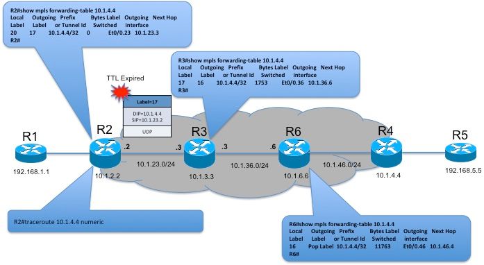
In this topology, when ICMP traceroute is triggered from R2 to 10.1.4.4, the first packet is sent with TTL of 1. R3 on receiving the packet will decrement the TTL to 0 and trigger ICMP generation mechanism.
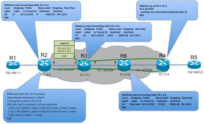
R3 will buffer the label stack and generate ICMP error message and include the incoming label stack from the buffer in ICMP payload. It further populate the IP header with source address from incoming interface of the labeled packet, destination address as the source of the labeled packet. The TTL is set to 255. It now pushes the label stack from the buffer and consults the LFIB table for forwarding action on top label. In this topology, the received label stack is 17. On performing a lookup in LFIB table, label 17 is swapped with label 16 and is forwarded towards nexthop R6. R6 in turn will pop the top label and forward to R4 which will IP forward the packet back towards R2.
As it could be noted in the traceroute output on R2, the incoming label will be listed by each hop along the path.
ICMP Trace Triggered from CE to Remote CE
Here is a simple example which explains the behavior when ICMP trace is triggered from CE to remote CE over MPLS domain:
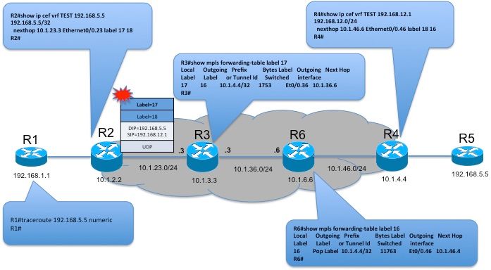
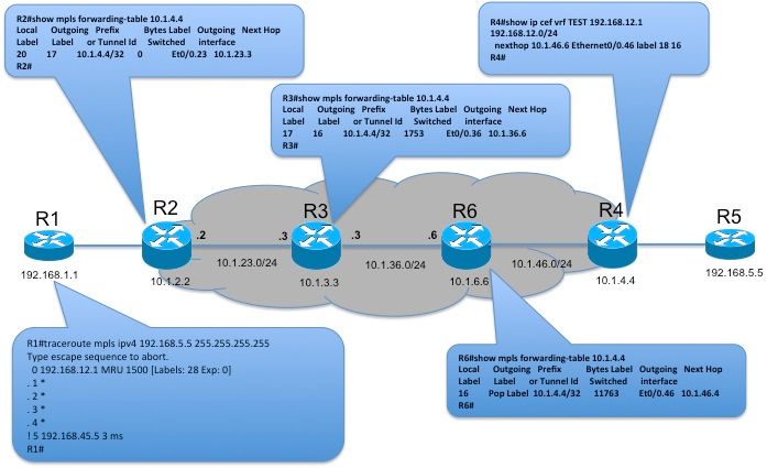
In this topology, when ICMP traceroute is triggered from R1 (CE) to 192.168.5.5 (remote CE), the first packet is sent with TTL of 1. This is normal IP packet and so R2 follows the traditional behavior of generating ICMP and sending directly to R1. The second packet sent with TTL=2 will expire at R3.
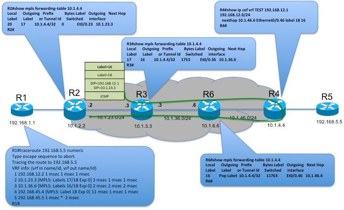
R3 will buffer the label stack and generate ICMP error message and include the incoming label stack from the buffer in ICMP payload. It further populate the IP header with source address from incoming interface of the labeled packet, destination address as the source of the labeled packet. The TTL is set to 255. It now pushes the label stack from the buffer and consults the LFIB table for forwarding action on top label. In the above topology, the received label stack is {17, 18}. On performing a lookup in LFIB table for top label, 17 will be swapped with label 16 and will be forwarded towards nexthop R6. R6 in turn will pop the top label and forward to R4. R4 will use the VRF label to identify the VRF and forward the packet back towards R1.
As it could be noted in the traceroute output on R1, the incoming label stack is listed by each hop along the path.
MPLS LSP Traceroute in MPLS Network
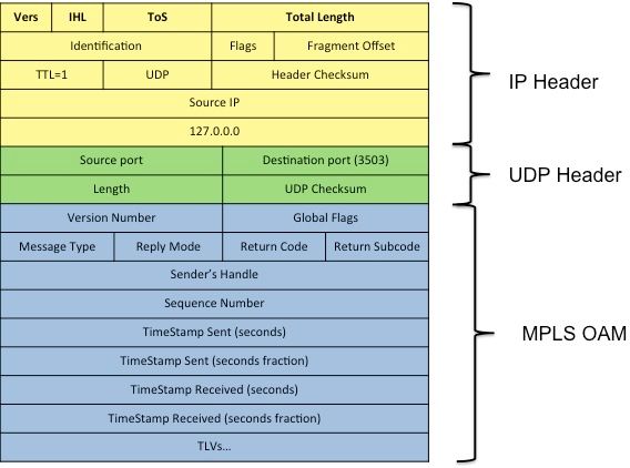
Unlike ICMP based traceroute, LSP traceroute uses the machinery defined in RFC4379. It uses IP/UDP encapsulation with destination address of request set to loopback address (127.0.0.0/8 range). It is expected that LSP Ping is to be triggered within the same MPLS domain and so reply will be directly sent to the Initiator.
When LSP traceroute (“traceroute mpls ipv4 <FEC>”) is triggered from any LSR, the details about the FEC to be validated will be included in a TLV as “Target FEC Stack” in MPLS Echo Request. This message will be sent with TTL on the Label stack sequentially starting from 1. Any transit LSR on receiving the packet and if the TTL expires will process the IP packet, as the destination address is loopback address. and punt to CPU for MPLS OAM processing.
Responder will optionally perform FEC validation by fetching the label(s) from label stack of received MPLS Echo Request and FEC details from Target FEC Stack TLV to validate the same against the local control plane information. In case of trace, Responder will include the downstream information like the Outgoing label and downstream neighbor address etc in a TLV as Downstream Mapping (DSMAP) TLV. (DSMAP will be deprecated by DDMAP as it is more flexible than DSMAP).
LSP Trace Triggered from PE to Remote PE
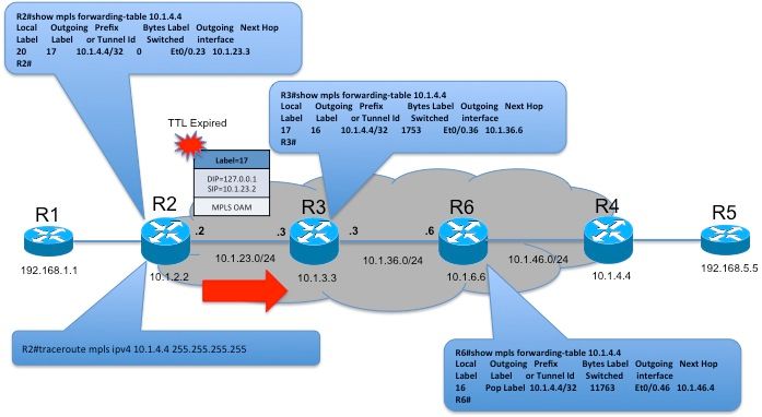
In this topology, LSP trace is triggered from R2 to validate the LSP to prefix 10.1.4.4/32. The TTL on the label will be set from 1. R3 on receiving it will punt to CPU for OAM processing.
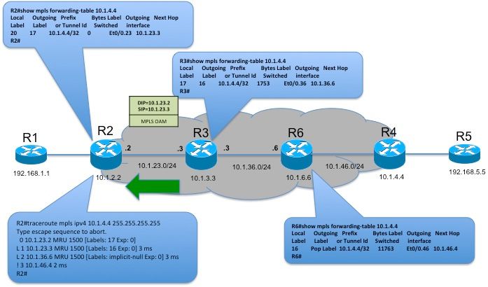
R3 will reply back to R2 with MPLS Echo Reply with DSMAP TLV carrying outgoing label 16 and additional information like downstream neighbor details. Unlike ICMP messages, MPLS Echo Reply will be directly forwarded from responder R3 to Initiator R2.
As it could be noted in the LSP traceroute output on R2, the outgoing label stack will be listed by each hop along the path. This is different from ICMP based traceroute where the label listed in output will be incoming label stack.
LSP Trace Triggered from CE to Remote CE
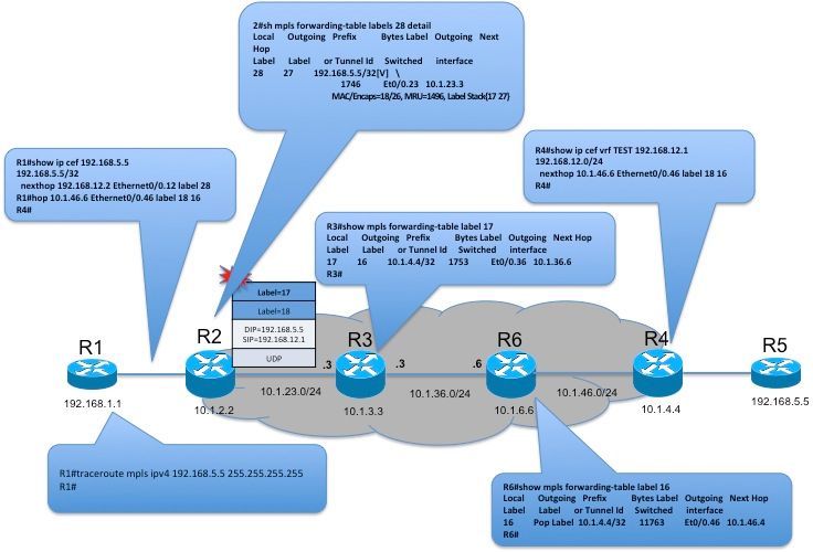
This is applicable in CSC like scenarios where MPLS is enabled between PE-CE. There are 2 challenges in executing LSP trace from CE to remote CE over Carrier MPLS domain as below:
- LSP Echo Reply will be directly sent to the Initiator. So responder MUST have reachability to Initiator. In above topology, R3 may not have reachability to R1 as it is in VRF.
- For each label in label stack, there should be relevant FEC details included in Target FEC Stack for validation. The FEC included by Initiator will be 1 while PE will push 2 labels. In above topology, R1 sends MPLS Echo Request with FEC={192.168.5.5/32} and include label 28 in the stack. Since R2 swaps label 28 with {17, 27}, R3 will receive the Request with 2 label in the stack while 1 FEC in TLV confusing FEC validation.
RFC6424 defines the concept of “FEC Stack change TLV” to tackle Issue 2. This TLV will be included in reply with relevant FEC as PUSH/POP that can be included by Initiator in subsequent Echo Request.
draft-ietf-mpls-lsp-ping-relay-reply defines the concept of carrying Relay Node Address stack in TLV that can be used by Responder to relay the response even though it does not have reachability to the Initiator.
These 2 issues are not currently supported in Cisco IOS® and so LSP trace from CE to remote CE will only list the ingress PE and remote CE. This is included just for completeness.
Related Information
Contributed by Cisco Engineers
- Nagendra Kumar NainarCisco TAC Engineer
Contact Cisco
- Open a Support Case

- (Requires a Cisco Service Contract)
 Feedback