Configuring and Troubleshooting a Cisco 1700 Router Using an Ethernet WIC as a PPPoE Client with NAT
Available Languages
Contents
Introduction
This document shows how to configure a Cisco 1700 using the Ethernet WAN Interface Card (WIC-1ENET) to act as a Point-to-Point Protocol over Ethernet (PPPoE) client with Network Address Translation (NAT).
Prerequisites
Requirements
There are no specific requirements for this document.
Components Used
The information in this document is based on these software and hardware versions:
-
Cisco IOS® Software Release 12.1(3) XT1 or later to support the Cisco 1700 WIC-1ENET.
-
For this sample configuration, the Cisco 6400 Universal Access Concentrator-Node Route Processor (UAC-NRP) was running Cisco IOS Software Release 12.1(3)DC1.
To support PPPoE, you must have the ADSL+PLUS feature set. The ADSL-only feature set does not support PPPoE on the Cisco 1700.
The information in this document was created from the devices in a specific lab environment. All of the devices used in this document started with a cleared (default) configuration. If your network is live, make sure that you understand the potential impact of any command.
Conventions
For more information on document conventions, refer to Cisco Technical Tips Conventions.
Background Theory
The WIC-1ENET is a 10BASE-T card developed for the Cisco 1700 series routers. The WIC-1ENET provides a second Ethernet interface for the Cisco 1700, which helps to use the rich functionality of Cisco IOS Software with any Digital Subscriber Line (DSL) or Cable modem.
The PPPoE client feature allows the PPPoE functionality to be moved to the router. Multiple PCs can be installed behind the Cisco 1700 Fast Ethernet interface and, before their traffic is sent to the PPPoE session, it can be encrypted, filtered, and so on, and NAT can run. Running PPPoE on the router removes the need of using PPPoE client software on the PCs.
Processor Requirements
Revision B5 of the MPC 860 Microprocessor is required. This processor is used in all Cisco 1700 series routers shipped after November 21, 1999. Cisco 1700 serial numbers starting with JAB0347XXXX have been manufactured with the Model MPC860 revision B5 microprocessor.
The date code is built into the serial number. The format is LLLYYWWSSSS, where:
-
LLL is the location at which the unit was built.
-
YY is the year that the unit was built (1997=01, 1998=02, 1999=03, 2000=04).
-
WW is the work week of the year that the unit was built.
-
SSSS is the serial number.
The processor version information is displayed at bootup. You can also verify the processor revision by issuing the show version command at the Router# prompt.
Memory Requirements
To run Cisco 1700 IOS images that support the Cisco WIC-1ENET, the router must have a minimum amount of Flash memory and DRAM. For details on the memory requirements for each image, refer to the Release Notes for the Cisco 1700 Series Routers for Cisco IOS Release 12.1(3)XT1.
WIC-1ENET Restrictions and Unsupported Features
-
WIC-1ENET is not supported in platforms other than the Cisco 1700.
-
Only a twisted pair RJ-45 connection is supported; there is no attachment unit interface (AUI) or BNC interface support.
-
There is no Auto Negotiation (Auto Sensing) between half-duplex and full-duplex modes.
-
WIC-1ENET cannot be used for TFTP file downloading while the host is in ROMMON.
-
WIC-1ENET is not recognized by the Cisco 1700 when it is in ROMMON mode.
-
Current Cisco IOS Software supports the WIC-1ENET only in Slot 0 of a Cisco 1700.
Configure
In this section, you are presented with the information to configure the features described in this document.
The PPPoE client is configured on the Cisco 1700 with the virtual private dial-up network (VPDN) commands. (VPDN commands are not needed for Cisco IOS Software Release 12.2(13)T or later.) Make sure that you configure these commands first.
Note: For information about changing the size of the maximum transmission unit (MTU), refer to Troubleshooting MTU Size in PPPoE Dialin Connectivity.
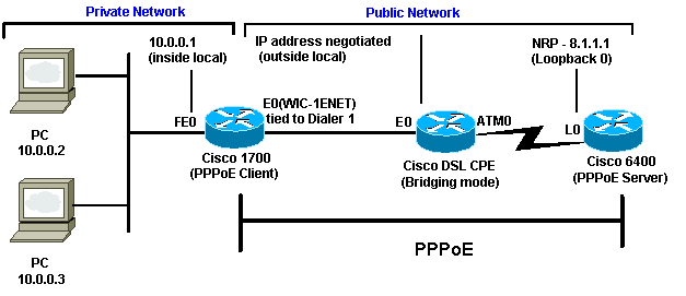
Network Diagram
This document uses this network setup:
Configurations
This document uses these configurations:
| Cisco 1700 |
|---|
! vpdn enable no vpdn logging ! vpdn-group pppoe request-dialin !--- The PPPoE client requests to establish !--- a session with the aggregation unit (6400 NRP). !--- These VPDN commands are not needed with !--- Cisco IOS Software Release 12.2(13)T or later. protocol pppoe ! int Dialer1 ip address negotiated encapsulation ppp ip mtu 1492 !--- The Ethernet MTU is 1500 by default !--- (1492 + PPPoE headers = 1500). ip nat outside dialer pool 1 !--- This ties to interface Ethernet0. dialer-group 1 ppp authentication chap callin ppp chap hostname <username> ppp chap password <password> ! !--- The ISP instructs you regarding !--- the type of authentication to use. !--- To change from PPP Challenge Handshake Authentication !--- Protocol(CHAP) to PPP Password Authentication Protocol (PAP), !--- replace these three lines: !--- ppp authentication chap callin !--- ppp chap hostname !--- ppp chap password !--- with these two lines: !--- ppp authentication pap callin. ppp pap sent-username <username> password <password> ! dialer-list 1 protocol ip permit ! !--- This is the internal Ethernet network. interface FastEthernet0 ip address 10.0.0.1 255.255.255.0 ip nat inside ! interface Ethernet0 pppoe enable pppoe-client dial-pool-number 1 !--- The PPPoE client code ties into a dialer !--- interface upon which a virtual-access !--- interface is cloned. ! !--- For NAT, you overload on the !--- Dialer1 interface and add a default route !--- out of the Dialer1 interface because !--- the IP address can change. ip nat inside source list 1 interface Dialer1 overload ip classless ip route 0.0.0.0 0.0.0.0 dialer1 no ip http server ! dialer-list 1 protocol ip permit access-list 1 permit 10.0.0.0 0.0.0.255 !--- This is for NAT. ! |
| Cisco 6400 |
|---|
*** local ppp user !--- Or, you can use AAA. username <username> password <password> !--- Begin with the VPDN commands. !--- Notice that you are binding the PPPoE here to !--- a virtual-template instead of on the ATM interface. !--- You cannot (at this time) use more than one !--- virtual-template (or VPDN group) for PPPoE !--- beginning with the VPDN commands. vpdn enable no vpdn logging ! vpdn-group pppoe accept-dialin !--- This is PPPoE server mode. protocol pppoe virtual-template 1 ! ! interface ATM0/0/0 no ip address no atm ilmi-keepalive hold-queue 500 in !--- The binding to the virtual-template !--- interface is configured in the VPDN group. ! interface ATM0/0/0.182 point-to-point pvc 1/82 encapsulation aal5snap !--- You need the command on the server side. protocol pppoe ! ! !--- Virtual-template is used instead of dialer interface. ! interface Virtual-Template1 ip unnumbered Loopback10 ip mtu 1492 peer default ip address pool ippool ppp authentication chap ! ! interface Loopback10 ip address 8.8.8.1 255.255.255.0 ! ip local pool ippool 9.9.9.1 9.9.9.5 |
Verify
There is currently no verification procedure available for this configuration.
Debugging the PPPoE Client
This section provides information you can use to troubleshoot your configuration.
To debug the Cisco 1700 (PPPoE client), you must consider the protocol stack.
-
Layer 4 - PPP layer
-
Layer 3 - Ethernet layer
-
Layer 2 - ATM layer
-
Layer 1 - DSL physical layer
You could troubleshoot beginning at the bottom. Since the DSL and ATM layers are occurring at the DSL Customer Premises Equipment (CPE), you need to troubleshoot only the Ethernet and PPP layers for the Cisco 1700, as shown below.
Ethernet Layer
Complete Ethernet frames are in the ATM adaptation layer 5 (AAL5) Subnetwork Access Protocol (SNAP) packets. There is no debug Ethernet packet command, but you should perform some VPDN debugs (PPPoE debugs for Cisco IOS Software Release 12.2(13)T or later) to see the PPPoE frames.
For reference, an Ethernet frame which is a PPPoE frame contains one of two Ethertypes:
-
0x8863 Ethertype = PPPoE control packet (handles the PPPoE session)
-
0x8864 Ethertype = PPPoE data packet (contains PPP packets)
One important note is that there are two sessions in PPPoE: the PPPoE session which is a VPDN Layer Two Tunneling Protocol (L2TP)-type session, and the PPP session. So, to establish PPPoE, there is a PPPoE session establishment phase and a PPP session establishment phase.
Termination usually involves a PPP termination phase and a PPPoE termination phase.
The PPPoE establishment phase consists of identifying the MAC addresses of the PPPoE client and server and assigning a session ID. After that is complete, the normal PPP establishment occurs just like any other PPP connection.
To debug, you can use VPDN PPPoE debugs (PPPoE debugs for Cisco IOS Software Release 12.2(13)T or later) to determine if the PPPoE connect phase is successful.
# debug vpdn pppoe-events (debug pppoe events)

06:17:58: Sending PADI: vc=1/1

!--- A broadcast Ethernet frame (in this case, encapsulated in ATM) !--- requests a PPPoE server, "Are there any PPPoE servers out there?"


06:18:00:  PPPOE: we've got our pado and the pado timer went off

!--- This is a unicast reply from a PPPoE server (very similar to !--- a DHCP offer).


06:18:00: OUT PADR from PPPoE tunnel

!--- This is a unicast reply accepting the offer.


06:18:00: IN PADS from PPPoE tunnel

!--- This is a confirmation that completes the establishment.
The PPP establishment now begins, as in any other PPP initiation. After the PPPoE session is established, you can issue show vpdn commands to get the status.
# show vpdn (show pppoe session)
%No active L2TP tunnels
%No active L2F tunnels

PPPoE Tunnel and Session Information Total tunnels 1 sessions 1

PPPoE Tunnel Information

Session count: 1

PPPoE Session Information
SID        RemMAC          LocMAC       Intf    VASt   OIntf    VC
1       0050.7359.35b7  0001.96a4.84ac  Vi1     UP     AT0    1    1
You can get packet count information using the show vpdn session all (show pppoe session all) command.
show vpdn session all (show pppoe session all)
%No active L2TP tunnels
%No active L2F tunnels

PPPoE Session Information Total tunnels 1 sessions 1

session id: 1
local MAC address: 0001.96a4.84ac, remote MAC address: 0050.7359.35b7
virtual access interface: Vi1, outgoing interface: AT0, vc: 1/1
    1656 packets sent, 1655 received, 24516 bytes sent, 24486 received
Other debug commands:
-
debug vpdn pppoe-data (debug pppoe data)
-
debug pppoe-errors (debug pppoe errors)
-
debug pppoe-packets (debug pppoe packets)
PPP Layer
After the PPPoE session has been established, the PPP debugs are the same as for any other PPP establishment.
The same debug ppp negotiation and debug ppp authentication commands are used. Here is sample output:
Note: In this sample, the host name is "client1", and the name of the remote Cisco 6400 is "nrp-b".
06:36:03: Vi1 PPP: Treating connection as a callout
06:36:03: Vi1 PPP: Phase is ESTABLISHING, Active Open [0 sess, 1 load]
06:36:03: Vi1 PPP: No remote authentication for call-out
06:36:03: Vi1 LCP: O CONFREQ [Closed] id 1 len 10
06:36:03: Vi1 LCP:    MagicNumber 0x03013D43 (0x050603013D43)
06:36:03: Vi1 LCP: I CONFACK [REQsent] id 1 len 10
06:36:03: Vi1 LCP:    MagicNumber 0x03013D43 (0x050603013D43)
06:36:05: Vi1 LCP: I CONFREQ [ACKrcvd] id 2 len 15
06:36:05: Vi1 LCP:    AuthProto CHAP (0x0305C22305)
06:36:05: Vi1 LCP:    MagicNumber 0x65E315E5 (0x050665E315E5)
06:36:05: Vi1 LCP: O CONFACK [ACKrcvd] id 2 len 15
06:36:05: Vi1 LCP:    AuthProto CHAP (0x0305C22305)
06:36:05: Vi1 LCP:    MagicNumber 0x65E315E5 (0x050665E315E5)
06:36:05: Vi1 LCP: State is Open
06:36:05: Vi1 PPP: Phase is AUTHENTICATING, by the peer [0 sess, 1 load]
06:36:05: Vi1 CHAP: I CHALLENGE id 9 len 26 from "nrp-b"
06:36:05: Vi1 CHAP: Using alternate hostname client1
06:36:05: Vi1 CHAP: Username nrp-b not found
06:36:05: Vi1 CHAP: Using default password
06:36:05: Vi1 CHAP: O RESPONSE id 9 len 28 from "client1"
06:36:05: Vi1 CHAP: I SUCCESS id 9 len 4
06:36:05: Vi1 PPP: Phase is FORWARDING [0 sess, 1 load]
06:36:05: Vi1 PPP: Phase is AUTHENTICATING [0 sess, 1 load]
06:36:05: Vi1 PPP: Phase is UP [0 sess, 1 load]
06:36:05: Vi1 IPCP: O CONFREQ [Closed] id 1 len 10
06:36:05: Vi1 IPCP:    Address 0.0.0.0 (0x030600000000)
06:36:05: Vi1 CDPCP: O CONFREQ [Closed] id 1 len 4
06:36:05: Vi1 IPCP: I CONFREQ [REQsent] id 1 len 10
06:36:05: Vi1 IPCP:    Address 8.8.8.1 (0x030608080801)
06:36:05: Vi1 IPCP:    Address 8.8.8.1 (0x030608080801)
06:36:05: Vi1 IPCP:    Address 9.9.9.2 (0x030609090902)
06:36:05: Vi1 IPCP: O CONFREQ [ACKsent] id 2 len 10
06:36:05: Vi1 IPCP:    Address 9.9.9.2 (0x030609090902)
06:36:05: Vi1 LCP: I PROTREJ [Open] id 3 len 10 protocol CDPCP (0x820701010004)
06:36:05: Vi1 CDPCP: State is Closed
06:36:05: Vi1 IPCP: I CONFACK [ACKsent] id 2 len 10
06:36:05: Vi1 IPCP:    Address 9.9.9.2 (0x030609090902)
06:36:05: Vi1 IPCP: State is Open
06:36:05: Di1 IPCP: Install negotiated IP interface address 9.9.9.2
06:36:05: Di1 IPCP: Install route to 8.8.8.1
06:36:06: %LINEPROTO-5-UPDOWN: Line protocol on Interface Virtual-Access1, changed
 state to up
Debugging the PPPoE Server
To debug the Cisco 6400 (the PPPoE server), you can use the same bottom-up procedure used for the Cisco 1700 (the PPPoE client).
-
Layer 4 - PPP layer
-
Layer 3 - Ethernet layer
-
Layer 2 - ATM layer
-
Layer 1 - DSL physical layer
The difference is that now you troubleshoot the DSL layer on the digital subscriber line access multiplier (DSLAM) and the ATM layer on the Cisco 6400, as shown below.
DSL Physical Layer
To check the DSL physical layer, you need to see the DSL statistics on the DSLAM. For Cisco DSLAMs, the show dsl interface command can be used.
ATM Layer
On the Cisco 6400 side, you can also use the debug atm packet command and enable the Cisco 6400 for a specific PVC.
debug atm packet interface atm 0/0/0.182 vc 1/82
You should see output similar to the following, with the same Type, SAP, CTL, and OUI fields showing that the incoming ATM packet is AAL5 SNAP.
4d04h: ATM0/0/0.182(I):
VCD:0x3 VPI:0x1 VCI:0x52 Type:0x900 SAP:AAAA CTL:03 OUI:0080C2 TYPE:0007 Length:0x30
4d04h: 0000 0001 96A4 84AC 0050 7359 35B7 8864 1100 0001 000E C021 0A2E 000C 65E3
4d04h: 15E5 0000 0000
Note: You do not see outgoing packets with this command because of the way that the packets are processed.
Ethernet Layer
The same VPDN show and debug commands used on the Cisco 1700 can be used on the Cisco 6400 to look at the PPPoE establishment.
# debug vpdn pppoe-events (debug pppoe events)

4d04h: IN PADI from PPPoE tunnel

4d04h: OUT PADO from PPPoE tunnel

4d04h: IN PADR from PPPoE tunnel

4d04h: PPPoE: Create session
4d04h: PPPoE: VPN session created.

4d04h: OUT PADS from PPPoE tunnel


# show vpdn (show pppoe session)
%No active L2TP tunnels
%No active L2F tunnels

PPPoE Tunnel and Session Information Total tunnels 1 sessions 1

PPPoE Tunnel Information

Session count: 1
PPPoE Session Information
SID        RemMAC          LocMAC       Intf    VASt   OIntf    VC
1       0001.96a4.84ac  0050.7359.35b7  Vi4     UP     AT0/0/0 1   82


nrp-b#
show vpdn session all (show pppoe session all)
%No active L2TP tunnels
%No active L2F tunnels

PPPoE Session Information Total tunnels 1 sessions 1

session id: 1
local MAC address: 0050.7359.35b7, remote MAC address: 0001.96a4.84ac
virtual access interface: Vi4, outgoing interface: AT0/0/0, vc: 1/82
    30 packets sent, 28 received, 422 bytes sent, 395 received
These are other debug commands:
-
debug vpdn pppoe-data (debug pppoe data)
-
debug pppoe-errors (debug pppoe data)
-
debug pppoe-packets (debug pppoe packets)
PPP Layer
This is a PPP debug output from the Cisco 6400 that corresponds to the earlier debug from the Cisco 1700:
debug ppp negotiation and debug ppp authentication

4d04h: Vi2 PPP: Treating connection as a dedicated line
4d04h: Vi2 PPP: Phase is ESTABLISHING, Active Open [0 sess, 1 load]
4d04h: Vi2 LCP: O CONFREQ [Closed] id 1 len 15
4d04h: Vi2 LCP:    AuthProto CHAP (0x0305C22305)
4d04h: Vi2 LCP:    MagicNumber 0x65F62814 (0x050665F62814)
4d04h: Vi2 LCP: I CONFREQ [REQsent] id 1 len 10
4d04h: Vi2 LCP:    MagicNumber 0x03144FF9 (0x050603144FF9)
4d04h: Vi2 LCP: O CONFACK [REQsent] id 1 len 10
4d04h: Vi2 LCP:    MagicNumber 0x03144FF9 (0x050603144FF9)
4d04h: Vi3 LCP: I ECHOREQ [Open] id 60 len 8 magic 0xA60C0000
4d04h: Vi3 LCP: O ECHOREP [Open] id 60 len 8 magic 0x51A0BEF6
4d04h: Vi2 LCP: TIMEout: State ACKsent
4d04h: Vi2 LCP: O CONFREQ [ACKsent] id 2 len 15
4d04h: Vi2 LCP:    AuthProto CHAP (0x0305C22305)
4d04h: Vi2 LCP:    MagicNumber 0x65F62814 (0x050665F62814)
4d04h: Vi2 LCP: I CONFACK [ACKsent] id 2 len 15
4d04h: Vi2 LCP:    AuthProto CHAP (0x0305C22305)
4d04h: Vi2 LCP:    MagicNumber 0x65F62814 (0x050665F62814)
4d04h: Vi2 LCP: State is Open
4d04h: Vi2 PPP: Phase is AUTHENTICATING, by this end [0 sess, 1 load]
4d04h: Vi2 CHAP: O CHALLENGE id 10 len 26 from "nrp-b"
4d04h: Vi2 CHAP: I RESPONSE id 10 len 28 from "client1"
4d04h: Vi2 PPP: Phase is FORWARDING [0 sess, 1 load]
4d04h: Vi2 PPP: Phase is AUTHENTICATING [0 sess, 1 load]
4d04h: Vi2 CHAP: O SUCCESS id 10 len 4
4d04h: Vi2 PPP: Phase is UP [0 sess, 1 load]
4d04h: Vi2 IPCP: O CONFREQ [Closed] id 1 len 10
4d04h: Vi2 IPCP:    Address 8.8.8.1 (0x030608080801)
4d04h: Vi2 IPCP: I CONFREQ [REQsent] id 1 len 10
4d04h: Vi2 IPCP:    Address 0.0.0.0 (0x030600000000)
4d04h: Vi2 IPCP: Pool returned 9.9.9.2
4d04h: Vi2 IPCP: O CONFNAK [REQsent] id 1 len 10
4d04h: Vi2 IPCP:    Address 9.9.9.2 (0x030609090902)
4d04h: Vi2 CDPCP: I CONFREQ [Not negotiated] id 1 len 4
4d04h: Vi2 LCP: O PROTREJ [Open] id 3 len 10 protocol CDPCP (0x820701010004)
4d04h: Vi2 IPCP: I CONFACK [REQsent] id 1 len 10
4d04h: Vi2 IPCP:    Address 8.8.8.1 (0x030608080801)
4d04h: Vi2 IPCP: I CONFREQ [ACKrcvd] id 2 len 10
4d04h: Vi2 IPCP:    Address 9.9.9.2 (0x030609090902)
4d04h: Vi2 IPCP: O CONFACK [ACKrcvd] id 2 len 10
4d04h: Vi2 IPCP:    Address 9.9.9.2 (0x030609090902)
4d04h: Vi2 IPCP: State is Open
4d04h: Vi2 IPCP: Install route to 9.9.9.2
4d04h: %LINEPROTO-5-UPDOWN: Line protocol on Interface Virtual-Access2, changed
 state to up
 Feedback