Configure Inter VLAN Routing with Catalyst Switches
Available Languages
Download Options
Bias-Free Language
The documentation set for this product strives to use bias-free language. For the purposes of this documentation set, bias-free is defined as language that does not imply discrimination based on age, disability, gender, racial identity, ethnic identity, sexual orientation, socioeconomic status, and intersectionality. Exceptions may be present in the documentation due to language that is hardcoded in the user interfaces of the product software, language used based on RFP documentation, or language that is used by a referenced third-party product. Learn more about how Cisco is using Inclusive Language.
Introduction
This document describes how to configure Inter VLAN routing with Cisco Catalyst series switches.
Prerequisites
Requirements
Ensure that you meet these requirements before you attempt this configuration:
-
Knowledge of how to create VLANs
For more information, refer to Create Ethernet VLANs on Catalyst Switches.
-
Knowledge of how to create Trunk links
Components Used
The information in this document is based on these software and hardware versions:
-
Catalyst 3850 that runs Cisco IOS® XE Software Release 16.12.7
-
Catalyst 4500 that runs Cisco IOS® Software Release 03.09.00E
The information in this document was created from the devices in a specific lab environment. All of the devices used in this document started with a cleared (default) configuration. If your network is live, ensure that you understand the potential impact of any command.
Conventions
Refer to Cisco Technical Tips Conventions for more information on document conventions.
Related Products
This configuration can also be used with these hardware and software versions:
-
Any Catalyst 3k/9k switch and later
-
Any Catalyst switch model, used as the access layer switch
Background Information
This document provides a sample configuration for Inter VLAN routing with a Catalyst 3850 series switch in a typical network scenario. The document uses two Catalyst 4500 series switch as Layer 2 (L2) switches that connect directly to the Catalyst 3850. The Catalyst 3850 configuration also has a default route for all traffic that goes to the Internet when the next hop points to a Cisco router. You can substitute the Internet Gateway with a firewall or other routers model.
Note: The configuration from the Internet Gateway router is not relevant, so this document does not cover the configuration.
In a switched network, VLANs separate devices into different collision domains and Layer 3 (L3) subnets. Devices within a VLAN can communicate with each other without the need for routing. Devices in separate VLANs require a routing device to communicate with each other.
L2-only switches require an L3 routing device to provide communication between VLANs. The device is either external to the switch or in another module on the same chassis. A new breed of switches incorporate routing capability within the switch. An example is the 3850. The switch receives a packet, determines that the packet belongs to another VLAN, and sends the packet to the appropriate port on the destination VLAN.
A typical network design segments the network based on the group or function to which the device belongs. For example, the engineering VLAN only has devices that relate to the engineering department, and the finance VLAN only has devices that relate to finance. If you enable routing, the devices in each VLAN can talk to one another without the need for all the devices to be in the same broadcast domain. Such a VLAN design also has an additional benefit. The design allows the administrator to restrict communication between VLANs with use of access lists. For example, you can use access lists to restrict the engineering VLAN from access to devices on the finance VLAN.
Refer to this document that demonstrates how to configure the Inter VLAN routing on a Catalyst 3550 series switch for more information, How To Configure Inter VLAN Routing On Layer 3 Switches .
Configure
In this section, you are presented with the information to configure the features described in this document.
Note: Use the Cisco Support Tools to find more information on the commands used here. Only registered Cisco users have access to tools like this and other internal information.
Network Diagram
This document uses this network setup:
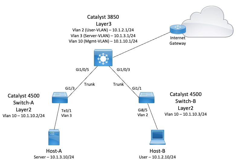
In this diagram, a small sample network with the Catalyst 3850 provides Inter VLAN routing between the various segments. The Catalyst 3850 switch can act as an L2 device with the disablement of IP routing. In order to make the switch function as an L3 device and provide Inter VLAN routing, make sure that ip routing is enabled globally.
These are the three VLANs defined by the user:
-
VLAN 2 — User-VLAN
-
VLAN 3 — Server-VLAN
-
VLAN 10 — Mgmt-VLAN
The default gateway configuration on each server and host device must be the VLAN interface IP address that corresponds on the 3850. For example, for Servers, the default gateway is 10.1.3.1. The access layer switches, which are the Catalyst 4500, are trunked to the Catalyst 3850 switch.
The default route for the Catalyst 3850 points to the Cisco router, and this is used to route traffic destined for the Internet. Therefore, traffic for which the 3850 does not have a route in the routing table is forwarded to the Cisco Router for additional process.
Practical Tips
-
Ensure that the native VLAN for an 802.1Q trunk is the same on both ends of the trunk link. If the native VLAN on one end of the trunk is different than the native VLAN on the other end, the traffic of the native VLANs on both sides cannot be transmitted correctly on the trunk. This failure to transmit correctly can imply some connectivity issues in your network.
-
Separate the management VLAN from the User or Server VLAN, as in this diagram. The management VLAN is different from the user or server VLAN. With this separation, any broadcast/packet storm that occurs in the user or server VLAN does not affect the management of switches.
-
Do not use VLAN 1 for management. All ports in Catalyst switches default to VLAN 1, and any devices that connect to ports that are not configured are in VLAN 1. The use of VLAN 1 for management can cause potential issues for the management of switches.
-
Use a Layer 3 (routed) port to connect to the default gateway port. In this example, you can easily replace a Cisco router with a firewall that connects to the Internet gateway router.
-
This example configures a static default route on the 3850 towards the Csco Router to reach the Internet. This setup is best if there is only one route to the Internet. Make sure to configure static routes, preferably summarized, on the gateway router for subnets that can be reached by the Catalyst 3850. This step is very important because this configuration does not use routing protocols.
-
If you have two Catalyst 3850 switches in your network, you can dually connect the access layer switches to the 3850 switches, and then run Hot Standby Router Protocol (HSRP) between the switches to provide redundancy in the network.
-
If you need additional bandwidth for the uplink ports, you can configure EtherChannels. The EtherChannel also provides link redundancy in the case of a link failure.
Configurations
This document uses these configurations:
-
Catalyst 3850
-
Catalyst 4500-A
-
Catalyst 4500-B
| Catalyst 3850 |
|---|
|
Note: For this example, VLAN Trunk Protocol (VTP) was set to off on all the switches. This switch uses the next commands to set VTP as off and to create the three VLANs that the user defined from global configuration mode:
SW_3850(config)#vtp mode off
Setting device to VTP Off mode for VLANS.
SW_3850(config)#vlan 2
SW_3850(config-vlan)#name User_VLAN
SW_3850(config-vlan)#exit
SW_3850(config)#vlan 3
SW_3850(config-vlan)#name Server_VLAN
SW_3850(config-vlan)#exit
SW_3850(config)#vlan 10
SW_3850(config-vlan)#name Mgmt_VLAN
SW_3850(config-vlan)#exit
SW_3850(config)#end
| Catalyst 4500-A |
|---|
|
| Catalyst 4500-B |
|---|
|
Verify
This section provides information you can use to confirm your configuration works properly.

Note: The Cisco CLI Analyzer Tool can help troubleshoot and check the overall health of your Cisco-supported software with this smart SSH client that uses integrated TAC tools and knowledge.
Note: For details on CLI commands, see the Command Reference Guides for specific switching platform.
Note: Only registered Cisco users have access to tools like this and other internal information.
Catalyst 3850
-
show vtp status
SW_3850#show vtp status
VTP Version capable             : 1 to 3
VTP version running             : 1
VTP Domain Name                 :
VTP Pruning Mode                : Disabled
VTP Traps Generation            : Disabled
Device ID                       : bc67.1c5d.3800
Configuration last modified by 10.0.0.10 at 0-0-00 00:00:00

Feature VLAN:
--------------
VTP Operating Mode                : Off
Maximum VLANs supported locally   : 1005
Number of existing VLANs          : 8
Configuration Revision            : 0
MD5 digest                        : 0x7E 0xC3 0x8D 0x91 0xC8 0x53 0x42 0x14
                                    0x79 0xA2 0xDF 0xE9 0xC0 0x06 0x1D 0x7D
-
show interfaces trunk
SW_3850#show interfaces trunk

Port        Mode             Encapsulation  Status        Native vlan
Gi1/0/3     on               802.1q         trunking      1
Gi1/0/5     on               802.1q         trunking      1

Port        Vlans allowed on trunk
Gi1/0/3     1-4094
Gi1/0/5     1-4094

Port        Vlans allowed and active in management domain
Gi1/0/3     1-3,10
Gi1/0/5     1-3,10

Port        Vlans in spanning tree forwarding state and not pruned
Gi1/0/3     1-3,10
Gi1/0/5     1,3,10
-
show ip route
SW_3850#show ip route
Codes: L - local, C - connected, S - static, R - RIP, M - mobile, B - BGP
       D - EIGRP, EX - EIGRP external, O - OSPF, IA - OSPF inter area
       N1 - OSPF NSSA external type 1, N2 - OSPF NSSA external type 2
       E1 - OSPF external type 1, E2 - OSPF external type 2, m - OMP
       n - NAT, Ni - NAT inside, No - NAT outside, Nd - NAT DIA
       i - IS-IS, su - IS-IS summary, L1 - IS-IS level-1, L2 - IS-IS level-2
       ia - IS-IS inter area, * - candidate default, U - per-user static route
       H - NHRP, G - NHRP registered, g - NHRP registration summary
       o - ODR, P - periodic downloaded static route, l - LISP
       a - application route
       + - replicated route, % - next hop override, p - overrides from PfR

Gateway of last resort is 10.100.100.2 to network 0.0.0.0

S*    0.0.0.0/0 [1/0] via 10.100.100.2
      10.0.0.0/8 is variably subnetted, 8 subnets, 2 masks
C        10.1.2.0/24 is directly connected, Vlan2
L        10.1.2.1/32 is directly connected, Vlan2
C        10.1.3.0/24 is directly connected, Vlan3
L        10.1.3.1/32 is directly connected, Vlan3
C        10.1.10.0/24 is directly connected, Vlan10
L        10.1.10.1/32 is directly connected, Vlan10
C        10.100.100.0/24 is directly connected, GigabitEthernet1/0/2
L        10.100.100.1/32 is directly connected, GigabitEthernet1/0/2
Catalyst 4500-A
-
show vtp status
Switch-A#show vtp status
VTP Version capable             : 1 to 3
VTP version running             : 2
VTP Domain Name                 : cisco.com
VTP Pruning Mode                : Disabled
VTP Traps Generation            : Disabled
Device ID                       : 6400.f13e.dc40
Configuration last modified by 10.1.10.2 at 0-0-00 00:00:00

Feature VLAN:
--------------
VTP Operating Mode                : Off
Maximum VLANs supported locally   : 1005
Number of existing VLANs          : 32
Configuration Revision            : 0
MD5 digest                        : 0x0B 0x61 0x4F 0x9B 0xCD 0x1B 0x37 0x55
                                    0xAB 0x0C 0xC1 0x4B 0xF8 0xDE 0x33 0xB3
-
show interfaces trunk
Switch-A#show interfaces trunk

Port        Mode             Encapsulation  Status        Native vlan
Gi1/3       on               802.1q         trunking      1

Port        Vlans allowed on trunk
Gi1/3       1-4094

Port        Vlans allowed and active in management domain
Gi1/3       1,3,10

Port        Vlans in spanning tree forwarding state and not pruned
Gi1/3       1,3,10
Catalyst 4500-B
-
show vtp status
Switch-B#show vtp status
VTP Version capable             : 1 to 3
VTP version running             : 1
VTP Domain Name                 :
VTP Pruning Mode                : Disabled
VTP Traps Generation            : Disabled
Device ID                       : 6c20.5606.3540
Configuration last modified by 10.1.10.3 at 11-15-22 10:42:29

Feature VLAN:
--------------
VTP Operating Mode                : Off
Maximum VLANs supported locally   : 1005
Number of existing VLANs          : 7
Configuration Revision            : 0
MD5 digest                        : 0xEC 0xB4 0x8D 0x46 0x94 0x95 0xE0 0x8F
                                    0xEE 0x1E 0xC7 0x9F 0x26 0x88 0x49 0x9F
-
show interfaces trunk
Switch-B#show interfaces trunk

Port        Mode             Encapsulation  Status        Native vlan
Gi1/1       on               802.1q         trunking      1

Port        Vlans allowed on trunk
Gi1/1       1-4094

Port        Vlans allowed and active in management domain
Gi1/1       1-2,10

Port        Vlans in spanning tree forwarding state and not pruned
Gi1/1       1-2,10
Troubleshoot
Use this section to troubleshoot your configuration.
Troubleshoot Procedure
Use these instructions:
-
If you are not able to ping devices within the same VLAN, check the VLAN assignment of the source and destination ports to make sure that the source and destination are in the same VLAN.
In order to check the VLAN assignment, issue the show interface status command for Cisco IOS Software.
If the source and destination are not in the same switch, make sure that you have configured the trunks properly. In order to check the configuration, issue the show interfaces trunk command.
-
Also, check that the native VLAN matches on either side of the trunk link. Make sure that the subnet mask matches between the source and destination devices.
-
If you are not able to ping devices in different VLANs, make sure that you can ping the respective default gateway. (See Step 1.)
Also, make sure that the default gateway of the device points to the correct VLAN interface IP address. Ensure that the subnet mask matches.
-
If you are not able to reach the Internet, make sure that the default route on the 3850 points to the correct IP address, and that the subnet address matches the Internet Gateway router.
In order to check, issue the show ip interface interface-id command. Make sure that the Internet Gateway router has routes to the Internet and the internal networks.
Related Information
Revision History
| Revision | Publish Date | Comments |
|---|---|---|
3.0 |
23-Jan-2024 |
Updated SEO and Formatting. |
2.0 |
21-Dec-2022 |
Updated format and usage. Recertification. |
1.0 |
15-Mar-2003 |
Initial Release |
Contributed by Cisco Engineers
- Julio JimenezProject Manager
 Feedback
Contact Cisco
- Open a Support Case

- (Requires a Cisco Service Contract)