Cisco ACI Design Guide for Telco Data Center Deployments
Available Languages
Bias-Free Language
The documentation set for this product strives to use bias-free language. For the purposes of this documentation set, bias-free is defined as language that does not imply discrimination based on age, disability, gender, racial identity, ethnic identity, sexual orientation, socioeconomic status, and intersectionality. Exceptions may be present in the documentation due to language that is hardcoded in the user interfaces of the product software, language used based on RFP documentation, or language that is used by a referenced third-party product. Learn more about how Cisco is using Inclusive Language.
Mobile operators around the world are observing unprecedented growth in mobile data subscribers and bandwidth usage. Data consumption is expected to grow exponentially with new technologies such as Internet of Things (IoT), increased use of mobile video, online gaming, and 5G. The current model for building a network is becoming outdated; it is not suited for today’s more dynamic, application-driven environment. Operators are looking for a new software-defined model to ensure they remain competitive, delivering new services faster while decreasing both capital and operating expenses.
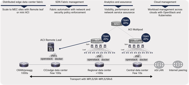
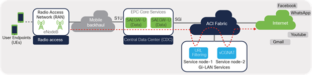
This software-defined approach—an architecture built on a foundation of virtualization, disaggregation, decoupling and automation—enables operators to meet these new application and operational demands, reduce time to market, and deliver differentiated user experiences. Figure 1 shows the architecture of a modern distributed telco cloud landscape. A distributed telco cloud, essentially, is a virtualized telco infrastructure built using data-center, cloud, and virtualization technologies, spanning from centralized telco data centers all the way to the edge locations that are closer to the consumers.
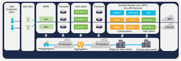
Distributed telco cloud architecture
Virtualization is fundamental to the framework that enables disaggregating software from the underlying hardware and offers benefits such as agility and quicker time to market. Virtualization is realized through Network Functions Virtualization Infrastructure (NFVI) solutions such as the Cisco® Virtual Infrastructure Manager (CVIM). Evolved Packet Core (EPC) functions and other radio functions are virtualized and hosted as Virtual Machines (VMs) or containers as Virtual Network Functions (VNFs).
The decoupling of the control and user plane (control-plane user-plane separation, or CUPS) for the evolved packet core enables distributed architecture, where certain functions (that is, user-plane functions) can be placed closer to the user at the edge or aggregation locations, enhancing the user experience.
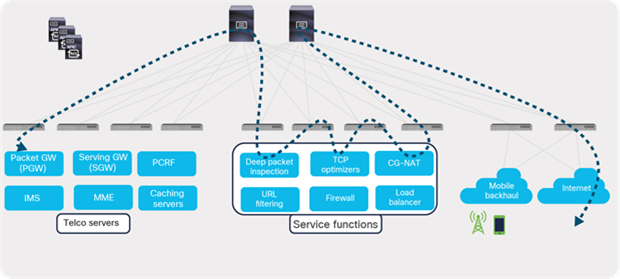
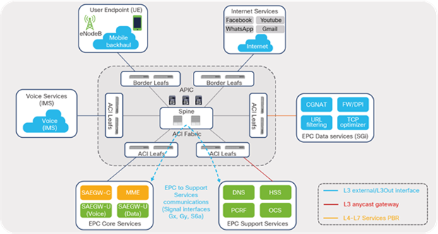
The Cisco ACI solution aligns with the distributed telco cloud model and 5G architecture and can host a wide range of core and edge services in the telco data-center landscape. Figure 2 shows the Cisco ACI fabric solution providing connectivity to various building blocks of core services in the central or regional telco data center.
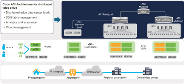
Cisco ACI architecture for distributed data centers
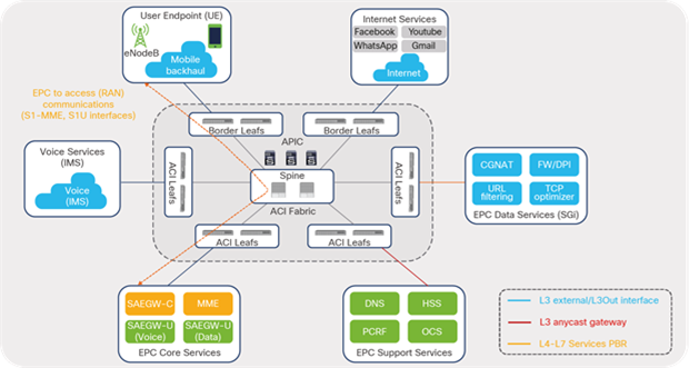
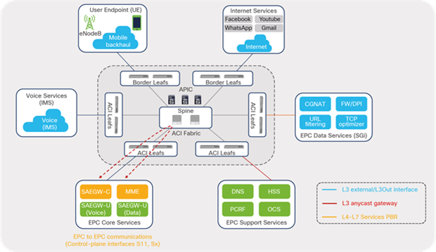
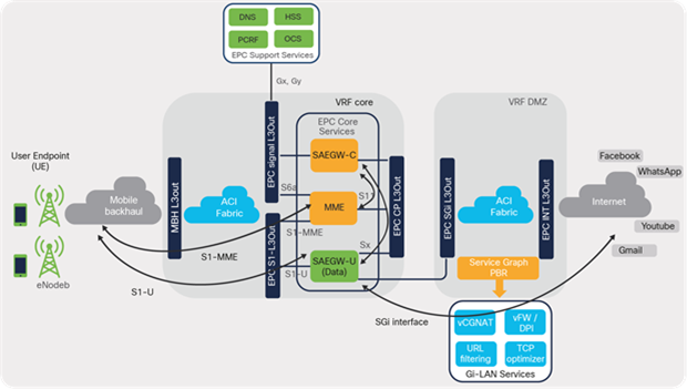
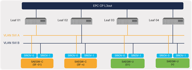
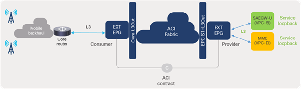
This guide describes how to design an ACI fabric for a telco data-center environment, as depicted in Figure 3. The guide focuses on key design aspects, requirements, and considerations involved when designing connectivity to the various blocks of EPC Core Services in telco data centers. The design for each of the blocks is covered in detail using dedicated sections in this guide. Though all of the elements shown in Figure 3 are part of the EPC Core Services, they are categorized into different blocks based on function and the interface type used to connect to the fabric.
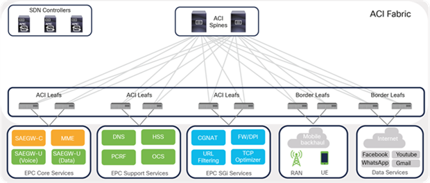
Cisco ACI solution for telco data centers
Let’s look at key benefits of Cisco ACI before going into details of implementation of these telco data center components with ACI.
1.1 Benefits of using Cisco ACI for telco data-center deployments
Cisco ACI provides the solution for high-performance, scalable, and distributed telco data centers with centralized management and consistent security and telemetry policies. Advanced technology features offered by the Cisco ACI solution addresses distinct and dynamic requirements for telco data centers. This includes intelligent service chaining for telco data center Gi-LAN Services blocks, management and visibility into core services hosted on virtualized and containerized environment, integrated security, and much more. The solution provides capability to move toward a cloud-based consumption model by offering programmable APIs for integrating with existing automation and orchestration tools.
Figure 4 highlights the key benefits offered by Cisco ACI specifically for telco data centers.
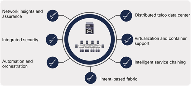
Cisco ACI fabric: key benefits for telco data centers
1.1.1 Distributed telco data centers
The Cisco ACI anywhere vision aligns with a distributed telco data centers model and offers solutions where services can be deployed across geographically separated locations and managed centrally with consistent policy control. The following primary solutions enable telco operators to deploy the services in any location in a distributed telco landscape and have them managed centrally with consistent policy control:
● Cisco ACI Multipod
● Cisco ACI Multisite
● Cisco ACI Remote Leaf
Cisco ACI architecture for 5G distributed telco data centers
The solutions allow secure communications between the services distributed across data centers and centralized management of all distributed data centers by providing full day-0 and day-1 automation and consistent day-1 policies, including end-to-end troubleshooting across all locations.
The Cisco ACI Remote Leaf features extend ACI policies to edge data centers or locations hosted for distributed 5G architecture. The remote leaf switches are managed from a Cisco Application Policy Infrastructure Controller (APIC) at the regional or central data center through functions that include zero-touch auto discovery, configuration deployment, and operations such as troubleshooting upgrades and downgrades.
The Cisco ACI Multipod solution interconnects multiple fabric pods (leaf and spines) deployed in multiple data centers locations and managed by a single APIC cluster. In the Cisco ACI Multisite solution, Cisco ACI Multi-Site Orchestrator (MSO) manages multiple fabrics (ACI sites) with a single point of management and consistent policy across geographically dispersed locations for 5G distributed architecture. Each site has independent APIC clusters and is completely isolated from other sites to offer a true disaster-recovery solution.
1.1.2 Virtualization and container support
Telco data centers demand support for all types of workloads, including bare-metal and virtualized workloads and containers. This brings in an additional layer of virtual networking offered by virtualized or cloud-native platforms that introduce a siloed approach to manage networking in distinct environments.
Cisco ACI provides single pane of management and visibility into the virtual networking of these mixed environment. Through Virtual Machine Manager (VMM) integration, Cisco APIC automates virtual network configurations and provides visibility of the endpoints deployed on multiple hypervisors and containers in a single view.
1.1.3 Intelligent service chaining
One of the most important use cases in telco data centers is service chaining. Mobile traffic in a data center needs to go through a chain of service devices (such as Carrier-Grade Network Address Translation [CGNAT], Deep Packet Inspection (DPI), TCP optimizers, etc.) before it can be forwarded to the Internet. In a traditional network, service chaining is configured on each node using Policy-Based Routing (PBR), multiple VRFs, and Access Control List (ACL) configurations.
Cisco ACI automates and provides scalability of service chaining through:
● Ease of configuration because service nodes are handled in a group rather than as individual nodes
● Easy expansion by simply adding additional devices in a group without changing the overall service policy configuration
● Automatic load balancing of traffic across service nodes
● Automatic symmetricity of traffic
● Health check of service nodes and automatic rebalancing of traffic across the remaining nodes
● Bypassing and reinsertion of the service group in a chain, based on threshold
Intelligent service chaining
1.1.4 Intent-based fabric
The traditional approach to network deployments involved a device-by-device approach for managing and monitoring the switches in the data center. With the Cisco ACI solution, day-0 fabric bring-up and day-1 fabric-wide provisioning are completely automated. To bring up a fabric, the fabric administrator just needs to provide on the APIC basic parameters such as a fabric subnet, an out-of-band management IP, and the APIC login credential. Once the fabric administrator registers the automatically discovered Cisco ACI leaf and spine switches, the APIC brings up the VXLAN fabric automatically and is ready for providing connectivity to external applications or endpoints.
Figure 7 lists the high-level procedure for bringing up the fabric using the simple steps shown.
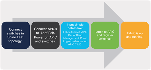
Fully automated provisioning of a Cisco ACI fabric
Network operators use APIC as a single pane of glass to operationalize the complete network. An intent-based approach allows the fabric administrator to define intent for application connectivity in simple terms; the APIC then translates and applies the intent or policies as actual networking language (configurations) that the leaf switches understand.
1.1.5 Automation and orchestration
Cisco ACI Open APIs offer a simpler approach to automate network or application provisioning by integrating with an existing automation tool in the telco data center. Automation efforts are significantly reduced by having the tool integrate with just one component—the APIC—instead of with each and every switch in the fabric.
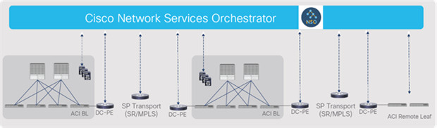
Cisco ACI can easily fit into an organization’s existing management and orchestration framework for end-to-end service-oriented automation. Customers can use the Cisco Network Services Orchestrator (NSO) for cross-domain orchestration across VIM, VNF, transport, and the data center network.
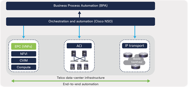
ACI fabric as part of service orchestration
1.1.6 Integrated security
Cisco ACI uses allow-list policies. By default, it does not allow communication between different Endpoint Groups (EPGs). An endpoint group is a collection of endpoints, such as servers, that have the same policy. An explicit contract is needed to allow communication between endpoint groups.
A user can choose to use microsegmentation based on security and application requirements. Cisco ACI provides one of most comprehensive microsegmentation solutions in the networking industry.
1.1.7 Cisco Network Insights and Cisco Network Assurance Engine
The scale and complexity of telco data-center environments keeps growing. To simplify network operations, Cisco provides the most comprehensive tools for network insights and assurance – Cisco Network Insights for Data Center and Cisco Network Assurance Engine (NAE) – to help users proactively monitor, find faults, troubleshoot, and get recommendations to resolve problems in the data center environment.
Figure 9 shows the day-2 operations architecture for a telco data center.
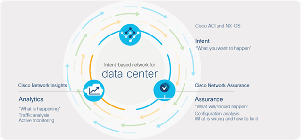
Day-2 operations tools for a telco data center
One of the challenges faced by operations is that current tools do not address the modern needs of a network. Multiple tools exist addressing siloed visibility cases and focused on gathering or collecting data. The data collected is left to the operations team to correlate and arrive at logical conclusions based on it. This approach is reactive and time consuming.
The Cisco Network Insights for Data Center application not only provides visibility into network health but also enables proactive and meaningful insights into your network. Using the hardware telemetry capabilities of Cisco Nexus® 9000 Series Switches, Network insights can provide detailed reports on data-plane issues such as higher latency, packet drops, and the reasons for packet drops. Cisco Network Insights inform users about the flow (for example, source IP, destination IP, L4 port, or protocols) that is causing the problem. This is immensely helpful to identify if a network is causing a problem for an application, and, if the network is the cause, then why and where the problem exists and how to fix it. The Application-Specific Integrated Circuits (ASICs) that are used have the capability to support hardware telemetry information by capturing full data-plane packet information at line rates.
Cisco Network Insights display network faults, events, and audit logs in a time-series fashion, thus providing historical states and information. Configuration changes, control-plane events and relevant data are collected and correlated using analytics (artificial intelligence [AI] and machine-learning [ML] algorithms) to present the operator with recommended remediation steps for a particular issue. It also helps in preventing unscheduled outages and lowers downtime for telco data centers by providing proactive notifications covering security advisories, critical bugs, end-of-life and end-of-support announcements and recommended software and hardware upgrades based on platforms, deployed software, and features. It also collects logs that can be attached to a Cisco Technical Assistance Center (TAC) case for faster troubleshooting.
Cisco Network Assurance Engine (NAE) ensures that the infrastructure is doing exactly what you intended it to do. It ensures that your changes and configurations are correct and consistent, and that the forwarding state has not drifted to a something undesirable, that the deployment and movement of VMs haven’t broken your reachability intent, or that your security policies are achieving segmentation goals according to intent. Using Network Assurance Engine, network operators can always remain compliant with business rules and can pass audits easily.
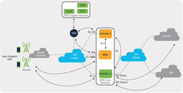
1.2 Evolved Packet Core (EPC) overview
An evolved packet core is part of the System Architecture Evolution (SAE) framework that is responsible for providing converged voice and data services for mobile subscribers on 3G or 4G Long-Term Evolution (LTE) standards. EPC forms the core network of the LTE system. Figure 10 shows the basic architecture of the EPC as provided in a 3GPP site. (3GPP [3rd Generation Partnership Project] is a standards organization that develops protocols for mobile telecommunications.)
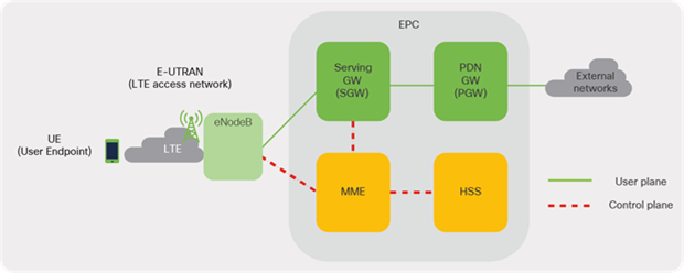
Basic architecture of EPC
Some of the key elements of the EPC solution can be categorized as elements of the control-plane responsible for carrying signaling and other traffic and others as elements of the user-plane that carry actual user data. Following is the list of elements of EPC:
● Cisco Mobility Management Entity (MME): The MME resides in the EPC control plane and manages session states, authentication, paging, mobility, roaming, and other bearer management functions.
● Cisco Serving Gateway (SGW): The SGW resides in the user plane where it forwards and routes packets to and from the eNodeB and packet data network gateway (PGW) (see below for a description). The SGW also serves as the local mobility anchor for inter-eNodeB (roaming) handover and mobility between 3GPP networks.
● Cisco Packet Data Network Gateway (PGW): The PGW acts as the interface between the LTE network and other packet data networks, such as the Internet or SIP-based IP Multimedia Subsystem (IMS) networks.
● Cisco Home Subscriber Server (HSS): The HSS is a database that contains user-related and subscriber-related information. It also provides other functions such as user authentication and authorization services.
For detailed information on EPC Core Services, see the 3GPP EPC architecture overview at the following URL: https://www.3gpp.org/technologies/keywords-acronyms/100-the-evolved-packet-core.
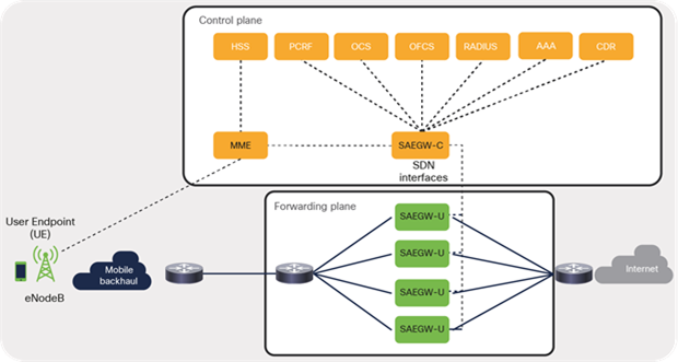
1.2.1 CUPS
As 3GPP standards have evolved, it was decided to separate the control-plane and data-plane aspects from the SGW and the PGW to make scaling independent. The right side of Figure 11 depicts the separation. This architecture offers numerous benefits for both businesses and operators since the components can be scaled independently on an as-needed basis and in real time. Most importantly, Control-plane User-Plane Separation (CUPS) ensures architectural readiness for 5G. The 5G core network will inherit the CUPS capability as defined in 3GPP Release 14.
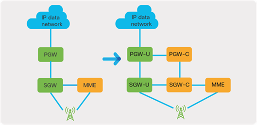
Control-plane User-Plane Separation (CUPS)
The CUPS solution offers multiple options to address various requirements of the business, as described below:
● Co-located CUPS: In this model, the control plane and user plane elements are centralized and hosted in the same data centers. This architecture provides the capability to scale the control and user plane independently and thus the flexibility to match an operator’s preferred pace of deployment.
● Remote CUPS: This model allows you to centralize elements of the control plane while distributing the user-plane instances to regional or edge locations that are closer to the users for better experiences, reduced latency, and lower utilization of transport bandwidth.
1.2.2 Cisco Network Functions Virtualization Infrastructure (NFVI) overview
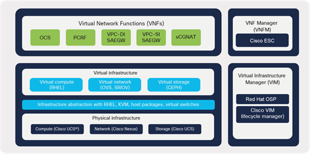
Cisco Network Functions Virtualization Infrastructure (NFVI) provides the virtualization layer and hardware environment where the Cisco EPC elements or functions are virtualized and hosted as Virtual Machines (VMs) or Virtual Network Functions (VNFs).
Figure 12 shows the key building blocks of the EPC solution and the components hosted as VNFs using the Cisco NFVI platform in central or regional data centers.
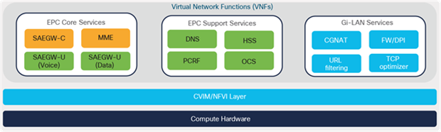
Cisco NFVI overview
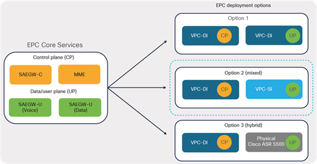
1.2.3 EPC deployments
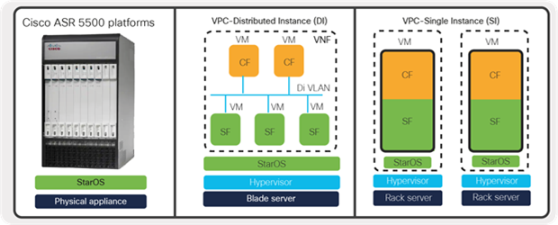
Cisco StarOS, a key component of the solution, is field-proven software, decoupled from hardware, that enables packet core functions to be deployed on hardware platforms such as Cisco® ASR 5500 series, as well as on virtualized platforms as Virtual Machines (VMs) or Virtual Network Functions (VNFs).
EPC deployment options
The EPC virtualized solution offers two different deployment models (VPC-DI [distributed instance] and VPC-SI [single instance]), to provide design flexibility depending on business requirements and needs.
1.2.4 VPC-Single Instance (VPC-SI)
VPC-Single Instance (VPC-SI) consolidates the operations of a physical Cisco ASR 5500 chassis running StarOS in a single Virtual Machine (VM) that can run on Commercial Off-The-Shelf (COTS) servers. Each VPC-SI VM operates as an independent StarOS instance, incorporating the management and session-processing capabilities of a physical chassis.
Below are some of the mobile packet core functions deployed using the VPC-SI model:
● LTE MME (Mobility Management Entity)
● PGW (PDN Gateway) and SGW (Serving Gateway)
● SAE-GW System Architecture Evolution Gateway: This is a combination of SGW and PGW nodes working in tandem to present as a single node.
Note: While there are other mobile functions (like small cell gateways and others) that can be deployed using these different approaches, this guide shall be focused on mobile packet core functions, especially based on System Architecture Evolution Gateway or SAEGW (SGW + PGW)
1.2.5 VPC-Distributed Instance (VPC-DI)
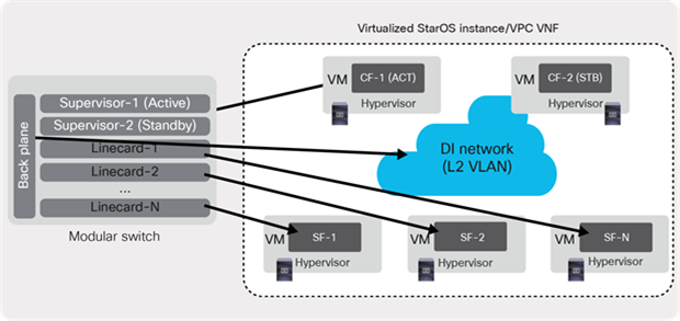
VPC-Distributed Instance (VPC-DI) distributes the virtualized StarOS beyond a single Virtual Machine (VM), enabling a group of Virtual Machines (VMs) to act as a single StarOS instance and single point of management.
The following are the major components of the VPC-DI instance:
● Control Function (CF): This is deployed as a VM and in redundant pairs for high availability, CF is responsible for controller tasks and performs functions similar to a supervisor module in a modular chassis platform.
● Service Function (SF): This provides service context and handles protocol signalling and session processing tasks. A VPC-DI instance can contain up to 30 VMs or more, depending on the VPC software release. This can be roughly equated to the use of line-card modules in a modular chassis platform.
● DI Network: This is a Layer 2 network or VLAN that enables communication between the CF and SF VMs. The DI network acts as a chassis backplane that interconnects the line-card modules (SF) to the supervisor modules (CF).
As depicted in Figure 14, the CF, SF, and DI Network work together to form a single virtual chassis and are managed as one VPC-DI instance.
EPC VPC-Distributed Instance
1.2.6 Deployment options
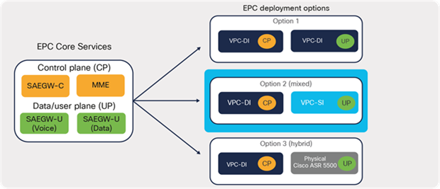
The Cisco Virtual Packet Core solution offers greater flexibility in EPC deployments. Depending on business requirements, multiple options exist and can be leveraged for EPC deployments. Figure 15 shows some of the possible options that are typically observed in real-world deployments. In option 1, elements of the control plane and user plane of the EPC leverage the VPC-DI approach for deployment. Option 2 involves the control plane leveraging VPC-DI while elements of the user-plane leverage the VPC-SI approach for deployments. The Hybrid CUPS option (3) allows operators to have a mix of both virtual and appliance-based solutions for EPC deployments. Operators can continue to use their existing appliance-based Cisco ASR 5500 series deployments by repurposing them to work as elements of the user-plane, while virtualizing elements of the control-plane. This approach helps operators leverage their existing investment and prepare for a future 5G-core network by using CUPS architecture.
EPC deployment approach
Note: This document uses EPC design references involving both VPC-DI and VPC-SI deployments with newly evolved CUPS architecture.
2 Bringing up telco cloud infrastructure
This section uses Cisco VIM (CVIM) as an example to host VNF. CVIM infrastructure comprises various management and cloud elements. Management elements include management or build nodes along with management switches. Cloud components include various nodes such as controller nodes, compute nodes, and storage nodes. Dedicated blades or compute nodes are allocated for each node type in a typical deployment. Cisco CVIM leverages OpenStack to build a telco cloud using pooled virtual resources (network, storage, and compute) where the VNFs are hosted.
Figure 16 depicts a high-level NFVI architecture. NFVI comprises all of the hardware and software components of a platform in which VNFs are deployed. CVIM controls and manages the NFVI’s compute, storage, and network resources.
Cisco NFVI architecture
2.1.1 NFVi network requirements
CVIM installation requires various networks (L2/L3) to be configured or pre-provisioned on a Cisco ACI fabric as part of the deployment prerequisites. As shown in Figure 17, the installer API and BMC/iLO/CIMC networks are dedicated to management purposes while other networks are used for the cloud components. For a connected installation, the management node might also require Internet connectivity to be able to download software from the Cisco VIM repository on the Internet. For offline installations without Internet connectivity, air-gapped installation approaches can be used with an additional staging server connected to a repository on the Internet, The first step is to get the software packages to USB from the staging server and connecting the USB to each pod management node. The second step is to ensure that the management node of each pod is connected to the central staging server.
For cloud components, the ACI fabric can be configured to provide gateway services for required networks (L3), such as provider, management/provisioning, external, cloud API, etc. Provider networks or VLAN ranges are often used for real VNF traffic. These networks carry data traffic from VMs or VNFs in and out of the CVIM environment. Using a cloud API network, clients connect to the API network to interface with OpenStack APIs for managing or using the NFVI. Management and provisioning networks are used for the Preboot Execution Environment (PXE) booting server during bare-metal installations and OpenStack inter-service communications. For networks requiring no gateway services (for example, tenant networks), the ACI fabric can be configured to provide Layer 2 constructs only. Tenant networks are used to carry VM-to-VM traffic within CVIM environments and are local to NFVI.
Figure 17 shows the networks that must be made available on the network infrastructure for Cisco VIM deployments.
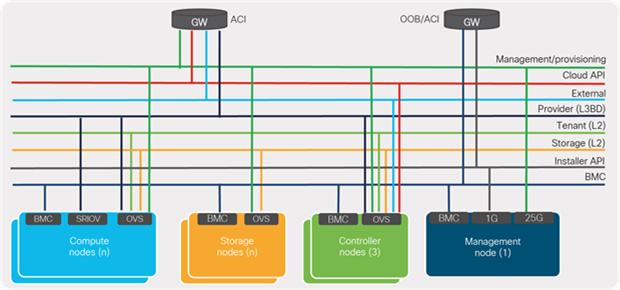
NFVI network requirements
2.1.2 Physical connectivity
Cisco ACI fabric provides physical connectivity to the various interfaces of CVIM nodes that are used for carrying different types of traffic. Typically, the mLOM ports or ports used by Open vSwitch (OVS) in OpenStack are used for carrying the various networks depicted in Figure 17, except for the provider and BMC management networks. These ports are typically dual-attached to the fabric leaf switches in their respective racks and configured in virtual Port-Channel (vPC), providing link- and path-level redundancy. The SRIOV ports offer high-bandwidth interfaces (10/25/40G) that are used for carrying provider VLANs or data traffic from the VNFs hosted in NFVI. SRIOV ports are dual-attached to leaf switches but generally act as individual interfaces carrying routed traffic, because, from a compute perspective, bundle interface is not supported on SRIOV ports. The management or build nodes use the mLOM interfaces for carrying provisioning traffic (PXE boot and installation) and dedicated 1G ports for carrying the installer API network for the administrator to SSH to the management node and carryout operations.
Depending on the Out-Of-Band (OOB) management design, a BMC/iLO/CIMC port can be connected to an ACI fabric or to dedicated management switches.
Figure 18 shows the typical physical connectivity design between an ACI fabric and the various nodes of a CVIM infrastructure.
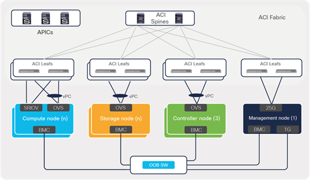
ACI physical connectivity to cloud infrastructure
2.1.3 Logical connectivity
Cisco Application Policy Infrastructure Controllers (APICs) provide a single pane of glass solution for managing and monitoring an ACI fabric consisting of multiple leaf and spine switches. ACI logical constructs or intents are defined by the fabric administrator on APICs, which push networking, operational, and troubleshooting policies to leaf and spine switches, based on the location of VNFs or applications.
From the perspective of logical connectivity, typically the networks required for a Cisco VIM installation are hosted under the preconfigured management (mgmt) tenant. These networks can be statically configured on APIC using constructs such as bridge domains, endpoint groups (EPGs), and contracts.
Figure 19 shows the ACI constructs and EPG bindings to the leaf switch ports that are required for establishing connectivity between various nodes when bringing up a CVIM cloud.
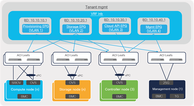
ACI logical connectivity to cloud infrastructure
After completing the CVIM installation, the telco cloud administrator can start instantiating EPC functions as VNFs. The following sections in this guide cover the fabric design for establishing connectivity to various functions or blocks that are part of EPC services.
The block of Cisco ACI EPC Core Services in the telco data-center architecture consists of key packet core functions such as Cisco Mobility Management Entity (MME), Cisco Serving Gateway (SGW), and Cisco Packet Data Network Gateway (PGW), which are responsible for providing converged voice and data services for mobile subscribers. These elements of the EPC Core Services participate in traffic-forwarding functions and peer with Cisco ACI fabric over L3 external or L3Out interfaces.
This section focuses on how these requirements can be addressed and simplified using Cisco ACI for telco data-center environments. It also explains some of the key traffic-flow requirements and design considerations for connecting EPC Core Services to a Cisco ACI fabric.
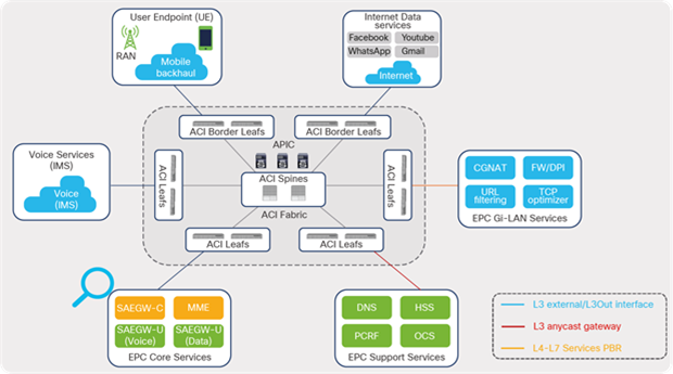
ACI fabric EPC Core connectivity
Note: The examples used in this discussion feature a colocated CUPS architecture where the control-plane and user-plane functions of the EPC Core Services are centralized in central or regional telco data centers.
3.1 VNF networking requirements
Typically, EPC Core Services deployments can include multiple virtual instances and can spread across multiple racks, depending on capacity and throughput requirements. This brings unique requirements to the design in terms of routing protocol peering across multiple switches and handling VNF mobility and traffic distribution to the multiple instances. In a traditional enterprise workload, VMs require the distributed gateway function to support VM mobility. In a telco cloud, a VNF requires distributed routing functionality along with the distributed gateway. An ACI fabric needs additional Equal-Cost Multipath Routing (ECMP), faster convergence, and routing enhancements to support these. The following are some key requirements of VNFs specific to telco workloads:
● Virtual Evolved Packet Core (vEPC) VNFs distributed across multiple racks and leaf nodes
● Flexibility to deploy VNFs based on capacity in racks, servers, etc.
● ECMP support within the ACI fabric toward leaf switches connected to VNFs
● ECMP from each leaf to all VNFs hosted across multiple racks. ECMP must be supported, not just to directly connected VNFs, but also to VNFs that are reachable through the Layer 3 fabric. If ECMP is only supported to directly connected VNFs, then all leaf switches must have an equal number of VNFs connected to it; otherwise, VNFs will receive unequal amounts of traffic, resulting in packet loss. Connecting equal amounts of VNFs to all leafs may not be possible for many service providers; also, doing so is against the basic principle of allowing any VNFs to be placed anywhere.
● Routing and Bidirectional Forwarding Detection (BFD) over the ACI fabric, since each VNF needs to do peering, not just with the leaf switches that are connected to it, but with other leaf switches as well. This peering across the fabric is required to support ECMP, faster convergence, and the capability to move VNFs across the fabric.
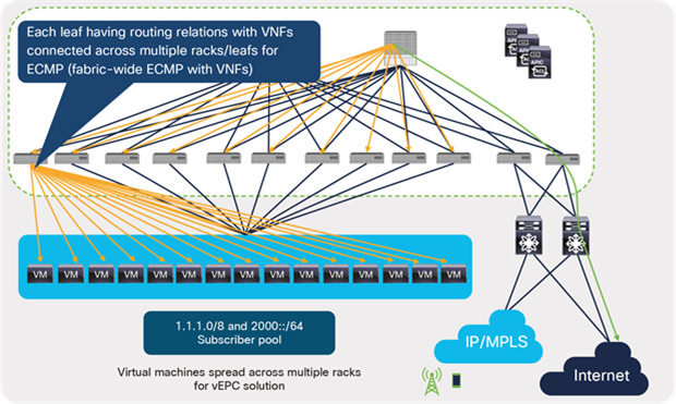
vEPC traffic-forwarding requirements
The ACI fabric supports all of the above requirements and has been deployed with different vendors’ EPC solutions. Addressing these requirements using traditional approaches requires complex configurations (such as a large Layer 2 domain and spanning tree) and challenges in operations.
3.2 Traffic-flow requirements
As depicted in Figure 22, MME/SAEGW-C is mainly responsible for handling signaling traffic in the packet core, including other support services such as user-authentication, authorization (HSS), and policy-enforcement and flow-based charging (also called policy and charging rules function, or PCRF), to name a few. The user or data-plane instances (SAEGW-U) in the architecture is responsible for transporting IP data traffic from User Endpoints (UEs) such as mobile handsets and external networks such as the Internet. A SAEGW node is a combination of SGW and PGW nodes working in tandem to present as a single node.
EPC Core architecture
Each of the functions or elements in the control and user plane uses various interfaces, as defined in 3GPP standards, when communicating with other elements that are part of the architecture. Figure 23 depicts some of the key interfaces involved in a mobile packet core network.
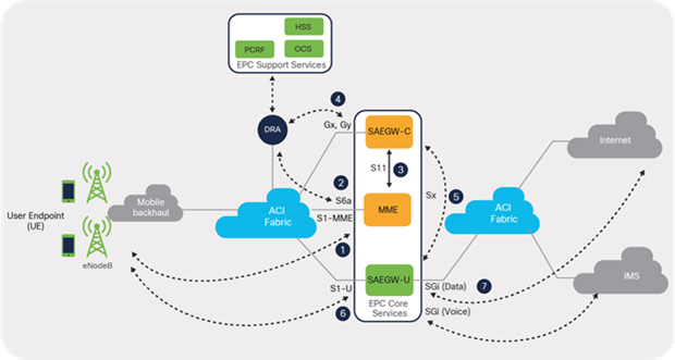
EPC Core interfaces
Table 1 lists key EPC Core interfaces with a brief description and the mapping to traffic type of each.
Table 1. EPC Core interfaces
| ID |
Interface |
Description |
Traffic type |
| 1 |
S1-MME interface |
Signaling interface on MME, used for signaling functions during the initial attachment procedure when a user endpoint or mobile handset tries to register to the radio network |
Control |
| 2 |
S6a interface |
Interface used between MME and HSS for user-endpoint authentication during the initial attachment procedure. HSS is a user database server that performs authentication and authorization of the user. |
Control |
| 3 |
S11 interface |
Interface between MME and SAEGW-C (SGW), used for creating and deleting sessions, etc. On user authentication, MME triggers a user session creation request to SAEGW-C using the S11 Interface. |
Control |
| 4 |
Gx/Gy interface |
Interface between SAEGW-C and PCRF to handle policy, and Interface between SAEGW-C Online Charging System (OCS) systems in order to handle charging rules for mobile subscribers |
Control |
| 5 |
Sx interface |
Interface for communication between SAEGW-C and SAEGW-U. On receiving a session creation request, SAEGW-C selects a forwarding engine or SAEGW-U for creating an Sx session for a user-endpoint/PDN connection. |
Control |
| 6 |
S1U interface |
Interface between eNodeB and SAEGW-U (SGW) used for carrying Internet data traffic from a user endpoint over a GTP-U tunnel |
Data |
| 7 |
SGi interface |
Interface between SAEGW-U (PGW) and the Internet for carrying Internet data traffic from a user endpoint or mobile subscriber |
Data |
3.2.1 Traffic classification
Based on the communication requirements between various EPC elements and interfaces, the traffic flows from a Cisco ACI fabric perspective can be broadly categorized as follows:
● EPC Core to Radio Access Network (RAN)
● Intra-Core communications
● EPC Core to EPC Support Services communications
● EPC Core to IP Multimedia Services (IMS) voice / Internet communications
3.2.1.1 EPC Core to Radio Access Network (RAN)
North-south communication includes control-plane and data-plane forwarding traffic (signaling, voice, and data traffic) between eNodeBs and EPC Core Services components.
Table 2 lists the EPC components and interfaces involved in these communications.
Table 2. EPC interfaces facing radio access
| EPC component |
Interfaces |
Block (components) |
| MME |
S1-MME |
Mobile backhaul (eNodeB) |
| SAEGW-U (data) |
S1-U |
Mobile backhaul (eNodeB) |
| SAEGW-U (voice) |
S1-U |
Mobile backhaul (eNodeB) |
Figure 24 illustrates communications between EPC Core Services and a mobile or radio access block in a telco data-center landscape.
EPC traffic classification: north-south (radio access)
3.2.1.2 Intra-Core communications
This section deals with east-west communications that take place between the EPC Core Services functions, such as MME and SAEGW-C/U. The traffic involved is mostly control-plane traffic, and the communication takes place over various interfaces depending on the component used.
Table 3 lists the EPC elements and interfaces involved in these communications.
Table 3. EPC interfaces: intra-Core
| EPC elements |
Interfaces |
Block (components) |
| MME |
S10, S11, DNS |
Within EPC core |
| SAEGW-C |
S5-SGW, S5-PGW, Sx, S11, S2BC, S2AC |
Within EPC core |
| SAEGW-U (data) |
S5-SGW, S5-PGW, Sx |
Within EPC core between SGW and PGW |
| SAEGW-U (voice) |
S5-SGW, S5-PGW, Sx |
Within EPC core between SGW and PGW |
Figure 25 illustrates communication between EPC Core Service functions.
EPC traffic classification: east-west (intra-Core)
3.2.1.3 EPC Core to Support Services
This section deals with east-west communications that take place between EPC Core Services and EPC Support Service functions such as HSS, PCRF, etc. For the most part, the traffic involved is signaling traffic (user-authentication, policy control, and charging functions), and communication happens over various interfaces, depending on the functions.
● Elements of EPC Support Services are deployed as Virtual Machines (VMs) to which the Cisco ACI fabric provides anycast gateway functions. This is covered in detail under the section “EPC Support Services” in this guide.
Table 4 lists the elements of EPC and interfaces involved in these communications.
Table 4. EPC interfaces: EPC Support Services
| EPC elements |
Interfaces |
Block (components) |
| MME |
S6a, S13, SGs, Sbc, SLg, SLs |
EPC Core to EPC Support Services |
| SAEGW-C |
Ga, Gx, Gy, S6b |
EPC Core to EPC Support Services |
Figure 26 illustrates traffic flows between EPC Core Services and EPC Support Services in a telco data-center landscape.
EPC traffic classification: east-west (EPC Support Services)
3.2.1.4 EPC Core to Internet data/voice
This section covers north-south communications that take place between an SAEGW-U SGi interface and Internet destinations for data traffic and IMS destinations for voice traffic.
Table 5 lists the EPC elements and interfaces involved in these communications.
Table 5. EPC interfaces facing Internet
| EPC elements |
Interfaces |
Block (components) |
| SAEGW-U (data) |
SGi |
EPC Core to Internet data |
| SAEGW-U (voice) |
SGi |
EPC Core to IMS voice |
Figure 27 illustrates communication flow between EPC Core Services and Internet data and voice destinations in a telco data-center landscape.

EPC traffic classification: north-south (Internet)
It is to be noted that the S1U interface is the point of interconnect between the radio-side (eNodeB) and the EPC. The SGi interface is the point of interconnect between the EPC and an external network such as the Internet. As depicted in Figure 28, the data traffic from the user endpoint can be intelligently steered to a Gi-LAN Services block before reaching the Internet for value-added and security functions. This is covered in detail under the section “Gi-LAN Services Design” in this guide.
Cisco ACI fabric: intelligent traffic steering
3.2.2 IPv4/IPv6/dual-stack support
The decision to go with an IPv4, IPv6, or dual-stack deployment in an ACI fabric is dependent on the EPC solution requirements. In order to make a network dual-stack, mobile subscribers needs to get both IPv4 and IPv6 addresses. In addition, a mobile client source (IPv4/IPv6) needs to be able to reach both IPv4 and IPv6 internet address destinations, since there are websites on the Internet that do not yet support IPv6. In order to reach IPv4 destinations on the Internet, NAT64 and DNS64 complementary transition technologies help provide access.
An ACI fabric supports IPv4, IPv6, or dual-stack deployments and enabling dual-stack on L3 external interfaces, and the same VLAN can be used for both IPv4 and IPv6 interfaces.
3.2.3 EPC service addresses
Service loopback addresses and subscriber pool addresses configured on elements of EPC Core Services are some of the key address types that require reachability from different places in a telco data-center landscape.
In EPC, loopback interfaces are defined on elements of the EPC Core Services for each type of service interface (S1-MME, S1U, etc.) that it hosts. These loopback addresses are also called service loopback addresses. These interfaces are used for carrying various control and data plane traffic; therefore, the underlying network infrastructure must ensure reachability to these addresses or prefixes. Routing protocols employed in this solution need to ensure reachability of the service loopback addresses, especially between the eNodeBs in radio access networks and EPC Core Services in a telco data center.
Mobile subscribers attaching to an LTE network are assigned IPv4/IPv6/dual-stack addresses from the subscriber pool range. The SAEGW-C element is responsible for assigning the address from its subscriber pool range during the initial user-endpoint attachment procedure. The user-endpoint uses the IP address for accessing Internet data; therefore, the underlying network infrastructure must ensure reachability to the address range from the perimeter Internet layer for the return traffic along the path toward the user endpoint.
3.3 Multitenancy and VRFs
A key requirement when deploying an EPC solution is segregating traffic; of particular importance, segregating management, radio, and data traffic from each other for the sake of security and management. A typical telco data-center solution includes a multi-VRF design segregating various traffic types. Cisco ACI provides a built-in multitenancy capability to segregate traffic based on tenants in addition to VRFs. The tenants provide administrative boundaries where all logical configurations, including operational and troubleshooting policies, can be defined and controlled at a tenant level. Within a tenant, one or more VRFs or contexts can be defined to provide routing segregation for the different traffic types.
Figure 29 shows the multitenancy and VRF design used in this discussion.
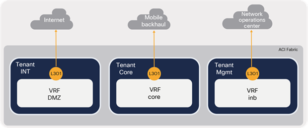
Multitenancy and VRFs
When planning the design of a telco data-center VRF, it is important to consider what all elements that are part of EPC Core Services (MME and SAEGW-C/U) are covered in the deployment and how the VRF segregation is planned at the element level. Because It is not necessary that all elements that are part of EPC Core Services are centralized and hosted in a single data center. Certain deployments can include control-plane elements centralized and hosted in a single location while data-plane elements (in this case, SAEGW-U) are distributed and hosted in a remote site or in regional sites close to the users. Therefore, it is important to consider the EPC elements that are involved and the deployment model used while designing VRF and routing for an EPC solution.
When mapping VRFs between EPC elements and an ACI fabric, there can be one-to-one mapping or many-to-one mapping, depending on the overall design, including the perimeter and the transport layer in the landscape.
Table 6 lists the many-to-one mapping of VRFs between EPC Core Services and an ACI fabric used in this discussion.
Table 6. ACI fabric: EPC VRF mapping
| EPC VNF |
EPC VRFs |
Purpose |
ACI tenant/VRF |
| MME |
Local |
Operations and management |
mgmt/inb |
| ACCESS |
Connection toward eNodeB (S1-MME) |
Core/Core |
|
| SIGNAL |
Connection toward EPC Supporting Services |
||
| CORE |
Toward other VNFs (SAEGW-C/U, DNS) |
||
| SAEGW-C |
Local |
Operations and management |
mgmt/inb |
| CORE |
Connections toward other VNFs/components:
● Between SGWs and PGWs (S5,S8)
● Connection toward MME(S11)
● Connection toward SAEGW-U (Sx)
|
Core/Core |
|
| SIGNAL |
Connection toward PCRF, OCS, mediation server, and AAA |
||
| SGI |
Context has the IP pools for the data APN. |
||
| SAEGW-U |
Local |
Operations and management |
mgmt/inb |
| CORE |
Connections toward mobile backhaul and other VNFs:
● Toward eNodeB (S1-U)
● Toward SGW-U (S5/S8)
|
Core/Core |
|
| SGi |
Connection towards to IMS/Internet |
Internet/DMZ |
Figure 30 depicts the many-to-one mapping of VRFs between an ACI fabric and EPC Core Service elements.
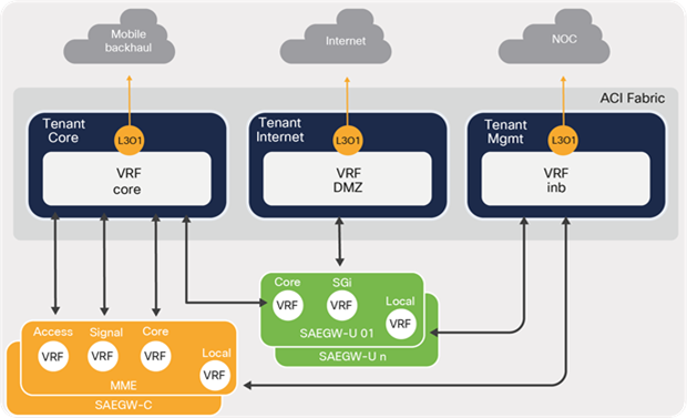
ACI and EPC VRF mapping
3.4 L3 external requirements
When planning for enabling logical connectivity towards EPC Core Services as depicted in Figure 31, one of the key design aspects is determining the number of L3 External interfaces required on an ACI fabric.
EPC Core interfaces
As discussed in the section on “Traffic Classification,” the various interfaces can be broadly grouped into four categories based on traffic type. An L3 external or L3Out can be assigned to each traffic type as listed in Table 7.
Table 7. Traffic Type to L3 external mapping
| Traffic type |
ACI L3 external |
| EPC Core to mobile / radio access (toward eNodeB) |
EPC S1-L3Out |
| Intra-Core |
EPC CP-L3Out |
| EPC Core to EPC Support Services |
EPC Signal-L3Out |
| EPC Core to Internet |
EPC SGi-L3Out |
Figure 32 shows the required L3 external or L3Outs for enabling L3 connectivity for the four communication types. Each L3Out can peer with multiple elements of EPC Core Services depending on the block that the elements connect to in the landscape.
Mapping L3 external to EPC interfaces
Table 8 provides the mapping between ACI fabric L3 external toward EPC interfaces used for this discussion.
Table 8. ACI L3 external to EPC interface mapping
| EPC VNF |
EPC interfaces |
ACI fabric (L3Out) |
ACI fabric (tenant/VRF) |
| MME VNF |
● S10
● S11
● DNS
|
EPC CP-L3Out |
Core/Core |
| SAEGW-C VNF |
● S5-SGW, S5-PGW
● Sx, S11
● S2BC, S2AC
|
||
| SAEGW-U VNF |
● S5-SGW, S5-PGW
● Sx
|
||
| MME VNF |
● S6a, S13,
● SGs, Sbc, SLg, SLs
|
EPC Signal-L3Out |
|
| SAEGW-C VNF |
● Ga, Gx, Gy
● S6b
|
||
| MME VNF |
● S1-MME
|
EPC S1-L3Out |
|
| SAEGW-U VNF |
● S1-U
|
||
| SAEGW-U VNF |
● SGi
|
SGi-L3Out |
Internet/DMZ |
3.5 Design considerations
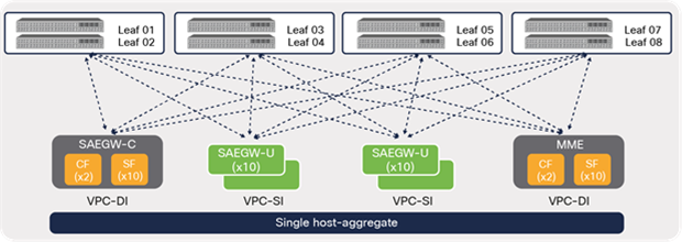
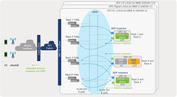
This section covers some of the key design considerations and guidelines for L3 external deployment toward EPC Core Services. For this discussion, EPC deployment option 2 is chosen where elements of the control plane (MME and SAEGW-C) are deployed using a VPC-DI approach and elements of the user plane (SAEGW-U) using a VPC-SI approach.
EPC deployment options
When designing L3 external connectivity toward EPC Core Service components, some of the key factors that need to be considered are VNF placement, EPC deployment models, and host-aggregate design. These play an important role in maintaining routing efficiency by reducing the number of routing peers and ensure seamless connectivity when a VM or VNF moves from one compute node to another across different racks within a CVIM pod.
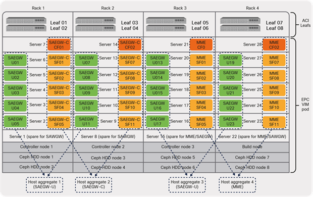
Figure 34 shows the EPC Core Services VNF placement used in this discussion.
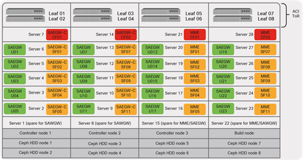
EPC Core VNF placement
Figure 34 has four racks. Each rack includes two ACI leaf switches and seven compute nodes, including a spare hosting different VNFs that are part of the EPC Core deployment. ACI leaf switches provide physical connectivity to the compute servers installed in the rack. SRIOV ports on the compute nodes are used for carrying the provider or data VLANs over high-bandwidth links (10/25/40G).
EPC control plane elements (MME and SAEGW-C VNF) in the solution leverage 2 x CF (Control Function) and 10 x SF (Service Function) Virtual Machines (VMs). The control plane elements share the compute node along with the data plane element SAEGW-U (x20 instances) to avoid multi-VNF failures of the same type. One compute node in each rack is dedicated as a spare; it is used in the event a compute node in the rack fails to host the VNFs.
3.5.1 Host aggregates
Host aggregates play a crucial role in planning a number of the routing protocol peerings required from MME and SAEGW-C/U toward ACI leaf switches. It is a term used in a VIM solution (OpenStack) that allows segregating and grouping the compute nodes into multiple availability zones. The compute nodes assigned to each type of element are grouped into availability zones or into host aggregates; in the latter case, they restrict VNF or VM mobility to the compute nodes that are part of the host aggregate.
3.5.1.1 Single host-aggregate
A single host-aggregate means that all compute nodes in all four racks are part of the same availability zone, as shown in Figure 35. This deployment allows any VM or VNF to move to any compute nodes across the racks. At the same time, this brings a unique challenge in terms of enabling routing protocol peering over the ACI fabric due to mobility requirements.
CVIM host aggregate (default: single)
A Cisco ACI fabric provides the capability to perform routing protocol peering over the fabric. The ACI fabric enables this through an internal BD function that is created per SVI interface defined under L3 external or L3Out. As shown in Figure 36, even though the compute nodes hosting the SAEGW-U VNF is physically connected to the local leaf switches in the rack, logically the peering is achieved over the ACI fabric using the internal BD function. If the VNF moves from rack 1 to a compute node in rack 4, it can still maintain L3 connectivity and serve traffic without any disruption.
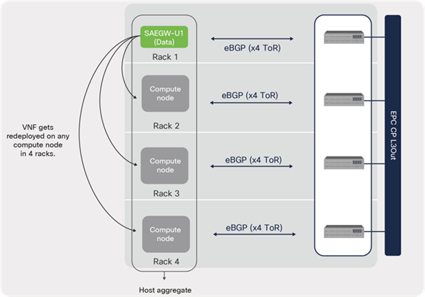
EPC VNF peering during mobility
A single host-aggregate environment requires full-mesh peering from every EPC Core element to all of the leaf switches in a pod to ensure connectivity. However, the scale of routing protocol peering can be reduced drastically using a multiple host-aggregate deployment, which is discussed next.
EPC VNF peering (single host-aggregate)
3.5.1.2 Multiple host-aggregates
For multiple host-aggregate deployments, where each EPC VNF type or element is grouped into its own host aggregate or group, the routing protocol peering requirement from a VNF can be reduced to only the leaf switches where the compute nodes that are part of a given host aggregate are located.
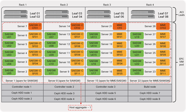
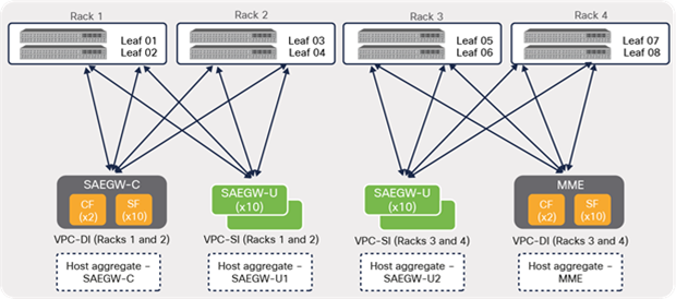
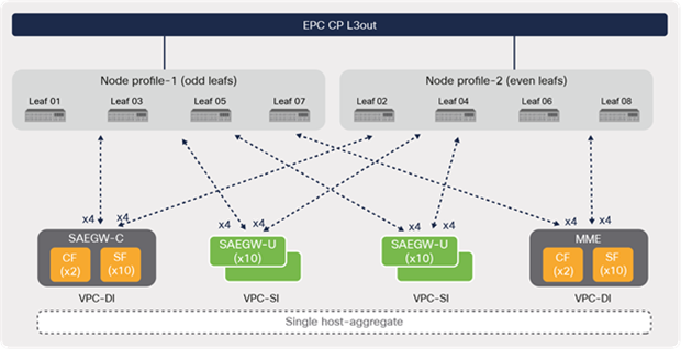
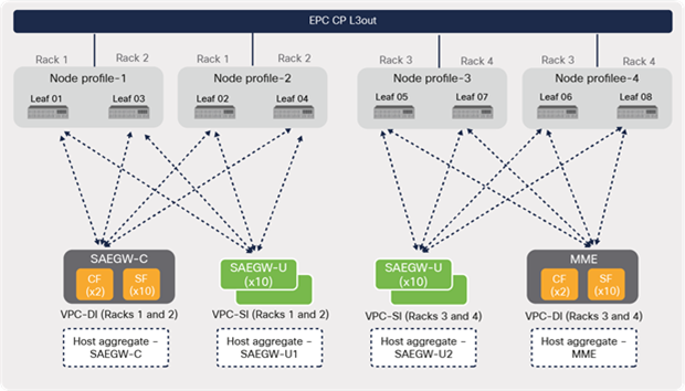
Figure 38 depicts multiple host-aggregates that are used in this discussion, where MME and SAEGW-C VNFs are grouped into their own host aggregates (2 and 4), while SAEGW-Us are grouped into two host aggregates (1 and 3).
CVIM host aggregate (multiple)
As shown in Figure 39, using a multiple host-aggregate, the routing protocol peering is minimized by having peering only to the leaf switches where the compute nodes that are part of the host aggregate reside.
EPC VNF peering (multiple host-aggregates)
In addition to host aggregates, for VPC-SI deployments leveraging the Inter-Chassis Service Recovery (ICSR) feature, route peering can be limited to the local leaf switches in a given rack, as shown in Figure 40.
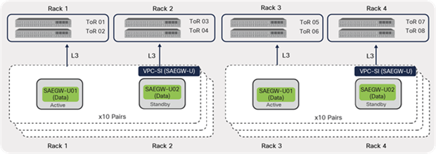
EPC VNF peering (VPC-SI ICSR)
3.5.2 Inter-Chassis Service Recovery (ICSR)
Inter-Chassis Service Recovery (ICSR) provides high availability and redundancy to elements of EPC or VNFs that are deployed using the VPC-SI model. This feature employs a session recovery protocol for exchanging periodic “hello” messages between the active and standby instances and shares current route modifier values. Both active and standby instances in the ICSR configuration peer with the ACI fabric.
For example, in Figure 41, active and standby instances are deployed (typically) on different compute nodes and racks. Both instances maintain L3 peering with only the local TOR switches. The active instances have higher priority and advertise the service loopbacks toward ACI leaf switches. During ICSR switchover, the standby instance takes over as active and starts advertising the routes toward ACI.
This design eliminates the need for having a routing protocol peering configuration on SAEGW-U with all of the leaf switches across the racks. With the ICSR feature, each VNF acts as an independent unit with a redundant or standby unit. Therefore, the VNF routing relationship can be limited to a local leaf switch pair. If VNF mobility is required, then the VNF needs to peer with all of the leafs where mobility is required, and the host aggregate concept can be used.
ACI peering with VPC-SI instances using ICSR
3.5.3 L3 external interface
Since the core elements of EPC are virtualized and hosted as VNFs, a Switched Virtual Interface (SVI) provides greater flexibility in the design by allowing L2 connectivity between all of the compute nodes for VNF mobility. VNFs can also have routing relationships with the ACI leaf switches over the SVI interface.
Single Root I/O Virtualization (SRIOV) interfaces on compute nodes are typically used for carrying the provider or data traffic. In this case, for carrying routed VLAN traffic from EPC VNFs, SRIOV allows for partitioning of the physical adapter into multiple virtual interfaces. It offers the enhanced performance by bypassing the virtual switch layer and presenting the virtual interface directly to the VNFs. By doing so, the I/O overhead involved in the virtual switch layer (OVS) is reduced and offers enhanced performance close to nonvirtualized environments.
A typical EPC design involves each VNF hosting two VLAN interfaces to connect to the ACI fabric leaf switches to provide high availability and path redundancy in case of failures. Each L3 external or L3Out used in the design leverages two VLAN SVIs, split between odd and even leaf switches, to connect to the EPC elements, as depicted in Figure 42.
L3 external interface for EPC peering
3.5.4 L3Out node profiles
When planning for L3 external configurations to EPC Core Services, it is important to consider whether to go with two node profiles (odd and even leaf switches) or multiple or individual node profiles per leaf switch. The decision is also dependent on whether the design uses a single or multiple host-aggregate design.
The L3 external node profile configuration in Cisco ACI allows the designer to define multiple leaf nodes under a single node profile. Any configuration defined under the node profile (Border Gateway Protocol [BGP] peering, for example) is applied to all the leaf nodes configured under the profile. This simplifies the configuration effort significantly, especially for large-scale deployments.
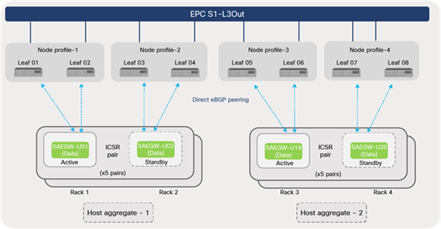
Single-host-aggregate deployments can benefit using a two node-profile option, because all the leaf switches are required to have routing protocol peering with EPC Core Elements, as depicted in Figure 43.
L3 external node profiles (single host aggregate)
For deployments involving multiple host-aggregates, configuring node profile based on host aggregates provides better flexibility in the configuration. This option allows a user to configure routing protocol peering only on the required leaf nodes based on host-aggregate configurations, as shown in Figure 44.
L3 external node profiles (multiple host-aggregates)
It is to be noted that, as on Cisco ACI Release 5.0, the maximum number of border leaf supported per L3Out is 12; therefore, the solution can scale up to six racks (two leafs per rack) without adding additional L3Outs to the design. If the solution needs to scale beyond six racks as part of an expansion of EPC capacity, then an additional L3Out needs to be considered in the design.
3.5.5 ECMP
For an appliance-based packet-core solution such as a Cisco ASR 5500 chassis, ports from multiple Service-Function (SF) or data line cards can be bundled into an L3 port channel. Traffic distribution is ensured using a port-channel hashing method, as depicted in Figure 45.
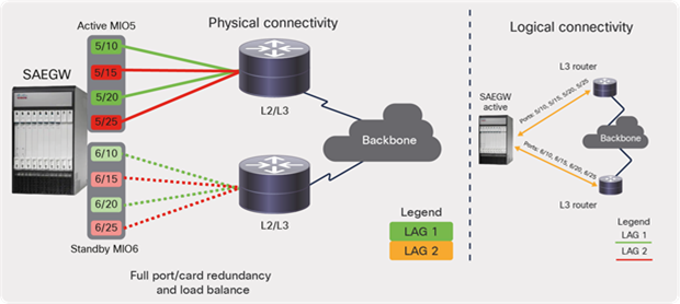
EPC traffic distribution (physical appliance)
The above method does not apply for an EPC virtualized solution, especially for instances leveraging a VPC-DI approach. EPC Core Service elements deployed using a VPC-SI approach are treated as independent instances and participate in traffic forwarding. However, deployments leveraging a VPC-DI model, where multiple VMs together act as a single VNF, require additional considerations, especially in terms of traffic distribution to multiple-Service-Function (SF) VMs.
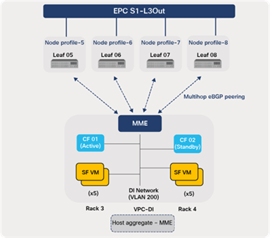
In Cisco ACI, traffic distribution to multiple SF VMs is achieved using an ECMP feature offered by routing protocols (static routing or dynamic OSPF), along with multihop eBGP. The Cisco ACI fabric supports up to 64-way ECMP for OSPF, BGP, and static routes. Note that, before deciding on the routing protocol to be used for the design, the EPC vendor’s requirements for supporting the chosen protocol need to be taken into consideration.
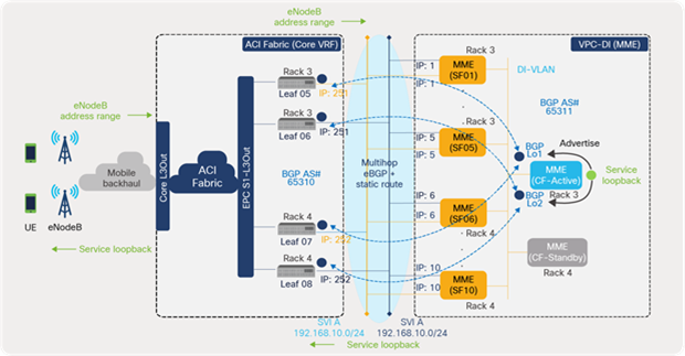
In this guide, let’s take the example of an EPC Core element MME deployed across two racks (3 and 4) using a VPC-DI approach with Control Function (CF) (x2), SF (x10), and a DI-network (L2), as depicted in Figure 46. Cisco ACI leaf switches peer with the CF VMs over eBGP, using loopback addresses. Static routes are configured on each leaf destined to BGP loopback addresses on MME with next hops as SF VM SVI addresses. MME advertises the service loopback address to ACI, which in turn advertises to mobile backhaul.
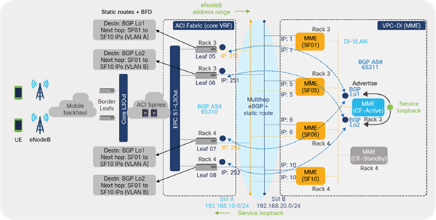
ACI fabric to MME ECMP configuration
Figure 47 below illustrates the ECMP forwarding based on the above configuration in place. Traffic from eNodeBs is always destined to the service loopback addresses configured on MME. When the packet reaches the ACI leaf switch, a routing lookup is done on the service loopback address, which results in BGP loopback address of MME (SAW-GW-C CF) as a next hop. A recursive lookup on the BGP loopback address results in 10 ECMP next-hops that are SVI addresses of the 10 SF VMs. An ACI leaf switch does ECMP forwarding to all of the 10 SF VMs, ensuring traffic distribution to all of the SF VMs.
Since Cisco ACI supports up to 64-way ECMP, up to 64 SFs can be deployed, distributed across the fabric.
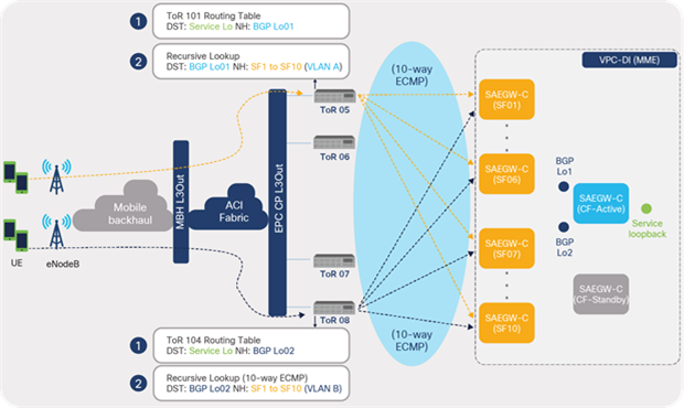
ACI fabric ECMP forwarding
3.5.6 Resiliency and convergence
For EPC deployments leveraging VPC-DI, Bidirectional Forwarding Detection (BFD) must be enabled on static routes to avoid a traffic black-hole during SF VM failure cases. As mentioned in the previous section, traffic distribution to SF VMs (x10) is achieved using the static route ECMP method. With BFD enabled on a static route, when an SF VM or compute node fails due to an unplanned event, the ACI fabric leaf switches can detect the failure quickly and remove the failed path from its forwarding table. The traffic is distributed across the remaining paths toward the available SF VMs.
For VPC-SI deployments that use eBGP peering with ACI leaf switches, BFD must be enabled on BGP protocol for improving convergence during failure scenarios. Services such as voice in telco data centers are sensitive and demand extremely low convergence from the underlying network during failure scenarios. Routing convergence is critical especially for user-plane instances serving voice traffic to avoid dropping voice connections. Convergence can be improved by leveraging BFD and tuning protocol timers in the fabric. Cisco ACI fabric offers convergence less than 200 msecs during any failures in the fabric, access connectivity, or external connectivity; this avoids any application outage during network link or node failures, upgrades, or downgrades.
Starting with Cisco ACI Release 5.0, ACI supports BFD multihop for BGP protocol. Therefore, if BGP neighborship is built over loopback interfaces instead of directly connected links, BFD multihop can detect BGP peer failure faster using BFD timers, compared to depending on default BGP timers.
With BFD control-plane independent C-bit support in Cisco ACI Release 5.0, ACI listens to C-bit advertisement from a Graceful Restart (GR)—capable peer and allows BGP to remove the next hop based on BFD, instead of waiting for the graceful restart timer to expire. If BFD C-bit is set to 1 by a GR-capable peer, indicating that it is control-plane independent, BFD sessions stay up during any control-plane failure. BGP on ACI does not bring down the routes and continues to forward the traffic. If C-bit is set to 0 by the peer, indicating that it shares the same fate as the control plane, BFD sessions are brought down and BGP routes are removed. This feature allows ACI to provide fast convergence without having to tweak BGP timers and to resume traffic forwarding over an alternate path.
3.6 Fabric internal routing
ACI fabric internal routing ensures external-route (for example, mobile backhaul and Internet) reachability and availability on the required leaf switches within the fabric. External routes received from border leaf switches and EPC leaf switches are redistributed to other leaf switches within the fabric. Similarly, the internal bridge-domain subnets are made available on the border leaf and EPC Core leaf switches.
ACI fabric internal routing is fully automated and does not involve network administrators planning on creating complex BGP redistribution and route-map configurations; however, at a minimum, it is important to designate ACI spine switches as BGP route reflectors with BGP Autonomous System Numbers (ASNs).
Figure 48 depicts ACI fabric internal route distribution in a telco data center environment.
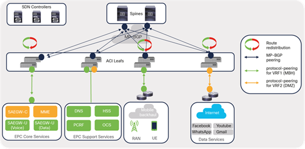
ACI fabric internal route distribution
MP-BGP is used within fabric leaf and spine switches in order to propagate external routes received by border leaf and EPC leaf switches. An ACI spine configured as route reflectors ensures that the redistributed routes are made available on other leaf switches (EPC Support Service leafs) in the fabric on which the VRFs exist. MP-BGP maintains a separate BGP routing table for each VRF instance.
3.6.1 BGP route reflectors
When configuring BGP route reflectors in an ACI fabric, an BGP ASN needs to be specified. The same BGP ASN can be used for both internal and external routing purposes. However, the ACI fabric provides an option to override the ASN used for the fabric’s internal routing and use of a different ASN when peering with external routers. The local ASN option is available under the BGP peer connectivity profile when configuring L3 external / L3Out for external peering.
3.7 Routing toward transport
Cisco ACI border leafs connect to the perimeter transport network toward the service provider core for routing to and from the edge and other locations in the telco landscape. For deployments involving multitenant networks, VRF-lite can be used to extend various VRF contexts between border leaf and the DC-PE core routers, as shown in Figure 49. Each VRF can use a dedicated physical or logical interface and routing protocol session to peer with the DC-PE routers. For deployment using segment routing in the core transport network, packets can be colored using DSCP on an ACI fabric that is mapped to the Segment Routing for Traffic Engineering (SR-TE) policy. The traffic can then be steered through the transport network.
ACI routing toward transport (IP handoff)
3.7.1 ACI SR-MPLS handoff
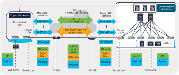
For large-scale deployments involving several VRFs extending to the core transport, configurations and operations become cumbersome, especially using VRF-lite with a large number of routing sessions. Cisco ACI Release 5.0 introduces SR-MPLS handoff, which, to a large extent, simplifies and unifies ACI-to-core transport connectivity design. Instead of having per-VRF session between ACI and the core network, a single control-plane session (MP-BGP EVPN) is used for all VRFs, as depicted in Figure 50.
The control plane session is built leveraging the following protocols:
● Underlay: BGP Labeled Unicast (BGP-LU) address-family is used for the underlay label exchange between ACI border leaf switches and connected data-center core routers (P/PE).
● Overlay: MP-BGP EVPN session for carrying fabric overlay prefixes and MPLS labels per VRF between border leaf switches and DC-PE routers
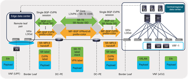
ACI routing toward transport (SR-MPLS handoff)
ACI to SR-MPLS handoff provides customers with the following key benefits:
● Unified SR/MPLS transport: SR/MPLS-based handoff from the data center allows the SP transport network to use single-data-plane encapsulation across the SP network and toward the data center.
● Automated and scalable handoff between the data center and transport: A single BGP session is used instead of per-VRF routing protocol and a sub-interface for connecting a VRF across the data center and SP transport.
● Consistent policy across the data center and transport: Using the BGP color community, customers are able to define policy for services in the data center and use the same BGP color community defined in the data center to define SR policies in transport. This provides a consistent policy definition across the data center and transport.
3.7.2 Cross-domain orchestration
Automation and orchestration forms the key block of the new 5G architecture that enables dynamic allocation of network resources for network slicing and other requirements. SR-MPLS handoff enables unified transport from ACI to the SR-MPLS core where prefix coloring and SLA requirements of a User- Plane-Function (UPF) is easily conveyed to the transport slice, thereby augmenting end-to-end cross-domain slice provisioning and segmentation automation. Cisco Network Services Orchestrator (NSO) can provision cross-domain orchestration across transport and the data center including handoff between ACI and SP transport.
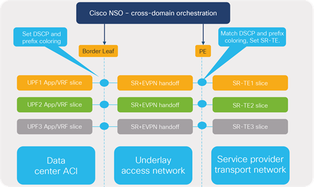
App/VRF slice mapping to SR-TE transport slice
ACI border leaf switches can advertise an EVPN type 5 prefix or a prefix with BGP color-extended community to the DC-PE routers. The routers can then create an SR-TE policy based on the community or destination prefix. In addition, traffic marked with DSCP values using EPG, contract, and L3Out Quality of Service (QoS) policies can be set with experimental bits (EXPs) or Class of Service (CoS) values for engineering the path using SR policy in the core transport network.
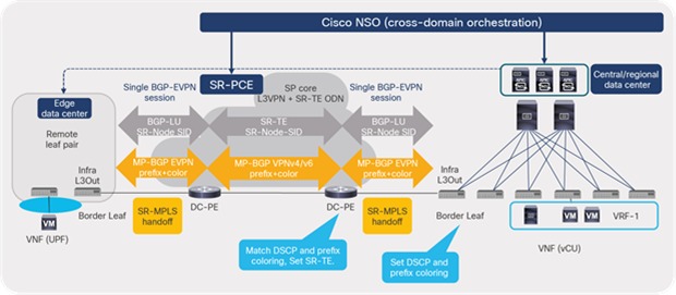
SR-MPLS: signaling of SR in transport
SR-MPLS: cross-domain orchestration through NSO
3.8 Routing toward VNFs
The focus of this section is on detailing the routing between the ACI fabric and the EPC core service interfaces facing the radio-access network; or, in other words, configured in the ACI core VRF. For easier explanation and illustration, EPC-S1-L3Out shall be used for this discussion; the same approach is applicable for the other two L3Outs (EPC Signal and EPC CP L3Out), as shown in Figure 54.
ACI routing toward EPC VNFs
As shown in Figure 54, EPC-S1-L3Out in this design connects to MME and SAEGW-U VNFs that include both VPC-DI and VPC-SI deployment options. The routings toward EPC VNFs deployed using VPC-DI or VPC-SI options are explained separately in later sections of this guide, for easier explaining and comprehension.
Table 9 lists the ACI L3Outs and the protocols used in this discussion for routing toward EPC VNFs.
Table 9. ACI L3 external: routing details
| ACI fabric (L3Out) |
EPC VNF |
EPC model |
L3 intf type |
Routing protocols |
BFD enabled |
| EPC S1-L3Out |
MME |
VPC-DI |
L3 SVI |
Multihop eBGP + static route |
Static routes |
| SAEGW-U |
VPC-SI |
L3 SVI |
Direct eBGP (SVI) |
eBGP |
|
| EPC Signal-L3Out |
MME |
VPC-DI |
L3 SVI |
Multihop eBGP + static route |
Static routes |
| SAEGW-C |
VPC-DI |
L3 SVI |
Multihop eBGP + static route |
Static routes |
|
| EPC CP-L3Out |
MME |
VPC-DI |
L3 SVI |
Multihop eBGP + static route |
Static routes |
| SAEGW-C |
VPC-DI |
L3 SVI |
Multihop eBGP + static route |
Static routes |
|
| SAEGW-U |
VPC-SI |
L3 SVI |
Direct eBGP (SVI) |
eBGP |
3.8.1 Routing toward VPC-DI
For EPC S1-L3Out, MME is part of the control-plane elements of the EPC Core deployed using a VPC-DI approach with CF (2), SF (10), and DI network (L2 VLAN), as depicted in Figure 55. Since the MME VNF compute nodes are grouped into host aggregates, the peering is minimized to only the ACI leaf switches that host the compute nodes that are part of host aggregate.
ACI routing toward MME (VPC-DI)
3.8.1.1 Physical design
From a physical connectivity perspective, a typical design involves dedicating two SRIOV interfaces on each compute node for carrying DI-network traffic and two SRIOV interfaces for carrying the provider or data traffic. The interfaces carrying DI traffic are dual-connected to the leaf switches in the rack in active/standby teaming. The interfaces carrying data or L3 VLANs (SVI A and B) are individual interfaces and are dual-connected to the leaf switches.
Figure 56 shows the SRIOV interface connectivity to ACI leaf switches from each compute node. The respective VLANs (L2/L3) are statically bound to the SRIOV interfaces of the leaf ports under the ACI core tenant.
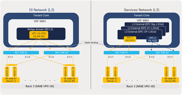
ACI to compute node physical connectivity (MME)
Each SF VM is configured with two VLAN interfaces (SVI A and B) that are used for data traffic and logically connected to leaf switches. The EPC elements that are part of the EPC-S1 L3Out (MME and SAEGW-U) use the same VLANs (SVI A and B) for logical connectivity. For simpler illustration, only the MME is shown in Figure 57.
L3 external SVI interfaces (MME only)
3.8.1.2 Routing protocol
The routing protocol, in the design, between ACI leaf switches and VPC-DI ensures the reachability of the EPC subnets (using service loopback addresses) from eNodeBs in the radio-access network. ACI L3Out advertises the routes received from VPC DI toward mobile backhaul. Similarly, the eNodeB address ranges received from the mobile backhaul routers are advertised toward MME instances
As shown in Figure 58, MME VNF peers with the four leaf switches using loopback interfaces. Since routing is a control plane function, the CF VM (such as a supervisor module) hosts the loopback interfaces used for eBGP peering. Odd-numbered leaf switches peer over BGP loopback interface L01, and even switches peer over BGP loopback interface L02. The service loopback addresses on MME VNF are advertised to eBGP toward the ACI fabric. Similarly, the ACI fabric advertises the eNodeB address range toward the VNFs.
ACI multihop eBGP peering with MME
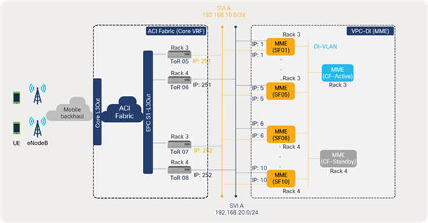
3.8.1.3 Static routing
Static routing in the design provides eBGP loopback address reachability as well as traffic distribution or Equal-Cost Multipathing (ECMP) across all SF VMs. On each leaf switch, a static route is configured destined toward the BGP loopback address of the MME, with the next hop being the SVI addresses of the SF VMs (10).This provides 10 paths for the leaf switches to reach the eBGP loopback addresses.
Similarly, MME VPC-DI has a static route configured toward the eBGP loopback addresses of each leaf switch, with the next hop being the leaf SVI address. In addition, each static route also includes all SF VM interface numbers. This provides 10 paths for the MME to reach the eBGP loopback address of a leaf switch. This enables traffic ECMP for the return traffic from MME toward the ACI fabric top-of-rack switches.
Enabling BFD on static routes avoids traffic blackholing in the deployment. When an SF VM or compute node fails due to an unplanned event, BFD can detect the failure and remove the failed path from its forwarding table. The traffic is distributed across the remaining paths toward the available SF VMs.
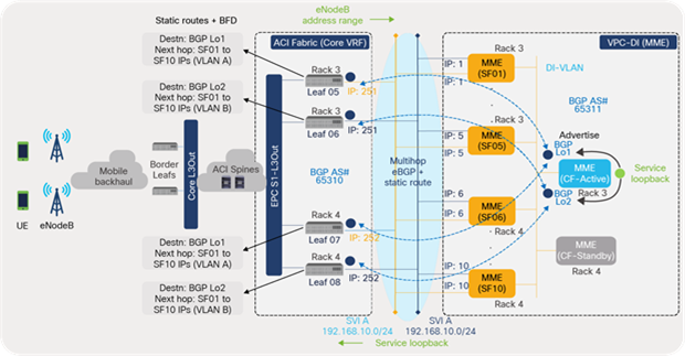
L3 external static routing
3.8.1.4 Traffic distribution
Traffic distribution to SF instances is achieved using the ECMP method provided by the ACI fabric as illustrated in the section “ECMP” of this guide.
3.8.2 Routing toward VPC-SI
The SAEGW-U elements are part of the user-plane or data-plane elements of the EPC Core solution. SAEGW-U instances handle the actual Internet data traffic from mobile subscribers. For this discussion, SAEGW-U elements are deployed using a VPC-SI approach with a total of 20 instances. Unlike VPC-DI, each instance in VPC-SI is treated as an independent device that is expected to peer with the ACI leaf switches that host the compute nodes part of the device’s host aggregate.
Since, for this discussion, the ICSR feature is leveraged along with the host aggregate, each SAEGW-U pair (active or standby) peers with the leaf switches in the racks, as shown in Figure 60. For instance, SAEGW-U active and standby instances that are part of Host-Aggregate 1 peer with the leaf switches in rack 1 and 2. If an active instance fails, the corresponding standby instance takes over the forwarding function.
ACI routing toward SAEGW-U (VPC-SI and ICSR)
3.8.2.1 Physical connectivity design
Since each instance is an independent device in the VPC-SI model, there is no requirement for a DI network as in VPC-DI. From a physical connectivity perspective, two SRIOV interfaces are dedicated on each compute node carrying the provider or L3 VLAN traffic and are dual-connected to the leaf switches.
Figure 61 depicts the SRIOV interface connectivity to ACI leaf switches from each compute node hosting VPC-SI VNFs. The respective VLANs (L3) are statically bound to the SRIOV interfaces of the leaf ports under the ACI core tenant.
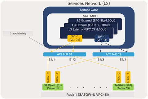
ACI to compute node physical connectivity (SAEGW-U)
3.8.2.2 Routing protocol (eBGP)
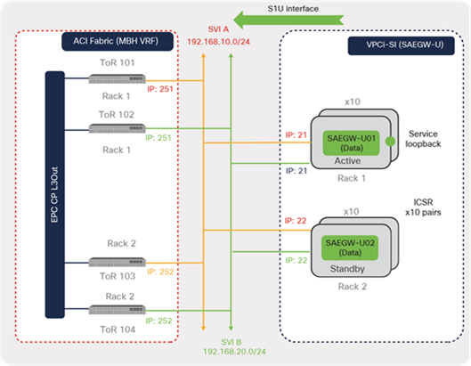
The L3 design between ACI and EPC SAEGW-U VNFs employs direct eBGP peering over SVI for route advertisement and reachability of the service loopback addresses from eNodeB. Each of the SAEGW-U instances using a VPC-SI deployment option is treated as a separate instance and peers with ACI leaf switches.
As shown in Figure 62, each instance in an ICSR pair (active and standby) peers with the local leaf switches in the rack that is using SVI interfaces. Odd-numbered leaf switches peer over the SVI A interface, and even switches peer over the SVI B interface. Service loopback addresses are advertised to eBGP from the active instance toward the ACI fabric. Therefore, traffic is always destined to the active instance in each ICSR pair.
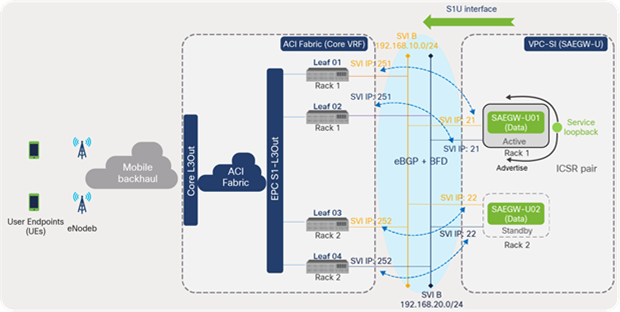
ACI direct eBGP peering with SAEGW-U
3.8.2.3 Traffic distribution
Traffic distribution in VPC-SI deployments (SAEGW-U) is handled differently from VPC-DI deployments. In the VPC-DI model, ACI fabric distributes traffic to SF VMs using ECMP forwarding that is achieved using static routing and multihop eBGP. However, for SAEGW-U leveraging the VPC-SI deployment model, the control-plane element (SAEGW-C) ensures subscriber distribution to multiple SAEGW-U instances.
As part of the user-endpoint attachment process, SAEGW-C is responsible for selecting a SAWGW-U instance that would be responsible for serving data traffic coming from the subscriber’s handset. This SAEGW-U selection process is configurable on SAEEGW-C; one of the options could be a round-robin method. Based on the selection process configured, SAEGW-C ensures that multiple subscribers are distributed to different User-Plane (UP) instances for serving data traffic.
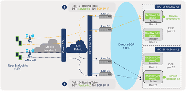
As illustrated in Figure 63, the Internet data traffic from the user endpoint is encapsulated by eNodeB with a GTP-U tunnel header and sent to the S1U interface (service loopback address). The ACI leaf switch does a lookup of the destination service loopback address and forwards the traffic to the SAEGW-U active instance SVI address. Traffic from multiple user endpoints is distributed across multiple SAEGW-U instances depending on the subscriber pool assigned to the instances.
Traffic distribution to SAEGW-U (VPC-SI)
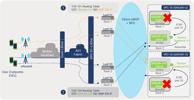
As depicted in Figure 64, failure of an active instance in rack 1 triggers an ICSR switchover to standby instance in rack 2. The standby instance assumes the active role and starts advertising the service loopback addresses. Traffic received by the ACI leaf switches is forwarded to the new active SAEGW instance.
Traffic distribution to SAEGW-U (ICSR failure case)
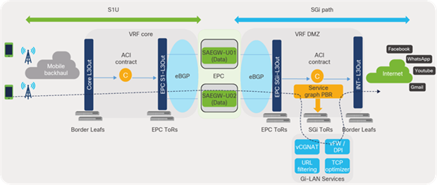
3.8.3 End-to-end flow
SAEGW-U instances process the traffic received over the S1U interface in the core VRF and forward the traffic from SGi interfaces in the DMZ VRF toward the Internet. The traffic (SGi), prior to reaching the Internet, can be intelligently steered toward Gi-LAN Services for value-added services using ACI service graphs and policy-based redirect features. Gi-LAN Services design is covered in detail under the section “Gi-LAN Services design” in this guide.
EPC end-to-end flow (high-level)
3.8.4 ACI contracts
ACI contracts and filters are required for allowing communication between external EPGs; by default, no communication is allowed in Cisco ACI. Filters allow or deny traffic selectively based on protocol type and L4 ports. Figure 66 depicts contract requirements between external EPGs to allow traffic from mobile backhaul toward EPC Core Service interfaces that are part of EPC S1-L3Out.
Allowing traffic toward VNFs (EPC S1-L3Out)
3.8.5 Route control
For route control, specific prefixes can be configured using the Export Route Control Subnet option under external EPG of EPC S1-L3Out to be advertised toward EPC elements. Similarly, the service loopback prefixes received from EPC Core Services are advertised specifically on core L3Out toward mobile haul. It is to be noted that the ACI fabric automatically redistributes external prefixes learned by an L3Out into MP-BGP without any user configuration.
Figure 67 illustrates the route advertisement along the path between EPC elements in a telco data center and eNodeB in mobile backhaul.
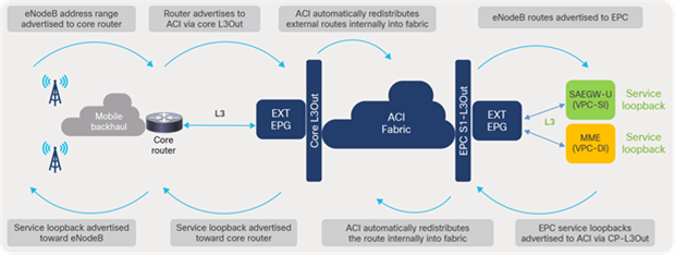
ACI fabric route control
3.9 Remote leaf for distributed telco data centers
With the emergence of 5G architecture, which is focused on providing better experiences to subscribers, services are virtualized, decoupled (CUPS), disaggregated, and placed closer to the user at the edge or aggregation locations in the telco landscape. With this distributed architecture the data-center footprint increases, thereby increasing also the number of management touchpoints.
Figure 68 depicts the distributed telco data center locations where packet-core services are distributed across central and edge locations of telco data centers.
EPC distributed architecture
Centralized management and consistent policy across these distributed architectures are essential for simplified management and operations. With this approach, automation and orchestration are simplified to a large extent since a central orchestrator such as Cisco NSO needs to integrate with only one element – in this case, an SDN controller – instead of integrating with individual components spread across locations.
Cisco remote leaf solutions provide centralized management of these data centers by providing full day-0 and day-1 automation, consistent day-1 policy, and end-to-end troubleshooting across any location. As depicted in Figure 69, remote leaf architecture involves a pair of leaf switches deployed in edge locations that are managed and operated by APICs in a central or regional location. This solution requires logical connections between the remote leaf switches in the edge to the spines in the main data center over an IP network.
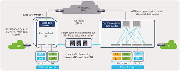
Remote leaf for an edge telco data center
Remote leaf architecture provides the following business and operational benefits for a distributed telco data center architecture:
● Extension of the ACI policy model outside the main data center to remote sites distributed over an IP backbone
● Extension of the ACI fabric to small data-center locations without investing in a full-blown ACI fabric
● Single pane of management for the fabric distributed across central, regional, and edge locations
● Full day-0 and day-1 deployment automation and consistent policy and monitoring for day-2 operations
● Local traffic forwarding between the endpoints or services connected to the remote leaf switches
● SGi service chaining along with Policy-Based Redirect (PBR) at edge locations and local traffic forwarding independent of central or regional locations
● ERSPAN monitoring and troubleshooting for endpoints connected to edge locations
Note: For more information on the remote leaf solution, see the Cisco ACI white paper available at the following link: https://www.cisco.com/c/en/us/solutions/collateral/data-center-virtualization/application-centric-infrastructure/white-paper-c11-740861.html
3.9.1 Traffic flow requirements
Edge locations in a distributed architecture can involve EPC micropod CVIM deployment with fewer compute nodes dedicated to or cohosting key EPC elements such as UPF and Gi-LAN Services. Figure 70 depicts high-level logical connectivity requirements for a distributed packet-core leveraging a remote CUPS architecture. The inter-data-center communication between the edge and the central data center is used mainly for signaling and other control-plane purposes using Sx and S1-MME interfaces. The data-plane or user-plane traffic is serviced locally using S1U and SGi interfaces from the edge locations closer to the user endpoints.
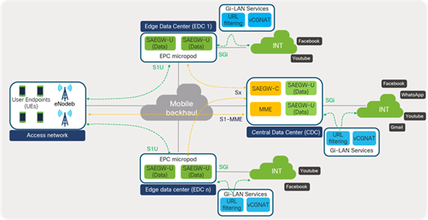
EPC interfaces in a distributed architecture (high-level)
3.9.2 Design considerations
A generic design might involve communication utilizing the IP Network (IPN) between the fabric in the data center and remote leaf switches. Depending on L2/L3 extension requirements, this is achieved by extending the VRF, BD, and EPG across the locations and enabling communications over the iVXLAN overlay. However (specifically for a telco distributed data centers environment), network operators might, for various reasons, prefer using the communication over the WAN or a core transport network; for example, for enabling data center to data center traffic flows over MPLS using the existing monitoring tools or transport network slicing requirements. In such cases, a separate VRF or tenant could be dedicated to each DC (ACI Pod, ACI site, or ACI remote leaf) to ensure that the traffic flows over a WAN or core transport network instead of over IPN.
Figure 71 depicts control-plane traffic flow between the user plane at the edge location and the control plane at the central location over a core transport network.
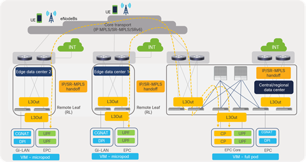
Remote leaf core transport connectivity
The user plane in edge locations can locally forward traffic to the Internet and can leverage the service chaining function using service graph and PBR for SGi traffic, as depicted in Figure 72.
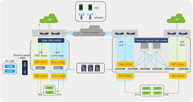
Remote leaf logical design
The Gi-LAN Services block in the telco data center architecture offers enhanced security and value- added services for Internet data traffic from mobile subscribers. Service functions such as Carrier-Grade Network Address Translation (CGNAT), firewall, parental control, URL filtering, Deep Packet Inspection (DPI), content optimization, etc., are leveraged to deliver a high-quality and secure data-service experience for subscribers.
This section focuses and expands on some of the key requirements that are part of the Gi-LAN Services block and how these requirements can be achieved using intelligent traffic-steering features. Figure 73 shows how SGi traffic handled by SAEGW-U is steered toward an EPC DATA Services (SGi) block before reaching the Internet.
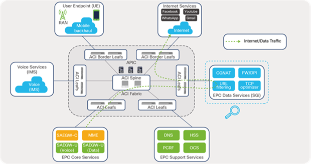
ACI traffic steering to Gi-LAN Services
The example used in this design considers a multinode services use-case deployed using an L4-L7 service graph in unmanaged mode. The service nodes are hosted on Cisco NFVI as VNFs and are deployed in routed mode (L3). Because several variations in the design and traffic flows are possible, the design used as an example in this section of the guide may not exactly reflect your environment.
Service chaining is a very common use case in telco data centers or telco cloud. Services, such as OTT caching and Gi-LAN Services, that leverage a remote CUPS model, which is essential to moving toward 5G networks, are also moving to edge data centers or to the cloud. This trend brings additional complexity as multiple data centers and clouds are managed and operated as distinct entities using separate management and policy controls.
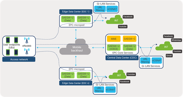
Gi-LAN requirements for distributed telco data centers
The Cisco ACI intelligent service chaining function allows operators to utilize the RESTful API or GUI interface of APICs to define service chaining using simplified policies. The APIC then translates the logical service graph to a concrete switch configuration and deploys to the required ACI leaf switches that participate in the service chaining function. This innovative approach brings multiple benefits:
● Ease of configuration because service nodes are handled in a group rather than as individual nodes
● Easy expansion by simply adding additional devices in a group without changing the overall service policy configuration
● Automatic load balancing of traffic across service nodes
● Automatic symmetricity of traffic
● Automatic health check of service nodes and rebalancing of traffic
● Bypassing and reinsertion of the service group in a chain, based on threshold
When using the remote leaf feature in remote or edge data centers or the cloud, the service chaining policies can be centrally deployed and managed for Gi-LAN Services deployed in these locations.
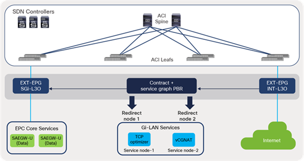
ACI fabric intelligent service chaining
4.1.1 Traffic flow requirements
In telco or edge data centers, the user-plane function (SAEGW-U) is responsible for handling Internet data traffic from the user endpoint. The data traffic is received from the user endpoint over an S1U interface and is sent over an SGi interface to the Internet. The data traffic prior to reaching the Internet needs to be steered through one or more service function nodes that provide security, optimization, and other value-added services to the data traffic.
The following are some key flow-requirements for this Gi-LAN Services block:
● Service-chaining support where traffic (IPv4/IPv6) can be steered to flow in a specific sequence through multiple service nodes before reaching the Internet
● Traffic symmetry must be maintained for ongoing and return traffic: that is, the same service node(s) must also serve the return traffic for a given flow.
● Design flexibility in terms of steering traffic through specific service node(s) and bypassing some service node(s) based on traffic type. For instance, all traffic (IPv4/IPv6) must flow through service node 1, whereas some IPv6 traffic must bypass service node 2.
● Resiliency. The design must be resilient in handling components and link failures along the path.
● Seamless scale-out. The design must allow seamless scale-out of services in future to cover increases in traffic volume.
Figure 76 shows a sample SGi flows illustrating traffic steering through different service node types based on traffic type.
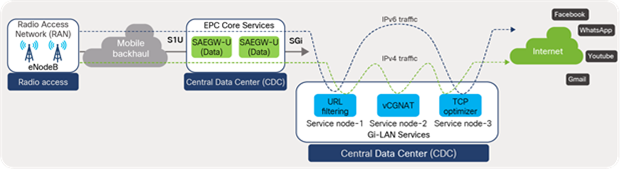
Gi-LAN Services traffic flow
Note that, because various permutations and combinations of flows and service function types are possible, the example used in this discussion may not exactly reflect your environment. This section aims to provide the reader with the right focus areas and design considerations when designing service chaining for telco or edge data-center environments.
4.1.2 EPC subscriber/user-endpoint pools
A mobile network can be designed and deployed to support native IPv6, IPv4, or dual-stack deployments. Based on the design, a mobile handset or user endpoint is assigned an address (IPv4, IPv6, or dual-stack) from the subscriber pool range, for accessing internet data. SAEGW-C ensures subscriber distribution to multiple SAEGW-U instances, enabling traffic to be distributed across the SAEGW-U instances.
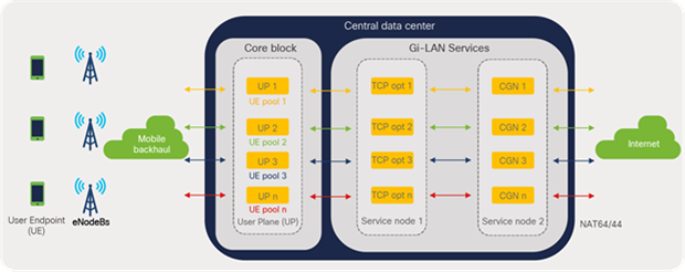
Subscriber / user-endpoint traffic distribution
As shown in Figure 77, all user-plane instances (SAEGW-U) actively participate in traffic forwarding coming from multiple mobile subscribers.
In the example used in this discussion, all traffic is steered through service node 1 for TCP optimization services; in addition, traffic destined for IPv4 destinations on the Internet flows through CGNAT instances that perform NAT64 and NAT44 functions.
4.1.3 ACI PBR service graph design
Service insertion in the Gi-LAN block is achievable using a traditional approach. However, such an approach involves complex configurations on both the network and service nodes involved in the design. To achieve symmetric traffic patterns, complex routing, and Policy-Based Redirect (PBR) rules need to be configured separately using a node-by-node approach for onward and return traffic.
Cisco ACI simplifies service-function insertion or removal for traffic selectively through service graph and symmetric PBR. Through simple policy configurations, SGi traffic can be selectively steered to certain service function node(s), based (for example) on protocol and L4-L7 port.
Cisco ACI takes a device-group approach for service chaining rather than node by node. The subscriber pool traffic can be redirected as a whole to a device group containing all service nodes, as depicted in Figure 78. The Cisco ACI symmetric PBR feature ensures that the same device is picked in SAEGW to the Internet, and the Internet to SAEGW in a group, based on hash value. The hash tuple is, by default, the source-IP address, destination-IP address, and protocol type. Traffic symmetry is maintained for a flow without any extra configuration.
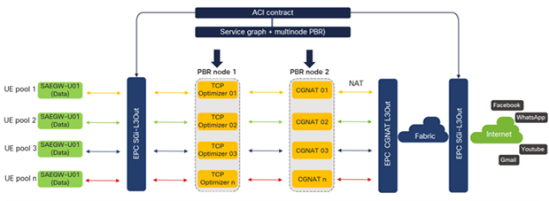
ACI PBR service graph design
4.1.4 Service graph template
Using a service graph template, Cisco ACI allows a user to define the required service functions to be inserted between two endpoint groups within the fabric. Service nodes that have been defined under ACI tenant L4-L7 devices policy can be inserted with the intended sequence under this template. For flows requiring traffic steering, the Route Redirect option is checked under the respective service node when defining the service graph template.
The following figure depicts a service graph template with multiple services (TCP optimizers and CGNAT) along with the Route Redirect option checked.
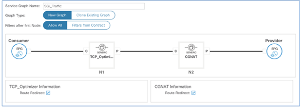
Screenshot of ACI PBR service graph template from APIC controller
Once the template is defined, it can be applied to various traffic flows by selecting the consumer and provider EPGs and associating them with a contract. Customers can define EPGs based on prefixes or VLANs. For example, the subscriber pool prefix range can be a consumer EPG, and the Internet prefixes can be the provider EPG. Traffic can be selectively steered through the service nodes based on filters.To save a configuration effort, this template can be reused multiple times for different traffic flows.
The screenshot below in figure 80 shows a service graph template being applied between SGi and INT L3Out, allowing SGi traffic to be redirected to the two service nodes before reaching the Internet.
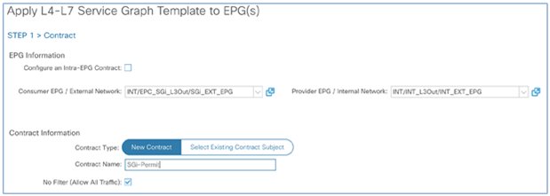
Screenshot from APIC to apply contract between EPGs to perform service chaining
Once the service graph template is applied, the APIC automatically pushes the policy-based redirection rules to the respective consumer (SGi-L3Out) and provider (INT-L3Out) leaf switches involved in service chaining. In addition, the APIC automatically creates the required internal EPGs for the service-node connectors. For example, N1-Consumer/Provider and N2-Consumer in Figure 81 are created by the APIC internally as part of the service graph deployment.
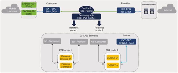
Service graph policy programming
4.1.5 NAT considerations
For an ACI service-graph PBR design involving service nodes such as CGNAT, one of the key considerations is to configure L3Out between the ACI fabric and the CGNAT external leg, as shown in Figure 80 (CGNAT L3Out). This is because CGNAT performs source Network Address Translation (NAT), and the NAT pool ranges are outside of the local segment. Therefore, a L3Out is required for the ACI fabric to route the return traffic from the Internet destined to the NAT IP addresses. This use case is called unidirectional PBR with the other connector in L3Out and is supported from Cisco ACI Release 4.1.2 onwards, as depicted in Figure 82.
In this design, NAT device should be the last node in the group. Since NAT service is the last node, the source IP and destination IP reverses in forward and reverse direction before the NAT device. This ensures that symmetric PBR behavior works fine for TCP optimizers. Source IP address translation performed by CG-NAT doesn’t impact the symmetic PBR functionality.
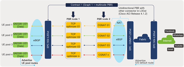
Service-graph NAT considerations
4.1.6 Service BD considerations
For ACI service-graph PBR design, the service function nodes in the Gi-LAN Services block must be connected to Bridge Domains (BDs). Each leg or connector on each service node (consumer or provider) must be connected to dedicated bridge domains and must not be shared with other endpoints. The service bridge domains must be configured with endpoint dataplane learning disabled. Since this reference design involves CGNAT, a service BD is dedicated only for the consumer connector of the CGNAT node while the provider connector is connected to L3Out, as depicted in Figure 83.
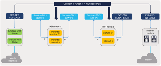
Gi-LAN Services BD considerations
Table 10 lists the bridge-domain allocations and key options to be selected for deployment in an ACI fabric.
Table 10. Cisco EPC: deployment models
| Service node |
Bridge Domain |
IP |
Unicast Routing |
Data Plane Learning |
L2 Unknown Unicast |
| Node 1 |
Service-BD1 |
10.10.10.1/28 |
Enabled |
Disabled |
Flood |
| Node 1 |
Service-BD2 |
10.10.20.1/28 |
Enabled |
Disabled |
Flood |
| Node 2 |
Service-BD3 |
10.10.30.1/28 |
Enabled |
Disabled |
Flood |
4.1.7 L4-L7 devices
As a predeployment procedure, prior to applying service graph, the service-node pools (such as TCP optimizers and CGNAT device instances) must be defined under the L4-L7 devices of a tenant. Through this configuration, the paths to the service nodes are specified (leaf and interface). The following snapshot in figure 84 shows an example of defining service device instances under L4-L7 devices under the ACI tenant.
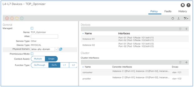
Screenshot from APIC to define a service device cluster
4.1.8 PBR policy
The Policy-Based Redirect (PBR) policy allows a user to define the IP and MAC addresses of a service node to which the traffic needs to be redirected. In addition, the monitoring policies and the hashing algorithm are chosen to monitor and distribute the traffic to the service nodes in a group.
The following screenshot in figure 85 displays Cisco ACI’s PBR policy from the APIC.
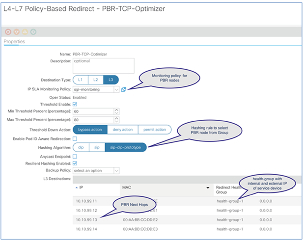
Screenshot from APIC to define PBR policies
4.1.9 Routing considerations
From a routing point of view, it is important to ensure reachability of routes for both forward and return traffic. For forward traffic from SAEGW-U destined to the Internet, a typical design would involve advertising default routes from the perimeter Internet routers to the ACI fabric. The fabric can then advertise this default route toward SAEGW-U and CGNAT instances over the eBGP routing protocol used in this case.
For the return traffic from the Internet sources destined toward the user-endpoint address, the design must consider the reachability of user-endpoint NAT pool routes from the Internet routers. The ACI fabric in this case advertises the user-endpoint NAT pool routes received from CGNAT instances toward the Internet routers for the return traffic. Since CGNAT does source NAT, the return traffic from the Internet is destined toward the NAT address, and the ACI fabric is able to route the traffic toward CGNAT.
Figure 86 illustrates the routing considerations for a Gi-LAN Services design leveraging the ACI service graph and PBR features.
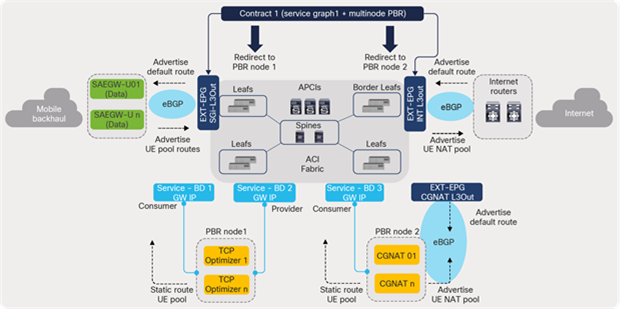
Gi-LAN routing considerations
The ACI fabric ensures that the user-endpoint pool routes received from SAEGW-U instances are made available on the services leaf switches through internal route redistribution using MP-BGP. When CGNAT receives the return traffic, it can perform a destination NAT of the original user-endpoint address and route it to the ACI fabric, to be forwarded to SAEGW-U instances. Service function nodes in the service graph design employ static routing when deployed in routed mode.
4.1.10 End-to-end packet flow
This section explains end-to-end packet flow for both forward and return traffic. Figure 87 shows an example of how subscribers and SGi traffic from SAEGW-U instances (02 and 04) are steered and distributed across service nodes before reaching the Internet. Following is the packet flow sequence from ACI fabric to internet:
1. ACI fabric does a route and security policy lookup on the SGi traffic received from SAEGW-U and destined toward the Internet IPv4 destination address.
2. Policy lookup on ACI matches the contract policy with the source as the SGi external EPG and the destination as the INT external EPG
3. Since a service graph is attached to the contract, a match triggers a redirect action toward PBR node 1 consumer interface (N1-Consumer). Traffic is redirected to the service nodes in the node-1 group based on hashing. The hash tuple, by default. is the source IP address, the destination IP address, and the protocol type.
4. PBR node 1 instances forward the traffic to ACI on the provider side after servicing the traffic. Policy lookup on the ACI fabric matches the contract policy with the source as the N1-Provider EPG and the destination as the INT external EPG. A match triggers a redirect action again to the PBR node 2 group consumer interface (N2-Consumer). Traffic is redirected to the service nodes in the node-2 group based on hashing.
5. CGNAT instances do a source-NAT and forward the traffic to the ACI fabric over the provider connector, which is an L3Out interface.
6. Policy lookup on ACI matches the contract policy with the source as the CGNAT external EPG and the destination as the INT external EPG. As a result, traffic is permitted and forwarded toward the Internet.
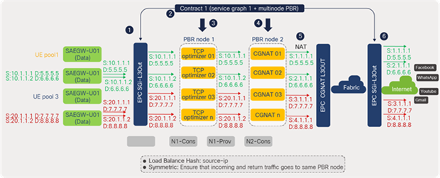
Gi-LAN packet flow: forward traffic
Figure 88 shows an example of how the return traffic from the Internet is steered and distributed across the multiple service nodes before reaching its destination user-endpoints via an SGi interface. Following is the packet flow sequence from Internet to ACI fabric:
1. Traffic from the Internet sources destined for the user-endpoint address is routed to CGNAT instances by the ACI fabric, because the traffic is destined to the user-endpoint NAT addresses. CGNAT does destination NAT and forwards the traffic destined to the original user-endpoint address to the ACI fabric.
2. Policy lookup on ACI matches the contract policy with the source as the N2-Consumer EPG and the destination as the SGi external EPG. A match triggers a redirect action toward the PBR node 1 provider interface (N1-Provider), and the traffic is redirected to the service nodes in the node-1 group based on hashing. Note that the traffic is served by the same PBR node that serviced the forward packet for the flow, thereby maintaining traffic symmetry.
3. PBR node 1 instances forward the traffic to ACI on the consumer side after servicing the traffic. The traffic is permitted on ACI because the policy lookup matches the contract policy with the source as the N1-Consumer EPG and the destination as the SGi external EPG.
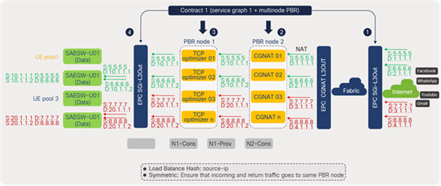
Gi-LAN packet flow: return traffic
4.1.11 Gi-LAN Services resiliency
This section discusses some of the key Cisco ACI PBR features, such as service-node tracking, resilient rehashing, and backup policy that enhances resiliency to Gi-LAN design. Handling requirements, such as tracking, traffic re-distrubution on failures, and maintaining traffic symmetry, from a single point simplifies the design and operations. A service-functions node can be tasked to provide its intended functions rather that spending cycles in meeting these requirements.
4.1.11.1 Service-node tracking
Service-node tracking (available in Cisco ACI Release 3.1 and after) helps prevent traffic black-holing during individual node failure events. Cisco ACI can be configured to track the service-node interfaces in the group through ICMP (IPv4 or IPv6) or TCP probes, as depicted in Figure 89. On node or interface failure, ACI removes the failed node from the PBR group and ensures traffic distribution to the remaining available nodes in the group.
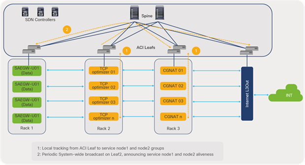
Service-node tracking
During multinode failures of a specific function, should the remaining available nodes fail to meet throughput or capacity requirements, the ACI fabric can be configured to completely bypass the service function in the path. This can be achieved by configuring minimum and maximum threshold values based on the percentage of available nodes in a group-and-bypass action. For instance, in Figure 89, if the threshold value falls below the minimum percentage due to a multiple TCP optimizer instances failure, and a bypass action is configured, the traffic bypasses the node 1 group and is redirected to the CGNAT instances in the path.
4.1.11.2 Resilient rehashing
During a service node failure, traffic is, by default, rehashed to the available nodes in the group. During this process, even though some traffic that was not going through the failed node group due to rehashing of all flows after failure. to a new node. Using the resilient rehashing feature (available from Cisco ACI Release 3.2 onward), only the traffic that went through the failed node is redirected to one of the available PBR nodes. Other traffic continues flowing to the same nodes or path unaffected, as illustrated in Figure 90.
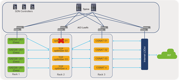
Resilient hashing
The above case might lead to a situation where one of the available nodes is left to carry double the traffic. If capacity and throughput are a concern, the Gi-LAN Services can leverage ACI Backup PBR policy (available from Cisco ACI Release 4.2 onward). This allows the service-node deployment to include a backup service node, only to be used at the time of a node failure. This prevents an available node to be overloaded and instead allows a dedicated backup node to accommodate the traffic, minimizing capacity concerns.
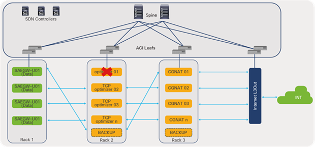
ACI backup PBR policy
The following white paper provides in-depth information about implementation of policy-based redirect and service chaining in Cisco ACI.
EPC Support Services elements, such as Home Subscriber Server (HSS), Policy and Charging Rules Function (PCRF), etc., are key functional elements of the Evolved Packet Core (EPC) network. Though these elements are part of the EPC Core Services, they are categorized as Support Services, based on how they connect to the Cisco ACI fabric. Unlike the EPC Core Services block, which connects to the ACI fabric over a Layer 3 routed interface, the support services elements such as HSS, PCRF and others, connect to the ACI fabric as server VMs or endpoints to which ACI provides a pervasive gateway function.
This section focuses on the requirements and design considerations for connecting EPC Support Services to a Cisco ACI fabric in telco data centers.
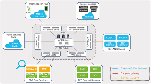
ACI fabric connectivity to EPC Support Services
5.1.1 Network requirements
Each of the services under the EPC Support Services can span several VLANs or segments, depending on the scale of the deployment. Typically, for services provided by third-party vendors, the VLAN and IP address requirements (VLANs and segments) are provided by the service vendors.
Cisco ACI offers the capability to build network constructs based on the application or service requirements rather than a traditional VLAN or network approach. Depending on requirements and scale, each service can be assigned an endpoint group (EPG) defined under the application profile and can control communication through contracts and filters. A telco data center or a cloud administrator gets a holistic view of the network as application services hosted on it rather than VLANs and network subnets, as shown in the screenshot below in figure 93.
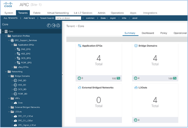
Screenshot from APIC to show application view in SDN controller
5.1.2 Pod placement and VM mobility
Compute nodes dedicated to hosting support-service elements can span multiple racks and can be configured in host aggregates. VM mobility, in which a VM can move to any compute node across a rack within a host aggregate, is one of the key requirements of the design.
Cisco ACI, built on a VXLAN overlay fabric, enables Layer 2 forwarding over a Layer 3 network. This solution offers a full-mesh, loop-free topology without the need for a spanning-tree protocol to prevent loops. VMs can move between compute nodes across any racks, and the ACI fabric ensures seamless connectivity. For deployments involving an ACI OpenStack plug-in, the APIC automatically configures the appropriate policies on each leaf switch and, optionally, on the virtual switch as well. As virtual machines migrate, policies are automatically updated as well. For static deployments, it must be ensured that the EPGs are statically bound to all of the required leaf switches and ports connecting to the compute nodes in the host aggregate.
5.1.3 Tenant/VRF considerations
One of the key considerations when planning for EPC Support Services connectivity to a Cisco ACI fabric is deciding on tenant and VRF placement. The support services form the control plane in the EPC architecture and require communication with EPC Core Services such as MME and SAEGW-C in the solution. Therefore, placement of the VRF typically aligns with that of the EPC Core Services in the design.
Multitenancy is built into Cisco ACI from the beginning. ACI requires a user to configure a tenant and VRF first before starting to build network constructs. Telco data center environments benefit from the Cisco ACI multitenancy model by segregating traffic based on the environment, such as core radio, management, and Internet and securing the environment operationally and within administrative boundaries.
Typically, each of the VMs hosted in an NFVI environment include, at a minimum, management and data interfaces. The management interface is used for VNF management and monitoring purposes and typically is configured to carry over the mLOM or OVS interfaces. The data or provider traffic is used for carrying data or application traffic. For EPC Support Services, the provider traffic can be configured to carry over the SRIOV or mLOM interfaces, depending on third-party vendor requirements.
Figure 94 shows the VRF configurations for the various parts of the EPC solution referenced in this discussion.
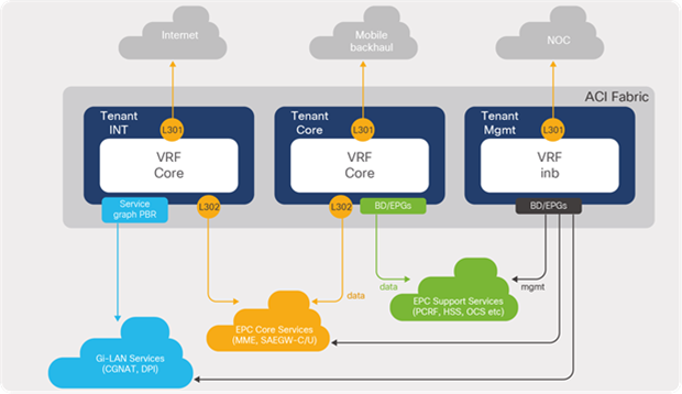
ACI tenant and VRF considerations
5.1.4 ACI logical constructs
For support service segments, Cisco ACI constructs such as bridge domains, application profiles, endpoint groups (EPGs), and contracts, can be configured under their respective tenants based on the connectivity requirements received from the service vendor. A typical telco data-center deployment includes one VLAN or a segment equivalent to one bridge domain and one EPG. Constructs such as application profiles and endpoint groups (EPGs) provide a way to structure and organize the different service segments under a folder and control communication through the contracts and filters. For this discussion, each of the services is assigned an EPG and bridge domain and is statically bound to the leaf ports connecting to the compute nodes where the VNFs reside.
Figure 95 depicts ACI constructs defined for the EPC Support Services under an ACI core tenant.
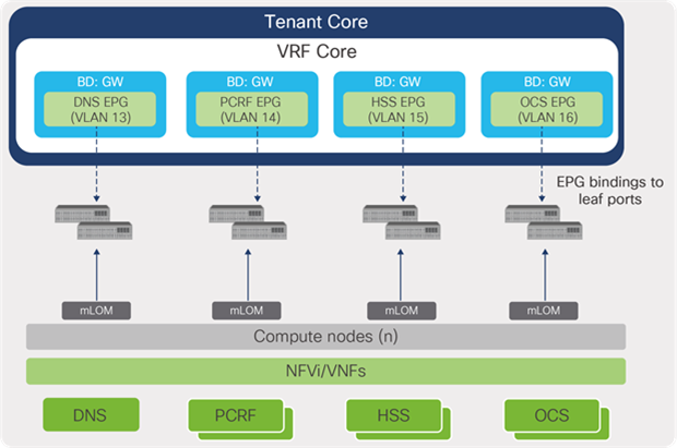
ACI logical constructs for EPC Support Services
For deployments integrating Cisco ACI with OpenStack, it is important to note that provisioning ACI constructs, including EPGs, bridge domains, and contracts, can be automated through the Cisco ACI OpenStack Unified Plug-in in response to actions taken through OpenStack Neutron APIs. The plug-in automatically maps Neutron networks and routers to EPGs, bridge domains, and contracts in ACI. VM instance creations and deletions across compute nodes are detected by the APIC, and appropriate EPG bindings and policies are created automatically on the respective leaf switches. As virtual machines migrate, policies are automatically updated as well.
With Cisco ACI, the ACI OpenStack plug-in is extended to include an automated L3Out (external connectivity) configuration. Cisco ACI locates VM or Virtual Network Function (VNF) locations through Link Layer Discover Protocol (LLDP), and uses this information to configure dynamically L3Outs (static routes or BGPs) on the APIC.
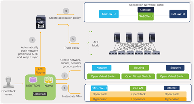
Cisco ACI OpenStack Unified Plug-in
5.1.5 Routing considerations
In order to access the support services from other blocks of the telco data center, it is important to ensure reachability of the service segments through the proper route advertisements. The communication requirements can be broadly categorized as follows:
● Inter-segment east-west: Communication between segments hosted within the support services block and VRF. This typically involves communication between VMs in two different endpoint groups and bridge domains.
● Inter-block east-west: Communication between EPC Support Services segments and the EPC Core Services block.
● Inter-block north-south: Communication between EPC Support Services segments and the radio-access network in mobile backhaul.
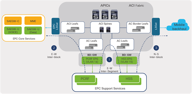
Cisco ACI fabric routing considerations
Inter-segment east-west communication is achieved through the ACI fabric VXLAN forwarding, with no extra configurations needed from a forwarding perspective. For inter-block east-west and north-south that involves L3 external interfaces, the Support Services segments need to be advertised by associating the corresponding bridge domains to the required L3 external or L3Out. In addition, it is mandatory for the “Advertised Externally” option to be checked under the bridge domains of the service segments.
5.1.6 Contract considerations
The Cisco ACI tenant VRF has the policy control enforcement preference set, by default, as enforced. This means that traffic between any two endpoint groups is not permitted until a contract is applied. For EPC Support Services EPGs to communicate with EPC Core Services elements or outside the telco data center, a contract needs to be applied, as shown in Figure 98.
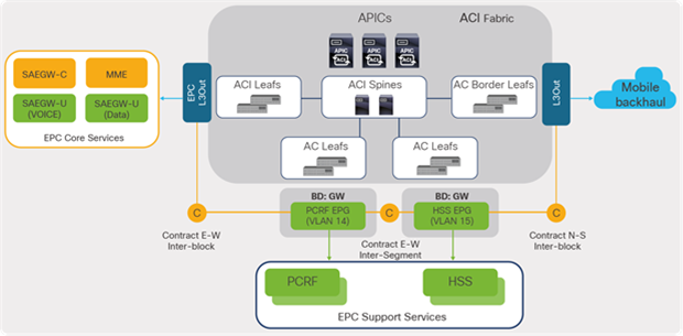
Cisco ACI fabric contract considerations
A contract can be defined per communication type (east-west or north-south), or it can defined per application or service, depending on the application policy requirements. Since contracts are basically policies that are programmed into the TCAM table in the ACI leaf hardware, it is important, in large-scale deployments, to take policy TCAM usage into consideration and ensure that the limits are not exceeded. An approximate calculation for the number of TCAM entries is as follows:
Number of entries in a contract * Number of consumer EPGs * Number of provider EPGs * 2
The ACI Forwarding Scale Profile Policy option provides flexibility to choose between different scalability options, such as endpoint scale, Longest Prefix Match (LPM) scale, IPv4 prefix scale, IPv6 prefix scale, dual stack scale, contract/policy scale etc. Depending on a scale requirement, customers can use right scale profile for a leaf. Applying a scale profile to a node requires a manual reload of that node; therefore, depending on the leaf function (border Leaf or compute leaf), the policy should be set during the initial deployment.
In summary, Cisco ACI provides a great solution for building a distributed telecom data center that provides consistent policy, automation, and operations for all data centers including edge, regional, and central data centers. There are some specific capabilities such as connectivity to Evolved Packet Core (EPC), service chaining, and SR/MPLS handoff, which make Cisco ACI a perfect choice to build a 5G-ready telco data center. This has been proven with multiple successful deployment and case studies.
References: -
ACI in Telco DC whitepaper
Design 5G Ready Distributed Telco DC with Cisco ACI
https://www.ciscolive.com/c/dam/r/ciscolive/us/docs/2020/pdf/DGTL-BRKSPM-2009.pdf
Case study of SP customers running ACI based SDN for telecom datacenter
https://www.ciscolive.com/c/dam/r/ciscolive/emea/docs/2020/pdf/BRKACI-3620.pdf