ACI Fabric L3Out White Paper
Available Languages
Bias-Free Language
The documentation set for this product strives to use bias-free language. For the purposes of this documentation set, bias-free is defined as language that does not imply discrimination based on age, disability, gender, racial identity, ethnic identity, sexual orientation, socioeconomic status, and intersectionality. Exceptions may be present in the documentation due to language that is hardcoded in the user interfaces of the product software, language used based on RFP documentation, or language that is used by a referenced third-party product. Learn more about how Cisco is using Inclusive Language.
The Layer 3 Out (L3Out) in Cisco Application Centric Infrastructure (Cisco ACI) is the set of configurations that define connectivity to outside of ACI via routing. The goal of this document is to explain thoroughly Cisco ACI design concepts and options related to the ACI L3Out. This document does not provide step-by-step configuration examples for all scenarios. Instead, its focus is on understanding the key concepts. Hence, the recommendation is to read this document with some basic understanding of ACI along with decent knowledge of standard routing protocols such as OSPF, EIGRP, BGP and MP-BGP.
Cisco ACI Layer 3 Out overview
The ACI fabric is formed from multiple components. Some of these components include bridge domains (BDs) and endpoint groups (EPGs) to provide Layer (L2) connectivity or default gateway functions for a group of endpoints. Another one is the Layer 3 Out (L3Out, or external routed network in Cisco APIC GUI prior to the APIC Release 4.2), which is to provide Layer 3 (L3) connectivity between servers connected to ACI and other network domains outside of the ACI fabric through routing protocol or static route.
Cisco ACI was originally built to be a stub network in a data center to manage endpoints. The ACI Layer 3 Out (L3Out) was initially designed only as a border between the stub network formed by ACI and the rest of the network, such as intranet, Internet, WAN, etc., not as a transit network.
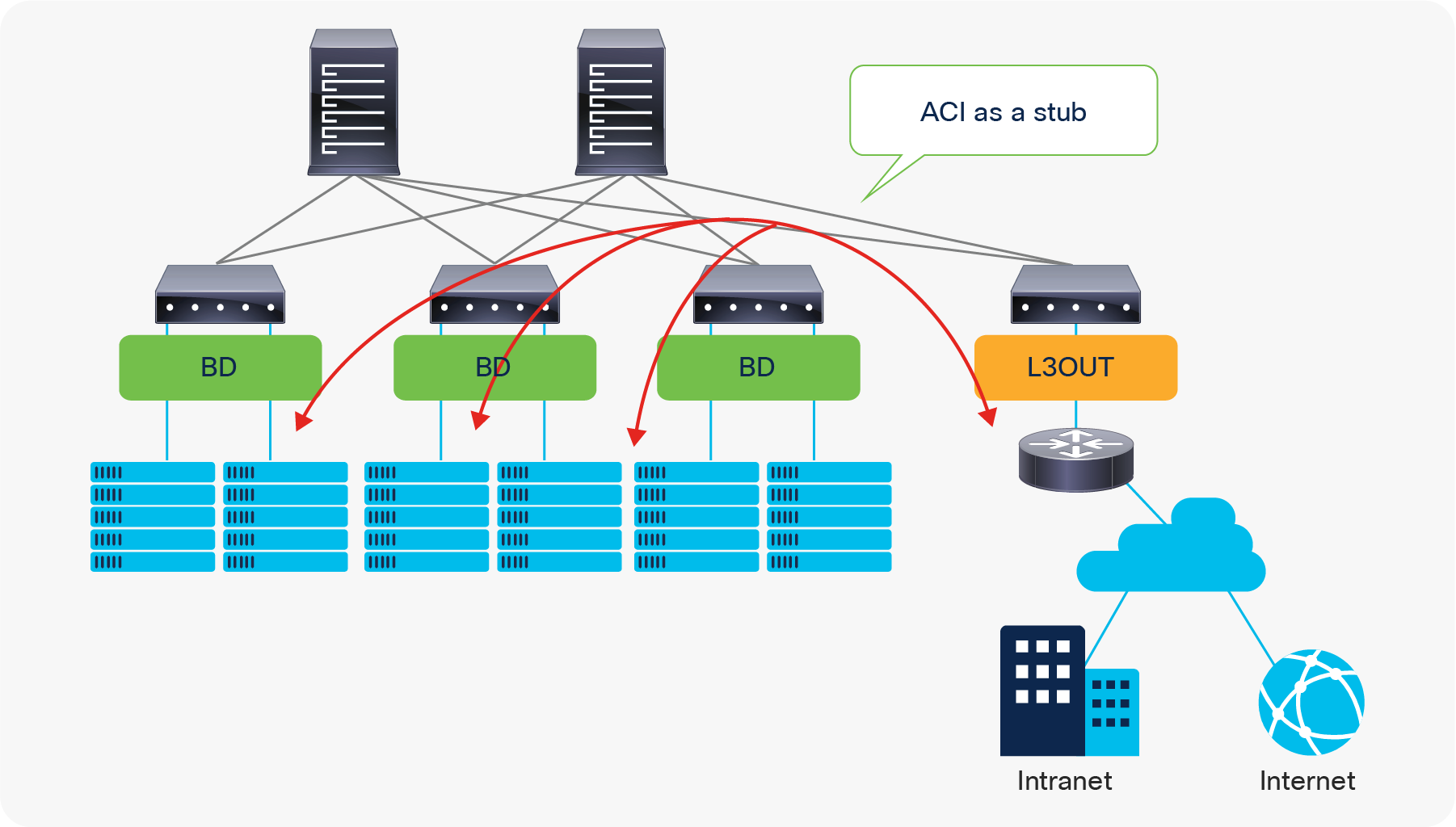
Due to this stub nature, traffic traversing from one L3Out to another through the ACI network was originally not supported.
Beginning with the APIC Release 1.1, however, Cisco ACI introduced the Transit Routing feature, which allows the ACI fabric to be a transit network so that traffic can traverse from one L3Out to another L3Out. Please refer to the “L3Out Transit Routing” section for details.
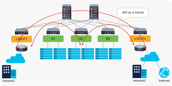
ACI fabric as a transit network
| Note: L3Out, essentially, connects a network device that has other subnets behind it. In ACI BD/EPG, every IP address is learned as an endpoint with /32 (or /128 for IPv6). Hence, connecting a network device that contains multiple subnets behind it to ACI via a BD/EPG will end up with an endpoint that has a huge number of /32-IP-addresses, which is not efficient and will likely hit a scalability limit. Please refer to the “L3Out and regular endpoints” section in the “ACI Fabric Endpoint Learning” white paper for this as well. |
The L3Out provides the necessary configuration objects for five key functions:
1. Learn external routes via routing protocols (or static routes)
2. Distribute learned external routes (or static routes) to other leaf switches
3. Advertise ACI internal routes (BD subnets) to outside ACI
4. Advertise learned external routes to other L3Outs (Transit Routing)
5. Allow traffic to arrive from or be sent to external networks via L3Out by using a contract
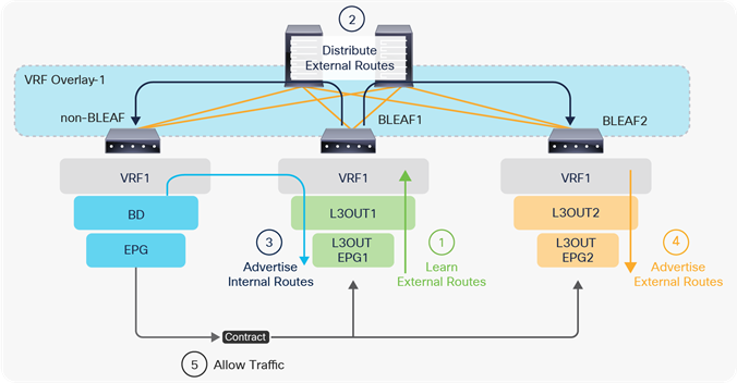
The five basic components of L3Out
In the following, each step is briefly explained. For detailed information about each step, please refer to later sections or the Cisco APIC Layer 3 Networking Configuration Guide.
1. Learn external routes on border leaf switches
Figure 4, below, depicts each component in an L3Out under a tenant (Tenant > Networking > External Routed Networks > L3Out). The parts in bold are the mandatory components to configure a routing protocol and learn external routes from an external network device. At least one L3Out EPG is also required to deploy a routing protocol and related interface parameters on leaf switches even though the L3Out EPG itself is a security construct like the EPGs, and is not a routing protocol configuration.
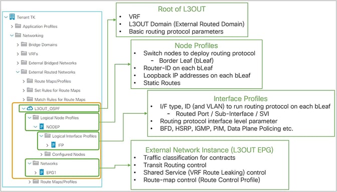
The basic components of L3Out in GUI (APIC 3.2 Release)
The following steps are the summary to deploy a routing protocol on an ACI border leaf with the components shown in Figure 4.
1. Root of L3Out
a. Select a routing protocol to deploy (such as OSPF or BGP)
b. Select a VRF to deploy the routing protocol
c. Select a L3Out Domain to define which range of VLANs and interfaces the L3Out configurations are allowed to use.
This domain itself is configured via Fabric Access Policies.
2. Node Profile
a. Select leaf switches on which the routing protocol is deployed.
(These are called border leaf switches)
b. Configure the Router-ID for the routing protocol on each leaf.
(Unlike a normal router, Cisco ACI does not automatically assign a Router-ID based on the IP addresses on the switch.)
3. Interface Profile
a. Configure leaf Interfaces on which the routing protocol runs.
This step consists of entering the following configurations: interface type (SVI, routed-port, or subinterface), interface ID, IP addresses, and so on.
b. Select a policy for the interface-level routing protocol parameters (such as hello interval).
In most deployments, the default configuration (policy) is used.
4. External EPG (L3Out EPG)
a. An empty external EPG is enough just to deploy a routing protocol and interface parameters such as IP address or SVI itself, and to establish routing protocol peering with neighbor routers.
Details on how to use external EPGs will be covered later.
The details on each component, such as the node profile or routing protocol options, are covered in later sections, such as “L3Out node and interface profiles” or “L3Out BGP”. Once the routing protocol is deployed on border leaf switches and a neighborship is established with external devices, those border leaf switches can learn external routes.
At this point, the external routes are only present on these border leaf switches and the ACI fabric has yet to distribute those routes to other leaf switches (See the next section, “Distribute external routes within the ACI fabric.”)
2. Distribute external routes within the ACI fabric
ACI uses Multi-Protocol BGP (MP-BGP) with VPNv4 in the ACI infra VRF (overlay-1 VRF) to distribute external routes from a border leaf to other leaf switches. Similar to other configurations/components in the ACI infra VRF such as ISIS between each switch, this configuration is also automated in the background. The only two configurations that users need to perform are as follows:
● Select the BGP AS number.
◦ This is the AS number to represent the entire ACI fabric. It is used for infra MP-BGP between leaf and spines, and for BGP in user L3Outs to establish BGP peers with external devices.
● Select spine switches as BGP Route Reflectors.
◦ Each leaf switch will be a BGP client for the selected route-reflector spine switches.
◦ This MP-BGP is per pod. Ensure that each pod has at least one route-reflector spine. Two route reflectors per pod is recommended.
◦ This Route Reflector for internal MP-BGP (VPNv4) and the External Route Reflector between pods for Multi-Pod MP-BGP (VPNv4, eVPN) are two different configurations.
Once these two components are configured under System > System Settings > BGP Route Reflector and assigned to Fabric Pod Profile under Fabric > Fabric Policies > Pods, the distribution of external routes will occur with MP-BGP, and the external routes will appear on non–border leaf switches as iBGP routes pointing to the border leaf switches TEP IP addresses (see Figure 5 and Figure 6). Please check the “Infra MP-BGP” section for more details.

ACI BGP AS number and MP-BGP route-reflector spines in APIC GUI (Release 3.2)
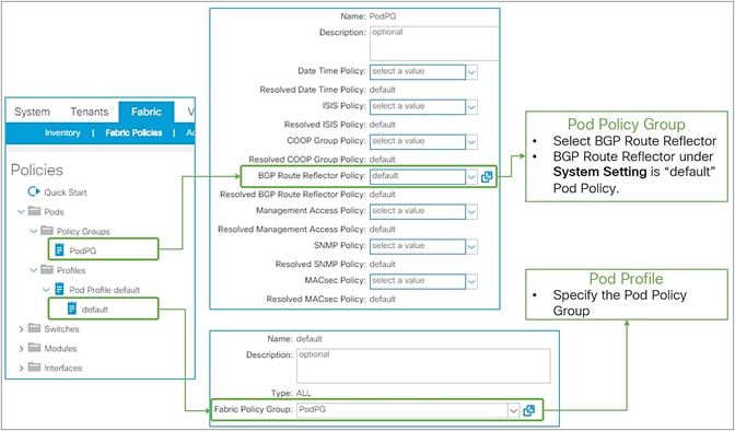
Pod Profile and Policy Group for BGP route reflector in APIC GUI (Release 3.2)
3. Advertise internal routes (BD subnets) to external devices
Once the MP-BGP route reflector policy is configured and assigned to a Pod Profile, all leaf switches should have external routes in their routing table for a given VRF. For external devices to have reachability to servers connected to ACI, ACI needs to advertise the BD subnets to outside.
Figure 7, below, depicts the summary of the most basic method to advertise a BD subnet, which is via associating a L3Out to the BD under Tenant > Networking > Bridge Domaine > BD > L3 Configurations tab.

Advertise internal routes (BD subnets) in GUI (APIC Release 3.2)
The key points here are as follows:
● Mark a BD subnet with an “Advertised Externally” scope.
● Associate the BD with the L3Out(s) that need(s) to advertise the BD subnet to the outside.
These two configurations internally create a route-map rule on the border leaf switches to redistribute the BD subnet (static/direct route) into the routing protocol of the associated L3Out.
If the BD happens to be deployed on the same border leaf, the redistribution happens via the route-map rule, and it will be advertised. However, that is usually not the case. Please remember that BD subnets are not distributed via MP-BGP, which is only for external routes. A contract between an EPG in the BD and the L3Out is required. Once the contract is configured, APIC knows the L3Out needs to talk to someone in the BD and installs the BD subnet on the border leaf switches. Then the redistribution happens with the route map mentioned above. Users typically do not need to pay attention to these details because a contract is required anyway to allow the traffic.
Please check the “ACI BD subnet advertisement” section for details.
4. Advertise external routes to other external devices (Transit Routing)
In case the communication needs to be between two L3Outs instead of a normal EPG, advertising external routes from one L3Out to another is required. This is called Transit Routing.
Advertising external routes to outside (Transit Routing) can be achieved with a single check box “Export Route Control Subnet” scope in L3Out Subnet (Tenant > Networking > External Routed Networks > L3Out > Networks > L3Out EPG > Subnets).
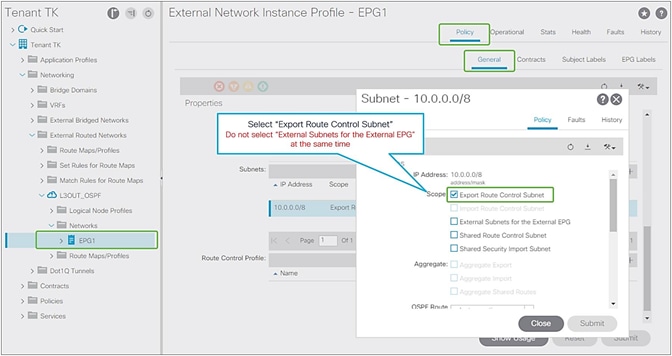
Export Route Control Subnet for Transit Routing GUI (APIC Release 3.2)
When this scope “Export Route Control Subnet” is selected, a route-map rule is created on the border leaf switches to redistribute the configured subnet (10.0.0.0/8 in Figure 8) from other L3Outs (routing protocol or static route) into the routing protocol for this L3Out. The redistribution happens from MP-BGP when the two L3Outs are on different border leaf switches. If the two L3Outs are on the same border leaf, redistribution happens directly between the routing protocols for each L3Out. If the two L3Outs use the same routing protocol on the same border leaf, other methods than redistribution are used.
Since the route-map rule uses an IP prefix-list, the subnet with “Export Route Control Subnet” scope needs to be exactly the same as what is in the routing protocol database. For example, 10.0.0.0/8 with “Export Route Control Subnet” scope exports only a route “10.0.0.0/8” but not 10.0.0.0/16. For aggregation/summarization, please check the “L3Out subnet scope options” section or the “L3Out Transit Routing” section for details.
Caution:
An external route with “Export Route Control Subnet” scope is advertised from the configured L3Out. This scope should not be configured on an L3Out that is learning the same route, because it would mean the L3Out tries to advertise the route back to its learning source. This could potentially cause a loop.
“External Subnets for the External EPG” scope, on the other hand, is to be configured on the L3Out that is learning the route. Hence, having these two scopes in the same L3Out is likely an undesired configuration. Please check step 5 below for details on “External Subnets for the External EPG” scope.
5. Allow traffic with a contract
The previous sections described the necessary configurations for the routing protocols to exchange routes between ACI and the external network. However, even if forwarding could theoretically work from a routing-table perspective, in ACI no traffic can flow across EPGs without a contract. This applies to L3Out EPG as well.
The key point here is how ACI classifies external routes to apply a contract. A normal EPG is classified based on a VLAN and a leaf interface from which the packet came in. In the case of L3Out, the classification of the traffic in the L3Out EPG is based on prefix matching. For this, the “External Subnets for the External EPG” scope on an L3Out subnet (Tenant > Networking > External Routed Networks > L3Out > Networks > L3Out EPG > Subnets) is used.
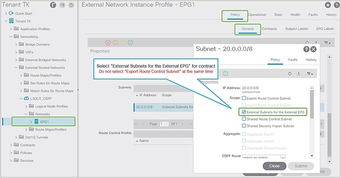
External subnets for the External EPG for contract in GUI (APIC Release 3.2)
Unlike the “Export Route Control Subnet” scope, the scope “External Subnets for the External EPG” does not have any impact on the routing table. It simply defines how to classify the traffic based on the source or destination IP address in order to apply a contract. Even when the routing table has only a default route 0.0.0.0/0, users still can configure more specific subnets, such as 20.0.0.0/8 with “External Subnets for the External EPG” under an L3Out EPG (EPG1 under Tenant > Networking > External Routed Networks > L3Out > Networks in Figure 9) and 30.0.0.0/8 with “External Subnets for the External EPG” under another L3Out EPG to apply a different set of contracts. This scope is not implemented with IP prefix-lists like “Export Route Control Subnet”. Hence, the matching is based on a longest prefix match (LPM). For example, a source for a packet with source IP 20.1.1.1 will be classified into L3Out EPG1 in Figure 9 due to 20.0.0.0/8 with “External Subnets for the External EPG” scope.
When a traffic IP does not match any of the subnets in the “External Subnets for the External EPG” scope in the VRF (please note that this scope is per VRF instead of L3Out; see the Caution below for details), the traffic will likely be dropped as there is no L3Out EPG with a contract in the VRF for the IP. If there is a 0.0.0.0/0 with “External Subnets for the External EPG” scope somewhere in the same VRF, that L3Out EPG with 0.0.0.0/0 will be the fallback for all traffic in that VRF, from a contract perspective.
Once the traffic classification is configured with “External Subnets for the External EPG” scope, users just need to configure a contract between the L3Out EPG and any components that need to communicate with the L3Out.
Please check the “L3Out subnet scope options” section or the “L3Out contracts” section for details.
Caution:
These L3Out subnet scopes are per VRF. Hence, even if a subnet 10.0.0.0/8 is learned from L3Out A, and traffic with source IP 10.0.0.1 is coming from L3Out A, the traffic could be classified into an L3Out EPG under L3Out B (let’s call it L3Out EPG B) if L3Out EPG B has 10.0.0.0/8 with “External Subnets for the External EPG” scope instead of L3Out EPG A, for some reason. This may depend on which leaf the contract rule is applied. One of the factors to decide which leaf applies the contract is Policy Control Enforcement Direction in the “L3Out contracts” section.
When the same subnet is configured with “External Subnets for the External EPG” scope in multiple L3Out EPGs in the same VRF, the configuration will be rejected. However, 0.0.0.0/0 is an exception. This does not mean 0.0.0.0/0 with “External Subnets for the External EPG” scope should be configured in multiple L3Out EPGs. It is strongly recommended NOT to do that to avoid traffic being allowed unexpectedly. See the “L3Out contracts” section for details.
This section covers the details on how Multi-Protocol BGP (MP-BGP) in the ACI fabric infra distributes the external routes learned from the L3Out to all leaf switches.
Figure 5 and Figure 6 in the previous section show the configuration (BGP AS and BGP route-reflector spines) in the APIC GUI for the infra MP-BGP. Once the configuration is done, the MP-BGP (the blue part in Figure 10) is deployed on the leaf and spine switches.
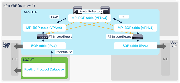
The following explains each component in Figure 10:
1. BGP IPv4/v6 Address Family (AF) is deployed on all leaf switches (both border and non–border leaf switches) in all user VRFs.
2. BGP VPNv4/v6 Address Family is also deployed on all leaf and route reflector spine switches in infra VRF (overlay-1 VRF).
a. All leaf switches establish iBGP sessions with route-reflector spine switches in infra VRF.
b. All leaf switches exchange their VPNv4/v6 routes through route reflector spines in infra VRF.
3. Once an L3Out is deployed on a leaf, the BGP IPv4/v6 AF on the same border leaf automatically creates a redistribution rule for all the routes from the routing protocol of the L3Out within the same user VRF.
a. This redistribution is called “Interleak”. If the L3Out is using BGP, no redistribution (interleak) is required for routes learned via BGP because the BGP process for the L3Out and for the infra MP-BGP is the same.
4. The redistributed IPv4/v6 routes are exported from the user VRF to the infra VRF as VPNv4/v6.
5. On other leaf switches, the VPNv4/v6 routes distributed through route-reflector spines are imported from the infra VRF to the user VRF as IPv4/v6.
a. On each leaf, BGP IPv4/v6 AF has export and import rules with the route target (RT) to exchange routes with VPNv4/v6 AF. The RT is in the form of “<ACI BGP AS>:<VRF VNID>”. This means that each VRF has the same RT on all leaf switches, and all VPNv4/v6 routes in the same VRF share the same RT. With this, a border leaf exports IPv4/v6 external routes into VPNv4/v6 AF with an RT, and each user VRF on other leaf switches can import VPNv4/v6 routes from its own VRF into IPv4/v6 AF based on the RT without incorrectly importing VPNv4/v6 routes from other VRFs.
| Note: Set rules can be applied to the route map for redistribution (interleak) from L3Out into BGP IPv4/v6 AF via an Interleak Route Profile. See the “Route Profile on Interleak” in the “L3Out Route Profile / Route Map” section for details. |
As described in the previous “Basic components of L3Out” section, the L3Out contains components called Logical Node/Interface Profile and Networks as its child objects. The details for each child component will be covered in each section later. Instead, this section covers the root component of L3Out.
In the root component of the L3Out, the most important configurations are VRF, external routed domain, and routing protocol.
● VRF
This is the VRF on which the L3Out and its routing protocol are deployed. This could be a VRF in the same tenant or a VRF in a common tenant.
● External routed domain
This is the domain to allow the L3Out to use a set of interfaces and VLANs. The domain itself is configured under “Fabric > Access Policies > Physical and External Domains > External Routed Domains” along with the VLAN pool and the Attachable Access Entity Profile (AEP).
● Routing protocol
This is the routing protocol that is deployed with the L3Out on the node and interface specified by the Logical Node/Interface Profile. Cisco ACI allows only one routing protocol per L3Out with one exception. BGP and OSPF can be configured in the same L3Out as an exception in order to be able to use OSPF as the IGP for BGP. Once the routing protocol is selected, some parameters such as OSPF area number or EIGRP AS number configurations show up in the same window. The details for each routing protocol parameters are covered in each routing protocol section later (BGP, OSPF, and EIGRP).
Although configurations other than the above three are optional, Figure 11 shows the GUI example for the L3Out root component followed by a quick description of each L3Out-specific option.
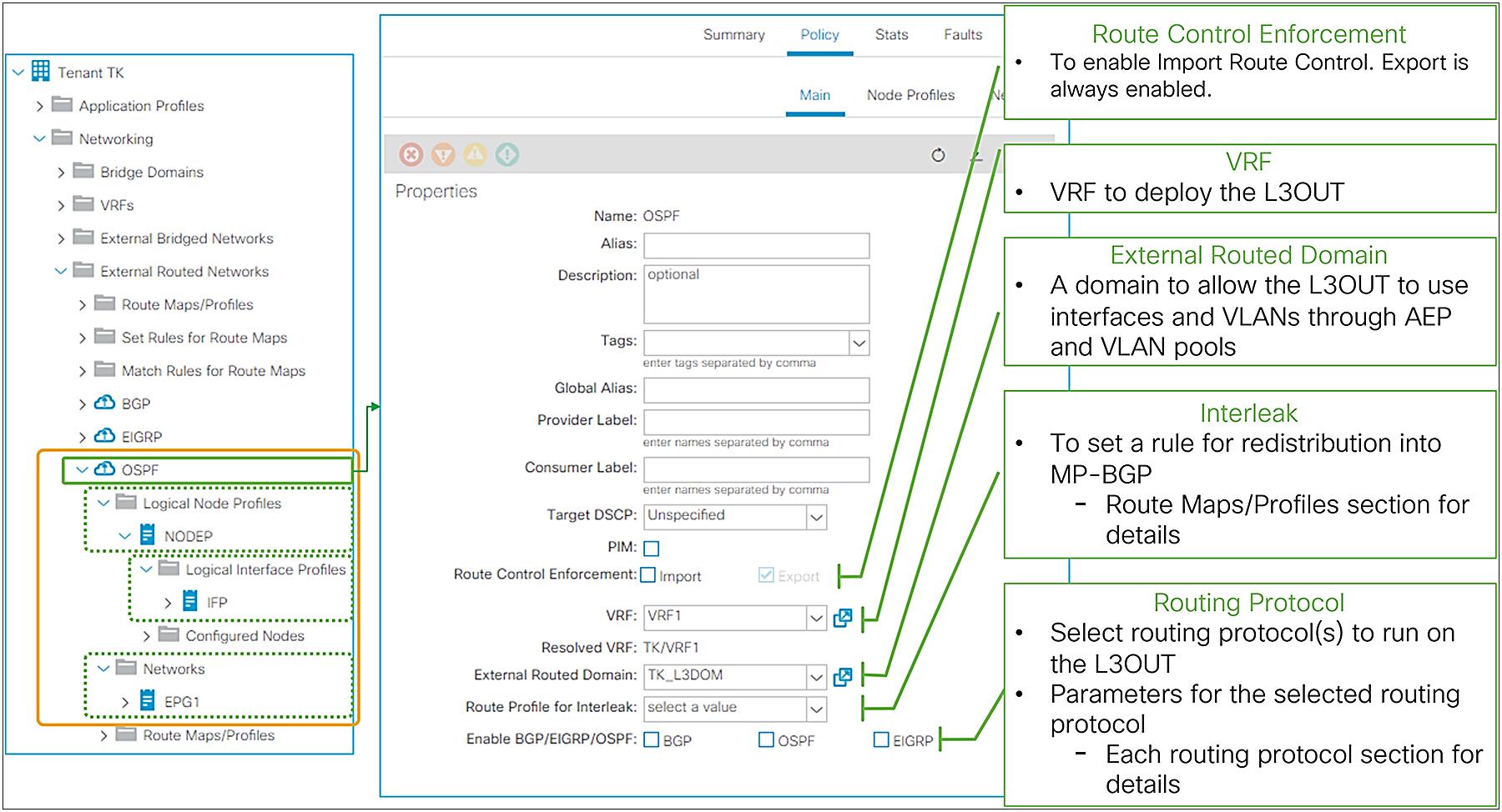
L3Out root component in APIC GUI (Release 3.2)
● Provider Label
This is for the GOLF (Giant OverLay Forwarding) feature. This label is to be configured on a GOLF L3Out in the infra tenant. Please check the “GOLF” section in the Cisco APIC Layer 3 Networking Configuration Guide.
● Consumer Label
This is also for the GOLF feature. This label is to be configured on an L3Out in a user tenant/VRF where it needs to communicate with external devices behind GOLF. This label must match the provider label for the GOLF L3Out in the infra tenant. It allows the L3Out in the user tenant/VRF to apply its L3Out EPG (L3Out Networks in GUI) to the GOLF L3Out. Please check the “GOLF” section in the Cisco APIC Layer 3 Networking Configuration Guide.
● PIM
This stands for Protocol Independent Multicast. Users may not need to manually toggle this option as it is typically configured on a VRF component, and this checkbox is automatically toggled when necessary. Please check the “IP multicast” section in the Cisco APIC Layer 3 Networking Configuration Guide for details.
● Route Control Enforcement
This is to enable Import Route Control, which allows users to configure Import Route Control Subnet scope for a subnet under the L3Out EPG (L3Out Networks in GUI). Please check the section L3Out subnet scope options for details.
● Route Profile for Interleak
This is to customize a route map that is used to redistribute external routes into the infra MP-BGP. Please check the subsection “Route Profile on Interleak” in the section “L3Out Route Profile / Route Map”.
L3Out Node and Interface Profiles
The main function of the L3Out Node and Interface Profiles is to specify which switch nodes should be border leaf switches and which interfaces should speak a routing protocol. Other functions for these two profiles are static routes, interface-level routing parameters, etc., as shown in Figure 12.
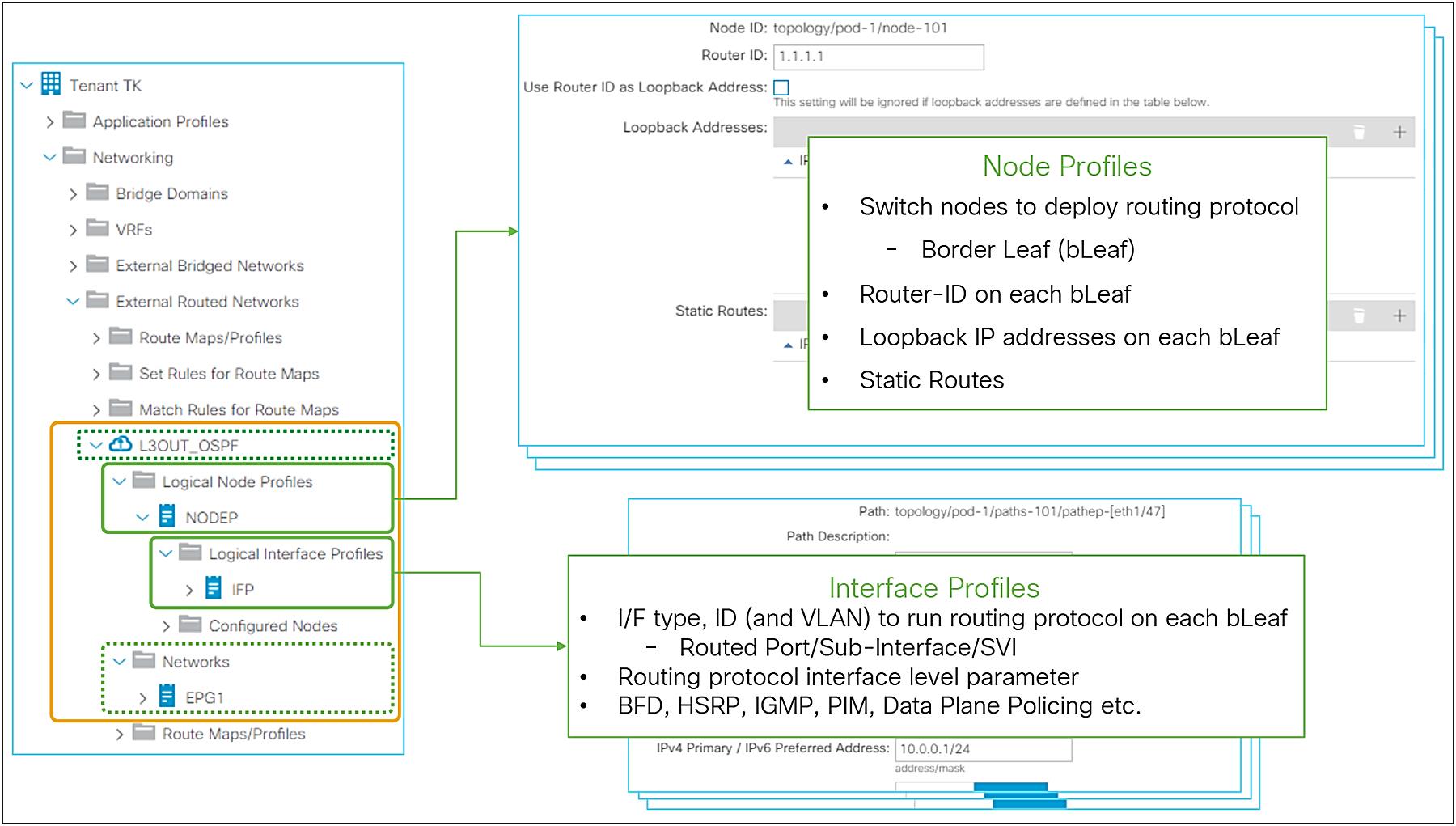
Logical Node Profiles / Logical Interface Profiles GUI (APIC Release 3.2)
Node and Interface Profiles Design
With Node and Interface Profiles, you can achieve the same configurations in multiple ways as long as the node IDs in the Node Profiles and Interface Profiles match.
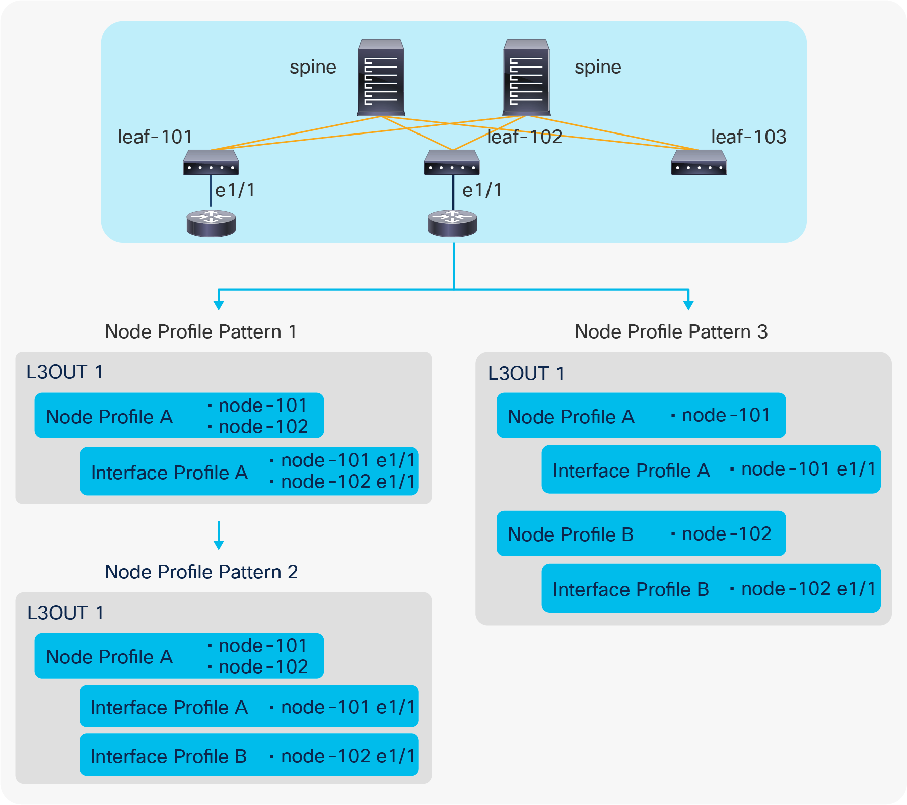
L3Out Node Profile configuration patterns
Figure 13 illustrates three different ways (here called “patterns”) to configure node-101 e1/1 and node-102 e1/1 to be part of the L3Out1 and speaking the routing protocol defined in L3Out1.
● Pattern 1: Both interfaces are in the same Logical Interface Profile A under a Logical Node Profile A.
● Pattern 2: Each interface is in its own Logical Interface Profile A and B under the same Logical Node Profile A.
● Pattern 3: Each interface is in its own Logical Interface Profile A and B under their respective Logical Node Profile A and B.
All these configuration patterns are correct and program the ACI border leaf identically.
| Note: When IPv4 and IPv6 addresses need to be configured on the same interface, the Logical Interface Profiles for IPv4 and IPv6 need to be different while the Logical Node Profiles can still be shared. |
This subsection goes through each option under the Logical Node Profile.
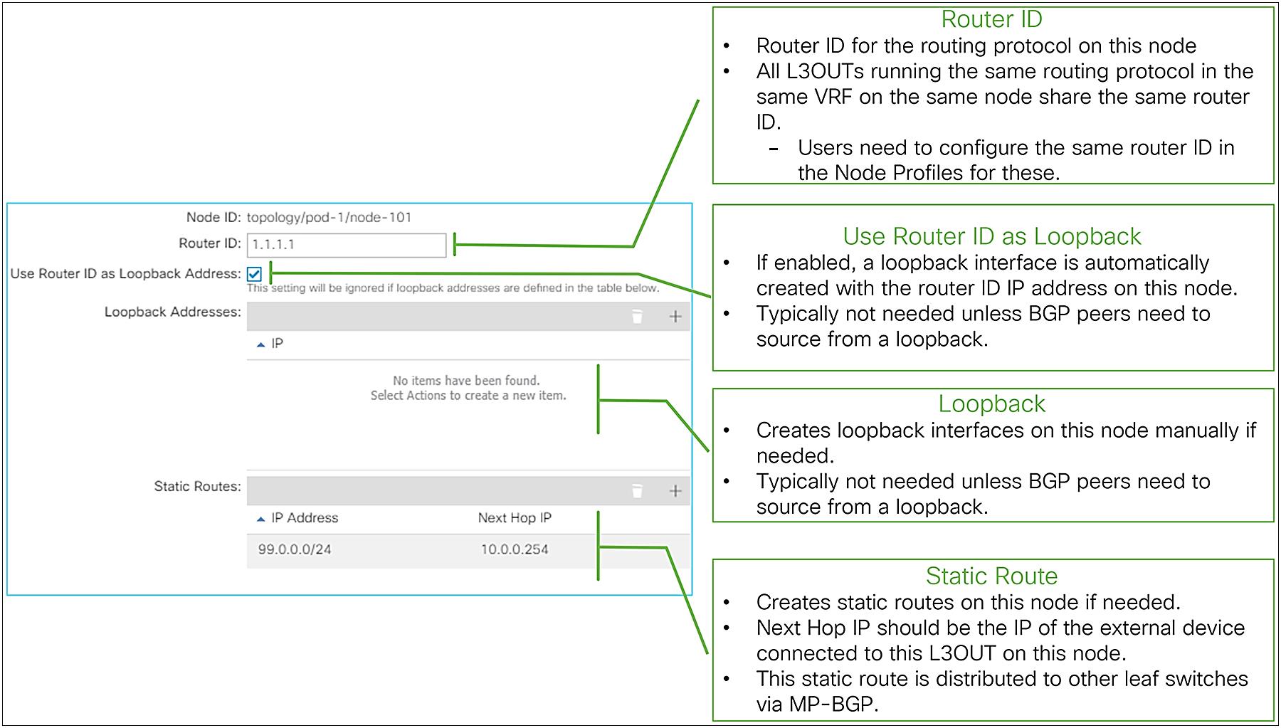
Logical Node Profile options in GUI (APIC Release 3.2)
● Node ID
This is a node ID where the routing protocol from the L3Out should be deployed. This node is called a border leaf.
● Router ID
This is a per-VRF router ID for the routing protocol defined in the L3Out on this node. The same principals of the router ID from a normal router apply to Cisco ACI as well.
This is equivalent to the following CLI if it were on a standalone Cisco NX-OS device. This is just for comparison and not an actual NX-OS–style CLI to configure on an APIC.
| router ospf default |
● Use Router ID as Loopback Address
Enable this option to create a loopback interface on this node with the router ID as its IP address. This is typically not required unless BGP peers need to source from a loopback with the router ID as their IP address.
This is equivalent to the following CLI if it were on a standalone NX-OS device. This is just for comparison and not an actual NX-OS–style CLI to configure on an APIC.
| router ospf default interface loopback10 |
This option is ignored when loopback interfaces are configured manually in the next option below.
● Loopback Addresses
This is to create loopback interfaces on this node manually with arbitrary IP addresses. This is typically not required unless BGP peers need to source from a loopback IP address.
● Static Routes
This is to create a static route on this node. The next-hop IP for the static route should be connected to a L3Out. When a next-hop IP is not configured, a static route with a null next-hop is created on the node.
A static route configured here is distributed to other leaf switches via infra MP-BGP, like external routes learned from a routing protocol.
Please check the section “L3Out static routes” for details.
| Note: If there are two L3Outs with the same routing protocol on the same node in the same VRF, the router ID on the Node Profiles on both L3Outs need to match. This is because using different router IDs in multiple L3Outs with the same routing protocol on the same node is equivalent to trying and entering the following two configurations on one standalone NX-OS device. router ospf default router ospf default Please note that these CLIs are just for comparison and are not actual NX-OS–style CLIs to configure on an APIC. |
Logical Interface Profile details
This subsection covers the main configuration options under the Logical Interface Profile.
Logical Interface Profile and Protocol Interface Profile in GUI (APIC Release 3.2)
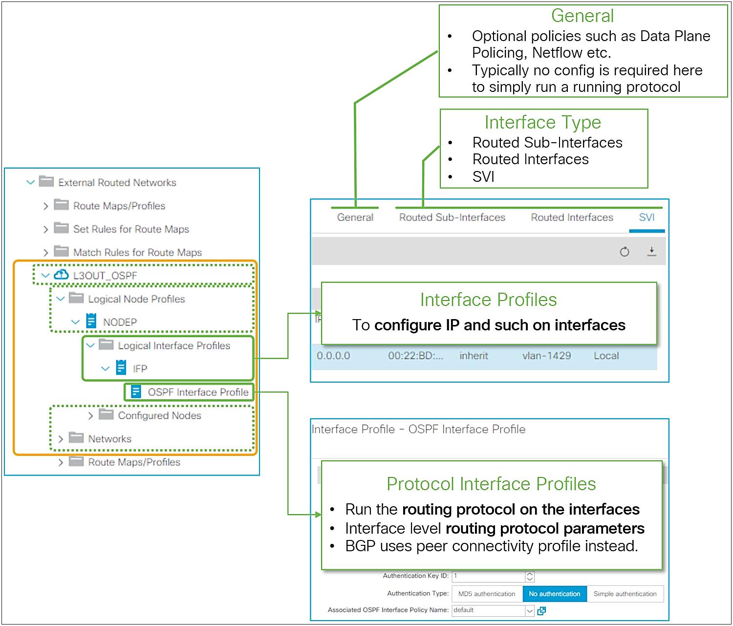
Figure 15 provides an overview of the options available in the Logical Interface Profiles. The main purpose of the Interface Profile is to create and configure interfaces to run the routing protocols on border leaf switches. This is similar to configuring an IP address and routing protocol commands such as ‘ip router ospf 1 area 0’ on a standalone NX-OS device. This is performed by configuring Interface Type (see Figure 15) and by configuring a Protocol Interface Profile. Without a protocol profile, the interfaces will not join the routing protocol (see each routing-protocol section for details: BGP, OSPF, and EIGRP). In addition to the Interface Type and the Protocol Interface Profile, one may need to configure the General tab in the Logical Interface Profile for optional interface-level features such as Data Plane Policing, NetFlow, PIM Interface Policy, Internet Group Management Protocol (IGMP), and so on. Bidirectional forwarding detection (BFD) can be configured under a Logical Interface Profile as well. See the “L3Out BFD” section for details on BFD.
The following paragraphs cover each Interface Type and its parameters. Please refer to the appropriate section for each routing protocol for details on the Protocol Interface Profile and other options.
The L3Out allows you to configure the following types of interfaces:
1. Routed Sub-Interface
2. Routed Interface
3. SVI
4. Floating SVI (introduced in APIC Release 4.2)
The design considerations related to the interfaces of an L3Out are almost the same as for a normal router or Layer 3 switch.
When a physical port is already used as a trunk port by an EPG, the same port cannot be used as a Routed Sub-Interface or a Routed Interface (L3 port) by an L3Out since the interface is already configured as a switchport (L2 port) by an EPG.
Figure 16 illustrates the meaning of the common parameters for a Routed Sub-Interface. Most of these parameters can also be found for the other interface types; the exception is the VLAN parameter, which can be configured for Routed Sub-Interfaces and for SVIs, but not for a Routed Interface.
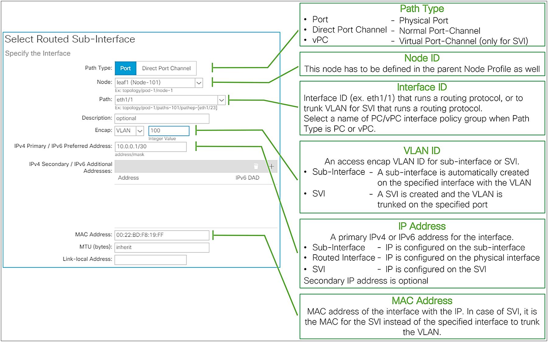
Logical Interface Profile common parameters
The following list provides additional details for each parameter type:
● Path Type
There are three Path types available in an L3Out, as shown in the following table:
| Path Type |
Description |
Supported I/F Type |
| Port |
a physical port such as eth1/1 on a single leaf switch |
Routed Interface |
| Direct Port Channel |
a normal port-channel on a single leaf switch |
Routed Interface* |
| Virtual Port Channel |
a vPC that spans across two leaf switches |
SVI |
● Node
This is to specify a border leaf for the interface. When selecting PC or vPC as the Path Type, this option is not available and not required since users need to select the name of a PC/vPC Interface Policy Group as a Path, and this configuration already includes the node information.
Ensure that the node ID here matches the one in the parent Logical Node Profile.
● Path
This is the interface ID, such as eth1/1 for Path Type Port, or the name of a PC/vPC Interface Policy Group for Path Type PC or vPC.
● Encap
This is the VLAN ID for the interface configured in the Path fields. This VLAN ID is sometimes referred to as encap or access-encap VLAN as opposed to some internal IDs such as PI-VLAN (Platform Independent VLAN). When an SVI is used, this VLAN ID needs to be included in the VLAN Pool under the External Routed Domain (L3Domain) associated to the L3Out. When a routed or subinterface is used, a VLAN Pool under the L3 Domain is not required.
◦ When a routed interface is used, this field is not required and does not appear.
◦ When a subinterface is used, a subinterface is created with this Encap VLAN.
◦ When an SVI is used, this Encap VLAN is trunked on the interface and an SVI for the VLAN is created on the specified leaf. Although various type of SVI configurations are supported such as one SVI with multiple trunk interfaces (Figure 17), when the same interface needs to trunk two different VLANs for two different SVIs, each SVI needs to be configured in different Logical Interface Profiles.
● IPv4 Primary / IPv6 Preferred Address
This is the main IP address on the subinterface, routed interface, or SVI. This IP address is used to peer with other routing protocol speakers.
● IPv4 Secondary / IPv6 Additional Addresses (optional)
This is useful to define additional IP addresses when a common IP is required on two border-leaf switches so that external devices can point to a single IP with a static route.
● MAC Address (optional)
This is a MAC address for the subinterface, routed interface, or SVI. In most cases, this field can be left as the default. For SVIs with the same VLAN ID, the same MAC address (default or non-default) must be used across ACI switches. This does not apply to SVIs across different L3Outs with SVI Encap Scope Local because those belong to different flooding domains even with the same VLAN ID.
● MTU (bytes) (optional)
This is the MTU (maximum transmission unit) value in bytes for the subinterface, routed interface, or SVI. This may need to be adjusted depending on the routing protocol, since the default “inherit” means that APIC configures the interface with the ACI default MTU of 9000 bytes. Most router interfaces do not use jumbo frames as a default, and routing protocols such as OSPF and EIGRP do not establish peering correctly unless the MTUs between the router interfaces match.
● Link-local Address (optional)
This is an IPv6 link-local address for the subinterface, routed interface, or SVI. By default, ACI creates an IPv6 link-local address from each leaf’s system MAC address in EUI-64 format.
| Note: The following command illustrates how to check the system MAC address of a leaf switch to calculate the IPv6 link-local address, if it is needed. leaf1# show sprom backplane | grep 'MAC Address' MAC Addresses : 01-23-45-67-89-ab |
| Note: In the case of an SVI, even though the IP address is configured per Path, this does not mean the SVI IP address needs to be configured per L2 interface. In case the same SVI and its IP address need to be deployed on multiple L2 interfaces, the configuration shown in Figure 17 will achieve that. |
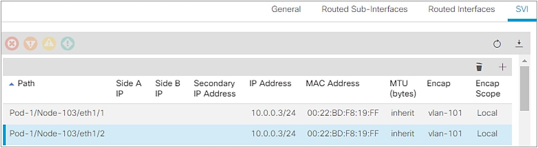
How to configure the same VLAN on two different Paths as an SVI
When an L3Out SVI is instantiated, Cisco ACI creates a bridge domain (BD) internally for the SVI to provide a Layer 2 flooding domain. This BD is called the L3Out BD or external BD, and is not visible to the user as a normal BD in APIC. An L3Out BD is created internally for each access-encap VLAN for an L3Out SVI while a normal BD can contain multiple access-encap VLANs all mapped to the same flooding domain. This L3Out BD may span across multiple border leaf switches if other border leaf switches also use the same access-encap VLAN for the L3Out SVI in the same L3Out.
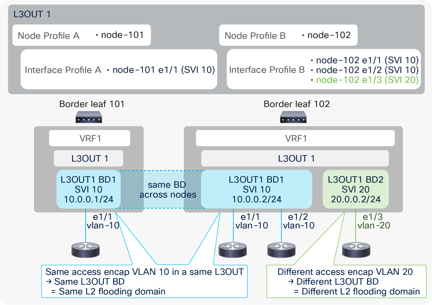
L3Out BD and access-encap VLAN (in the same L3Out)
In Figure 18, a single L3Out has two different access-encap VLANs, 10 and 20, with multiple Node and Interface Profiles. The picture shows that all three routers with the same access-encap VLAN 10 belong to the same L3Out BD1. This shows that the L3Out BD is independent of the Node Profile and the Interface Profile. The instantiation of the L3Out BD depends exclusively on the encap VLAN ID.
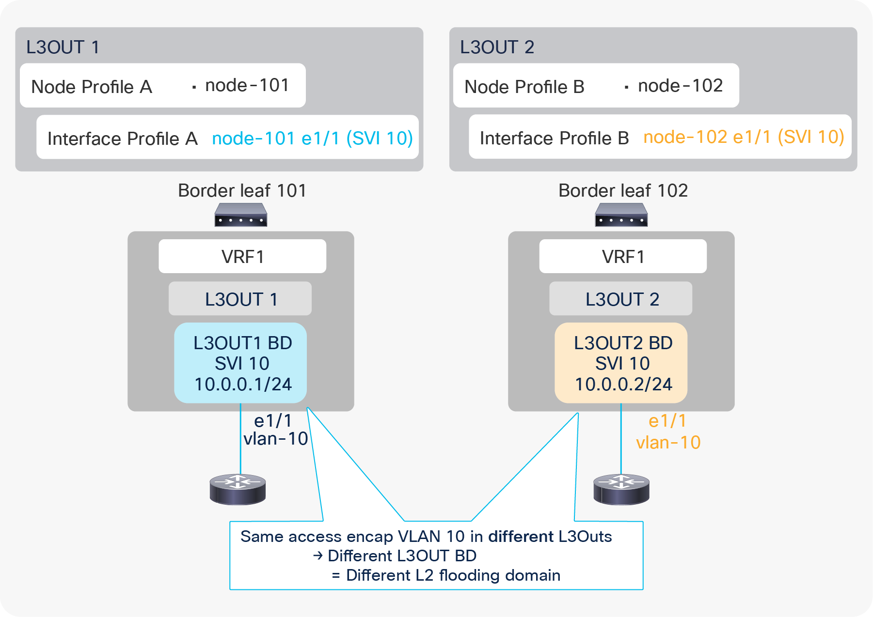
L3Out BD and access-encap VLAN (in different L3Outs)
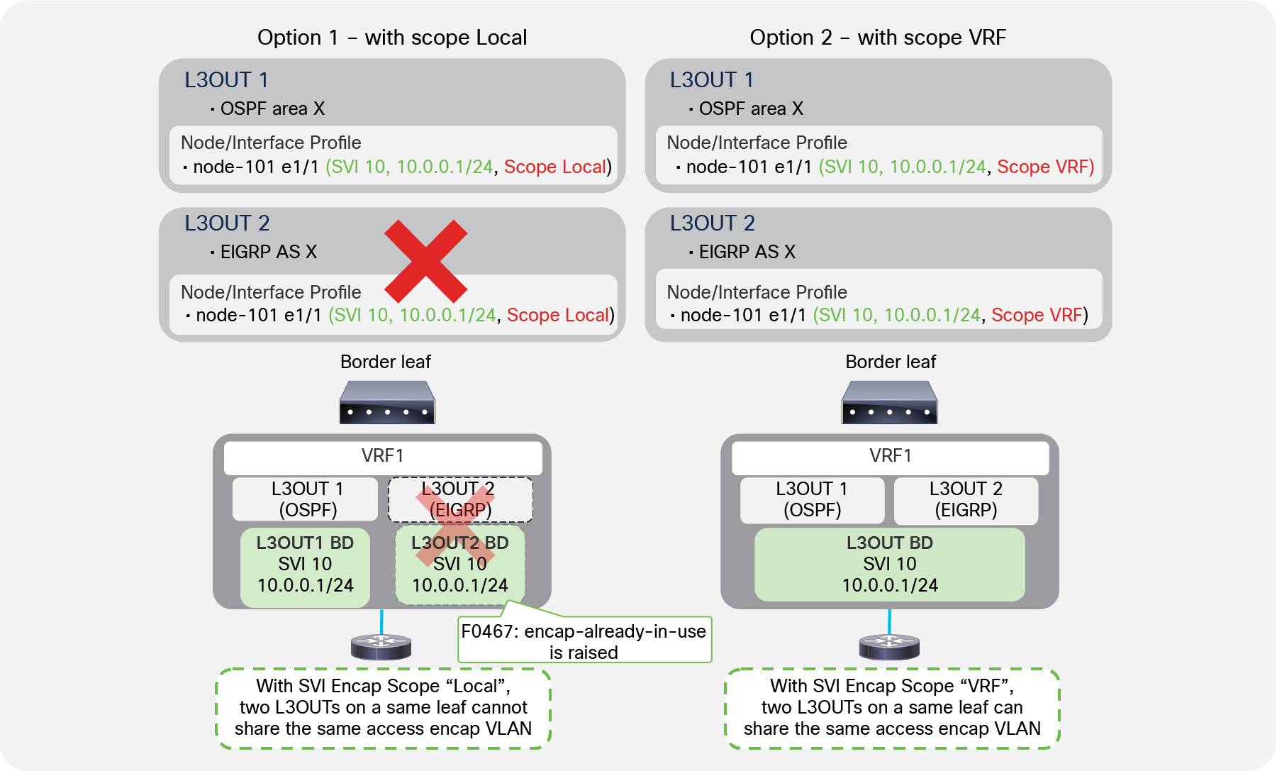
Figure 19 shows that an L3Out BD is created per access-encap VLAN within the L3Out. Even if two L3Outs use the same access-encap VLAN, each L3Out creates its own L3Out BD. Because of this, multiple L3Outs that use the same access-encap VLAN ID cannot coexist on the same border leaf. This behavior can be changed with the SVI Encap Scope option under the L3Out SVI.
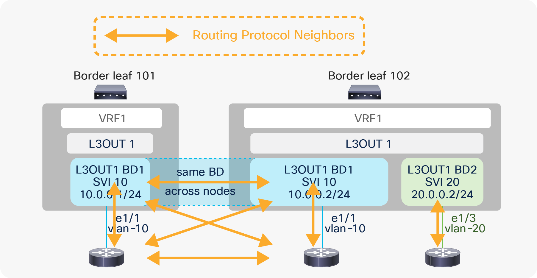
L3Out BD and routing protocol neighbors
Figure 20 shows that external routers connected to the same L3Out BD will exchange protocol hellos through ACI and become neighbors to each other on top of the ACI border leaf switches. However, if the routing protocol is BGP, this does not matter since a BGP peer is not limited within a Layer 2 domain.
The SVI Encap Scope option was introduced in APIC Release 2.3(1). This option is located under Tenant > Networking > External Routed Networks > L3Out > Logical Node Profiles > Logical Interface Profiles > SVI tab. The configurable options are “VRF” and “Local”. The default value is “Local”, which provides the same behavior as previous ACI releases, that is what was described in the previous subsection “L3Out bridge domain”.
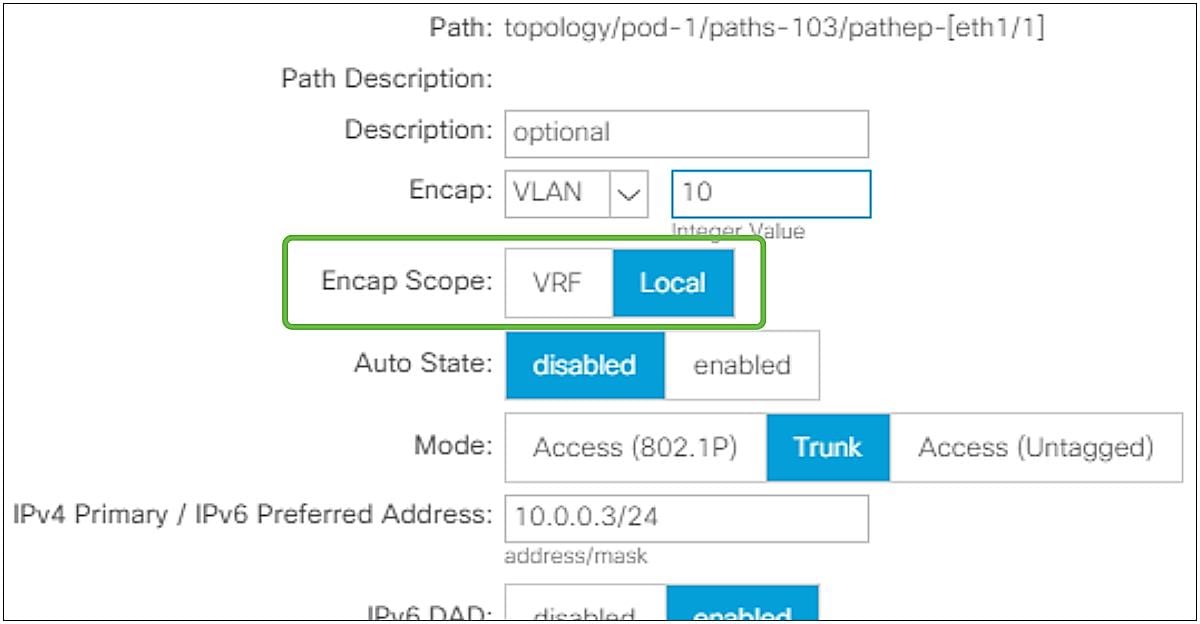
L3Out SVI Encap Scope in GUI (APIC Release 3.2)
SVI Encap Scope “VRF” allows multiple L3Outs in the same VRF to share an L3Out BD, which means to share the same access-encap VLAN even on the same leaf. The main scenarios of this feature are;
● Scenario 1: Multiple routing protocols on the same SVI on the same leaf
● Scenario 2: Granular route control over each BGP peer on the same leaf (by using a dedicated L3Out for each BGP peer)
Details of each scenario are explained below.
Scenario 1: Multiple routing protocols on a same SVI on the same leaf
Multiple routing protocols on a same SVI with SVI Encap Scope
As mentioned in the “L3Out bridge domain” subsection, by default or with SVI Encap Scope “Local”, each L3Out allocates an L3Out BD/SVI per access-encap VLAN. Hence, two L3Outs with the same access-encap VLAN cannot coexist on the same border leaf. In ACI, each L3Out can be configured only for one routing protocol. This means that by default one L3Out SVI on a given leaf cannot run multiple routing protocols. BGP and OSPF is an exception as ACI allows the configuration of OSPF and BGP in the same L3Out to provide IGP reachability for BGP.
With SVI Encap Scope “VRF”, it is possible to configure two routing protocols on the same leaf on the same interface for the same VLAN encapsulation by configuring the same SVI parameters, like the IP addresses on two L3Outs, as shown in Figure 22.
| Note: The Encap Scope “VRF” option also helps when two different OSPF areas need to be deployed on the same SVI on the same leaf switch, because you can now configure two L3Outs, one per OSPF area, on the same leaf and SVI. |
Scenario 2: Granular route control over each BGP peer on the same leaf
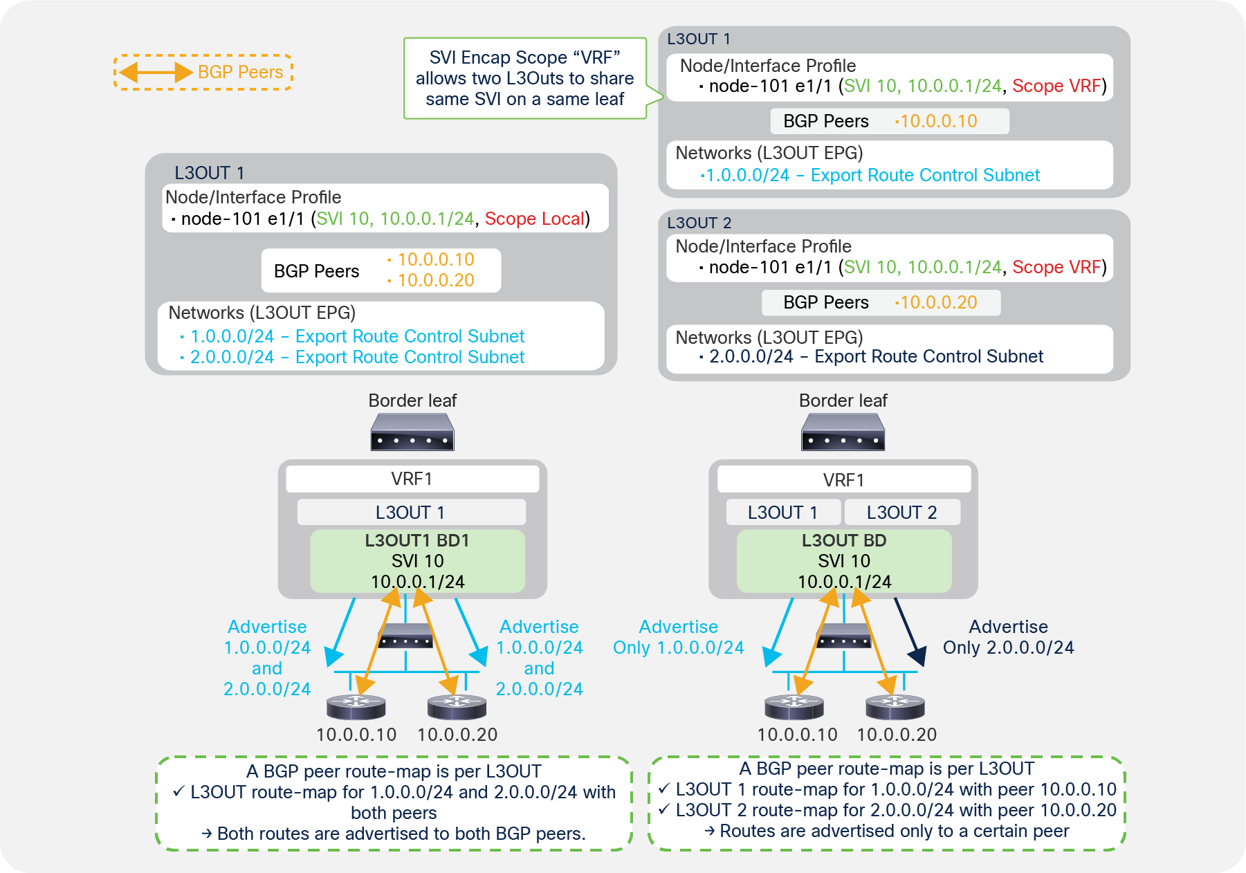
Regular BGP route control (left) and granular BGP route control with SVI Encap Scope VRF (right)
If you want to configure route control with BGP, you need to use the configuration called “Export Route Control Subnet”. This is a per-L3Out configuration. In the case of BGP, ACI internally creates a route map per each L3Out and per leaf, to apply the route-control policy configured on the APIC. See the “L3Out Transit Routing” section for details.
Because of this, when there are multiple BGP peers and different route-control policies need to be applied to each peer, a separate L3Out is required for each BGP peer. Creating an L3Out for each peer is not a problem when each BGP peer is connected to different border leaf switches. However, if all the BGP peers are connected to the same border leaf, by default, it is feasible only by using different VLANs/SVIs for each BGP peer. This is because it was not allowed to use the same access-encap VLAN on the same leaf for two different L3Outs.
Although having two different VLANs for each BGP peer may be doable, many times there are multiple BGP peers behind a single router or switch connected to a border leaf due to the nature of BGP peers that can be multi-hop L3 adjacencies, as Figure 23 shows. In such situations, it would be difficult to have two different VLANs for each BGP peer.
Starting with APIC Release 2.3(1) with an SVI Encap Scope “VRF” option, multiple L3Outs in the same VRF can share the same access-encap VLAN/SVI because an L3Out BD, which is per access-encap VLAN, can span across multiple L3Outs. As a result, multiple BGP L3Outs can be deployed on the same border leaf with the same VLAN/SVI so that different route-control rules can be used for each BGP peer behind the same VLAN/SVI (see the right side of Figure 23).
| Note: This route control per peer with SVI Encap Scope “VRF” option is only for BGP, because ACI creates a route map per VRF and per leaf for OSPF and EIGRP instead of per L3Out, as in BGP. See the “L3Out subnet scope options” or “L3Out Transit Routing” sections for details on route-control policy such as “Export Route Control Subnet”. |
| Note: For both scenarios 1 and 2, the SVI parameters such as IP and MTU for the same leaf need to be the same on both L3Outs. This is because the parameters must be applied on the same SVI on the border leaf, and there cannot be any conflicts. |
| Note: Scenario 2 (route control per BGP peers) can also be achieved with the feature “route map per BGP peer”, which was introduced in APIC Release 4.2(1). |
The SVI Auto State option was introduced in APIC Release 2.2(3) and 3.1(1). It is not available on 3.0(x). This option is located under Tenant > Networking > External Routed Networks > L3Out > Logical Node Profiles > Logical Interface Profiles > SVI tab. The option is disabled by default, which provides the same behavior as previous ACI releases.
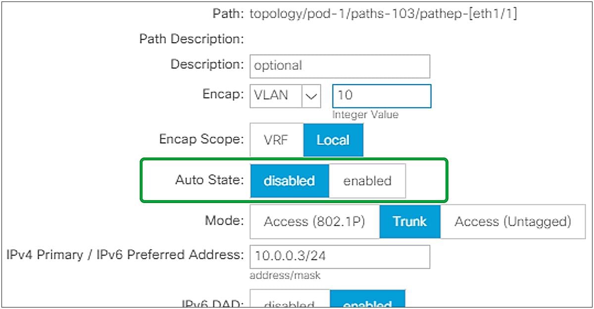
L3Out SVI Auto State in GUI (APIC Release 3.2)
In ACI, an SVI on a leaf is always up regardless of its VLAN member ports’ status. Although this is typically not a problem, it could pose a problem when using static routes. Enabling SVI Auto State allows a border leaf to bring an L3Out SVI down when all its VLAN member ports are down. The following is an example use case for SVI Auto State.
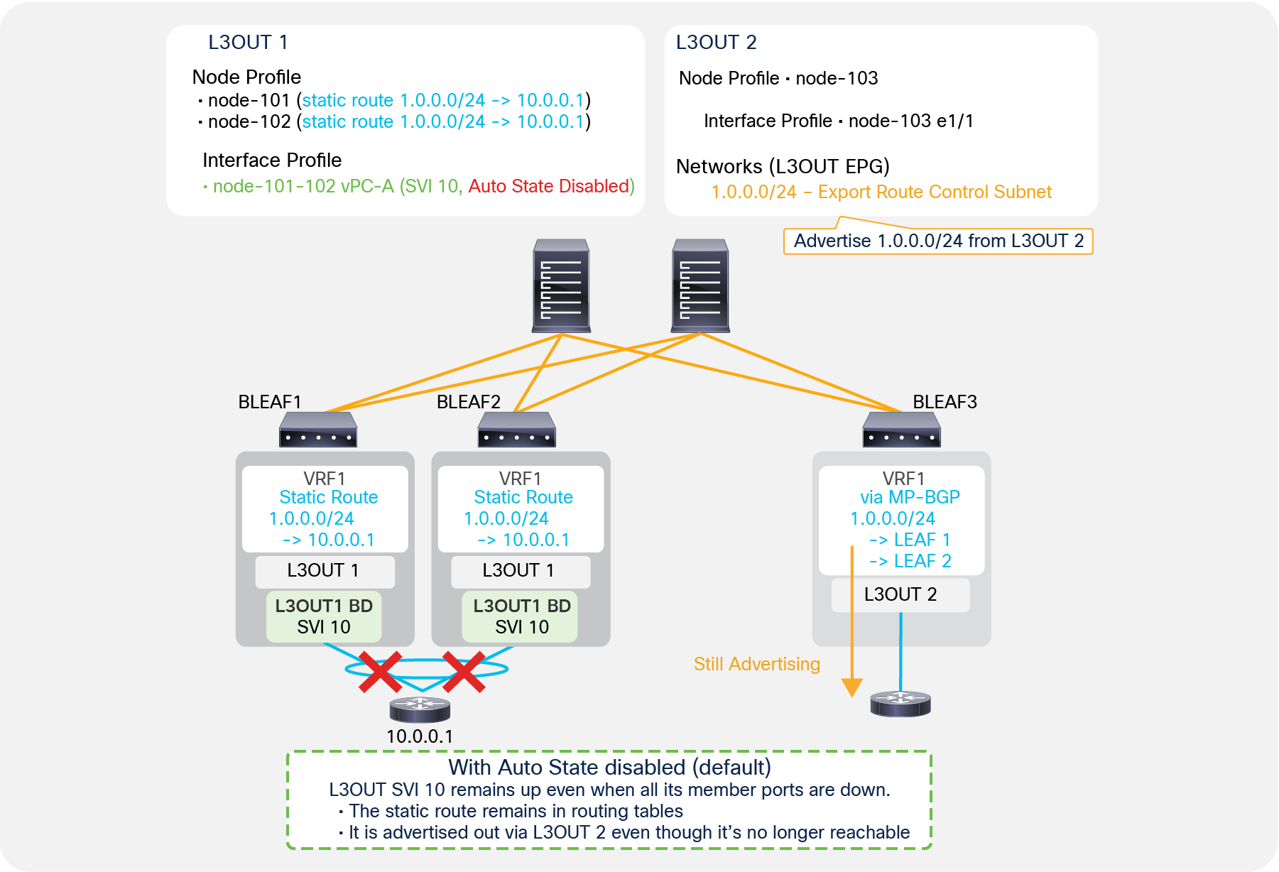
SVI Auto State disabled, with static route
Figure 25 shows a problem with static routes when SVI Auto State is disabled. L3Out 1 in Figure 25 has SVI 10 configured on border leaf switches 1 and 2 with vPC and SVI Auto State disabled. L3Out 1 also has static route 1.0.0.0/24 configured on both leaf 1 and leaf 2. L3Out 2 in Figure 25, on the other hand, is deployed on leaf 3 with “Export Route Control Subnet” for 1.0.0.0/24, which tries to redistribute 1.0.0.0/24 if it is in the routing table of leaf 3. In this situation, even if the vPC interfaces connected to the external router 10.0.0.1 on leaf 1 and leaf 2 go down, and there are no member ports for VLAN 10, the L3Out SVI 10 on both leaf 1 and leaf 2 remain up, because SVI Auto State is disabled. Hence the static route with a next-hop in the SVI 10 subnet remains in each routing table. Leaf 3 can still see the route received via MP-BGP, and it redistributes and advertises it out even though the ACI fabric no longer has any reachability for that route. One of the options to avoid this is to enable SVI Auto State on L3Out SVI 10.
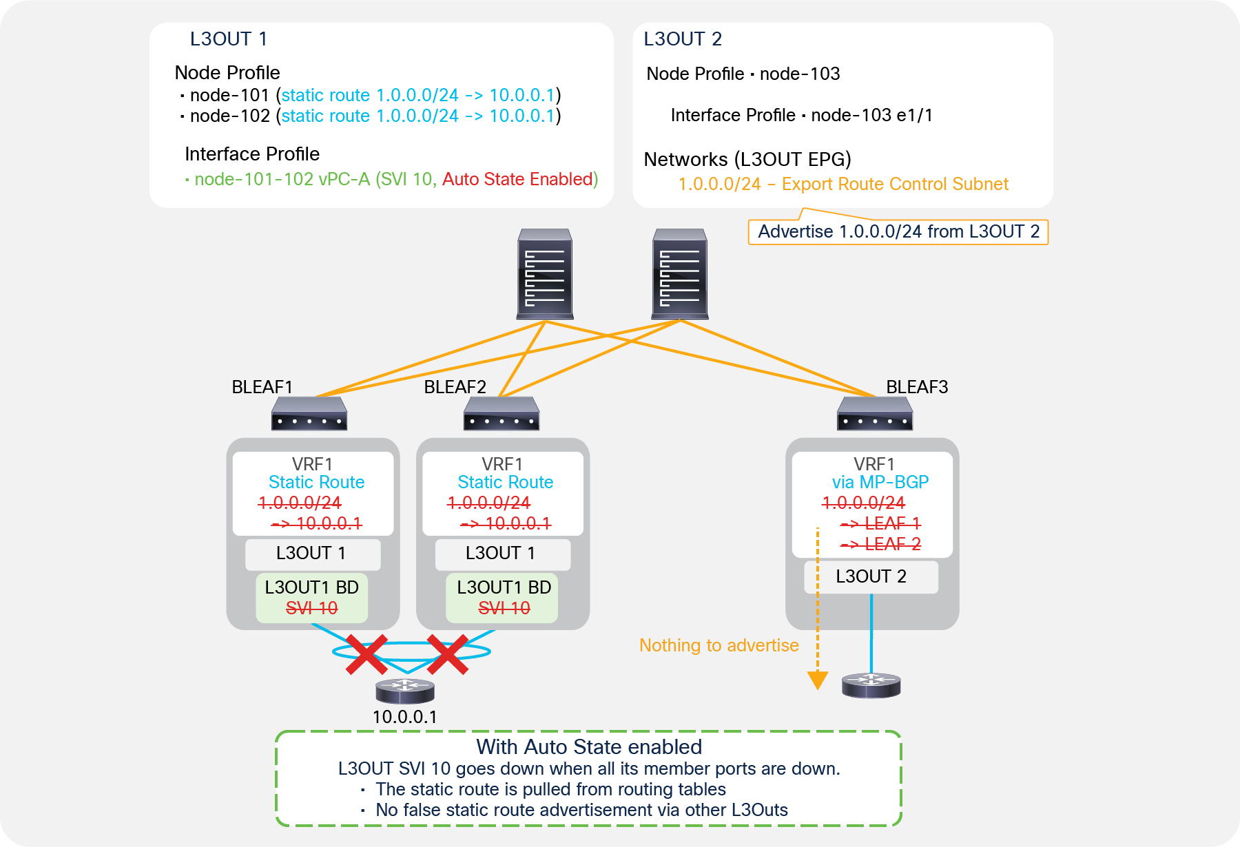
SVI Auto State enabled, with static route
Figure 26 shows how enabling SVI Auto State helps with the problem mentioned in Figure 25. When SVI Auto State is enabled and all the VLAN member interfaces (the vPC interfaces in Figure 26) go down, the L3Out SVI 10 on leaf 1 and leaf 2 also goes down. This results in leaf 1 and leaf 2 removing the static route with a next-hop in the SVI 10 subnet. Hence, leaf 3 no longer sees 1.0.0.0/24 via MP-BGP, and the redistribution and advertisement for an unreachable route stop.
| Note: The problem mentioned in Figure 25 can be avoided by using BFD for the static route as an alternative option to enabling SVI Auto State. |
| Note: When Auto State is enabled on the L3Out SVI with vPC, SVIs are brought down only when VLAN member ports on both the vPC pair of leaf switches are down. |
In Cisco ACI, static routes are configured as part of L3Out. Static routes are configured on each Logical Node Profile under “Tenant > Networking > External Routed Networks > L3Out > Logical Node Profiles > Node > Static Routes”. If only static routes are required without any dynamic routing protocols, users can leave the dynamic routing protocol checkbox on the root L3Out component blank and configure only the Logical Node Profile with Static Routes and the Logical Interface Profile. This still requires associating the VRF and the External Routed Domain on the root L3Out component.
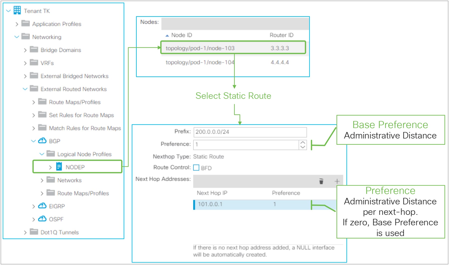
L3Out static-route configuration in GUI (APIC Release 3.2)
L3Out static route in GUI (APIC Release 4.1)
● Prefix
This is to configure a prefix itself for the static route.
● Preference (Base Preference)
This is to configure the administrative distance (AD) for the static route. The AD can be set either per static route or per next-hop. This preference option (right beneath the Prefix field) is to configure the AD to be used as a fallback in case a Preference for the next-hop IP address is not specified or zero.
● Route Control
This is to enable BFD (bidirectional forwarding detection) on the static route. Please refer to the “L3Out BFD” section for details.
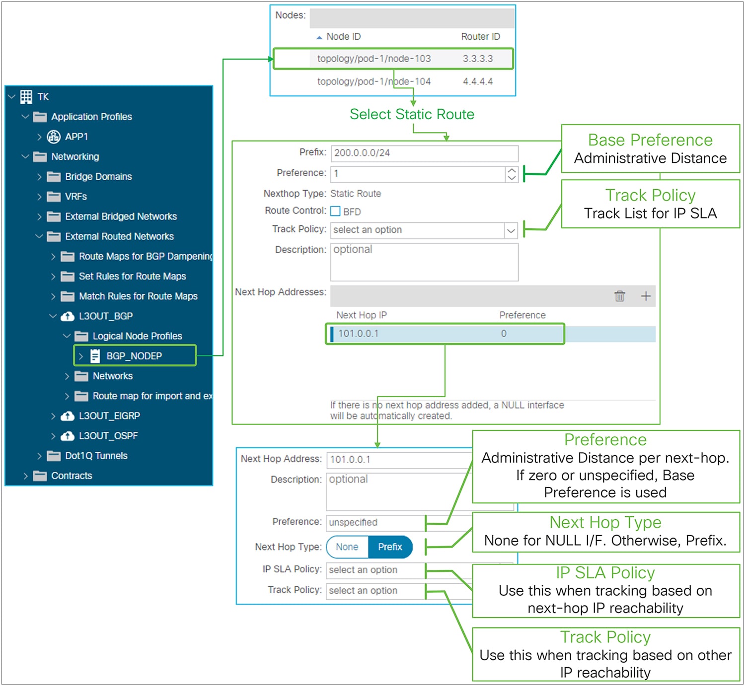
● Track Policy
This is for the IP SLA feature that was introduced from APIC Release 4.1(1). It sets a track policy that monitors the reachability of a group of IP addresses as an indicator of the validity of the static route. The tracking configuration can be performed in multiple ways or at multiple levels of granularity: as part of the static route or per next-hop address. The track policy at the static-route level (this field) retrieves information about the reachability of a set of IP addresses from the routing table, and if the reachability condition is met, the static route is kept in the routing table.
The validity of each individual next-hop can also be monitored separately with two similar configurations: an IP SLA Policy or a Track Policy under each Next Hop Address. The IP SLA policy for the next-hop address defines how to check the reachability of the next-hop itself (that is, which protocols to use). The track policy for next-hop address instead defines which IP addresses to check (other than the next-hop address itself) in order for the next-hop to be considered valid.
The Track Policy of the static route itself takes precedence when both the static route and each next-hop have Track Policy or IP SLA Policy. See the “IP SLA tracking for L3Out static routes” subsection, below, for details.
● Next Hop Addresses
This is to configure next-hop IP addresses for the static route. One or more next-hops can be configured for the same static route prefix. Beginning in APIC Release 1.2(2), a Null-0 next-hop is automatically created when there is no Next Hop Addresses entry configured.
◦ Next Hop IP
IP address to be used as a next-hop for the static route
◦ Preference
Administrative distance for this next-hop IP. If it is zero or unspecified, ACI uses the Base Preference to program the hardware.
◦ Next Hop Type
This can be either None or Prefix. None is for the NULL interface. Next Hop IP must be 0.0.0.0/0 for None. Prefix is to specify the actual next-hop IP instead of NULL (0.0.0.0/0).
This option was introduced in APIC Release 4.1(1) to have a NULL next-hop and non-NULL next-hops for one static route at the same time. Prior to Release 4.1(1), a static route could have either only a NULL next-hop or only non-NULL next-hops.
◦ IP SLA Policy
This option sets IP SLA policy directly on the next-hop IP instead of using a Track Policy. This is to track the next-hop availability by probing the next-hop IP itself instead of other IP addresses that are grouped and monitored by a track policy. When the SLA condition is not met, the next-hop is removed from the routing table.
A Next Hop Addresses entry can have either an IP SLA Policy or a Track Policy, not both.
The IP SLA Policy and the Track Policy were introduced from APIC Release 4.1(1). See the “IP SLA tracking for L3Out static routes” subsection for details.
◦ Track Policy
This configuration defines a group of IP addresses whose reachability is used by ACI to decide whether this next-hop entry for the static route should be kept in the routing table or not, instead of directly monitoring the next-hop IP. The monitoring of the IP addresses defined in the Track Policy is performed using the protocol defined in the IP SLA Policy nested in this track policy. When the reachability condition in the track policy is met, the next-hop is kept in the routing table.
A Next Hop Addresses entry can have either IP SLA Policy or Track Policy, not both.
The IP SLA Policy and the Track Policy were introduced from APIC Release 4.1(1). See the “IP SLA tracking for L3Out static routes” subsection for details.
IP SLA tracking for L3Out static routes
This feature was introduced in APIC Release 4.1(1). This feature checks the validity of an L3Out static route by probing a group of IP addresses. A track list defines which IP addresses to monitor. This list contains track members that consist of probe IP addresses and IP SLA method, and a threshold for a value that is calculated based on the status of each track member. Based on the threshold, a track list brings down or up the static route itself or the next-hop depending on where the configuration is attached. A track list can be attached to either the static route itself and/or to its next-hop, and the static route and/or the next-hop is kept in the routing table when a track list shows that there is enough reachability based on the threshold condition configured in the track list. When a track list is configured on both a static route and its next-hops, and the track list for the static route itself meets the threshold for the down condition, the entire static route is removed from the routing table regardless of the track list status of the next-hops of the static route.
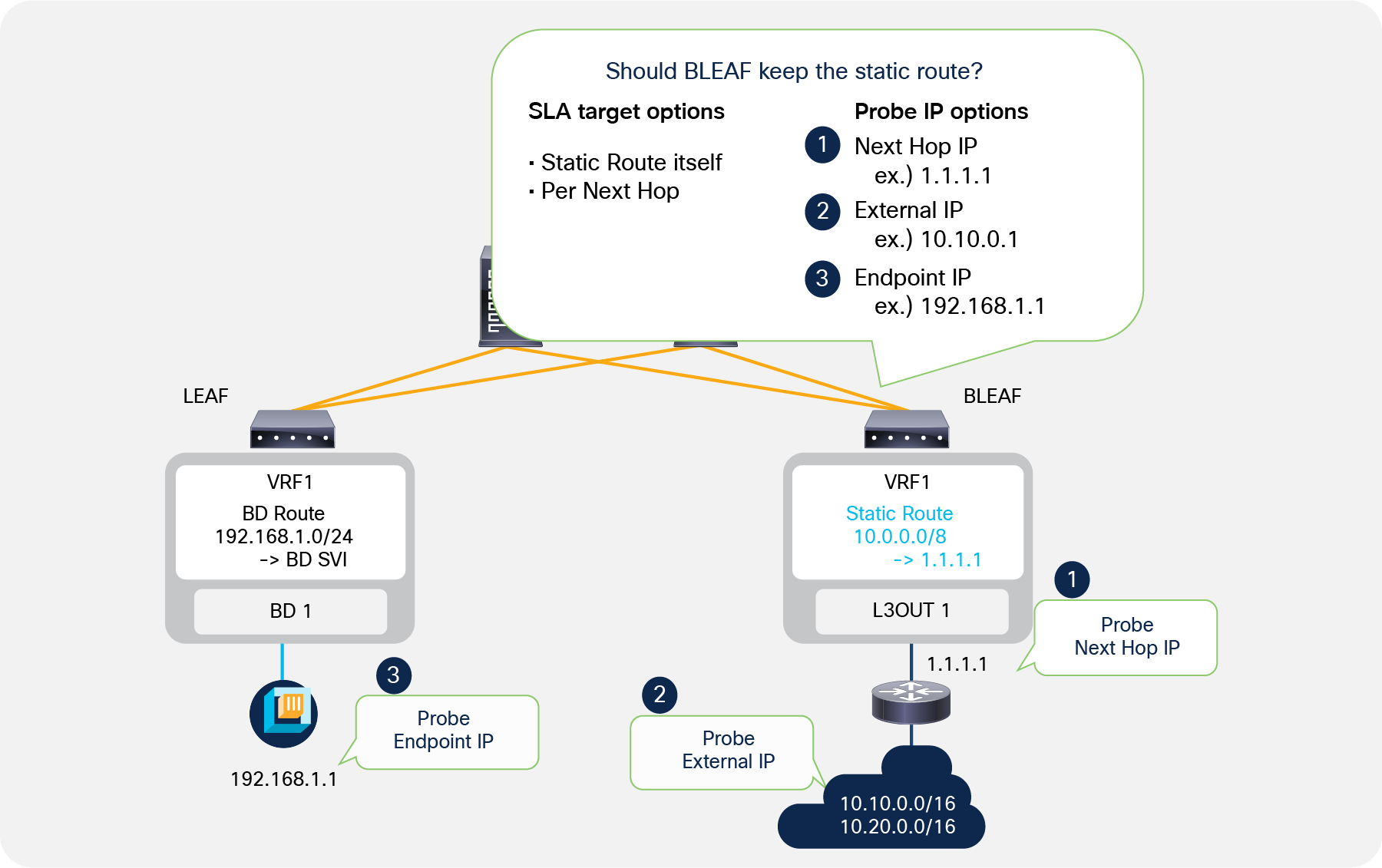
IP SLA for L3Out static routes
As Figure 29 depicts, ACI can probe the next-hop IP itself, external IPs, and endpoint IPs that may be relevant for the static route.
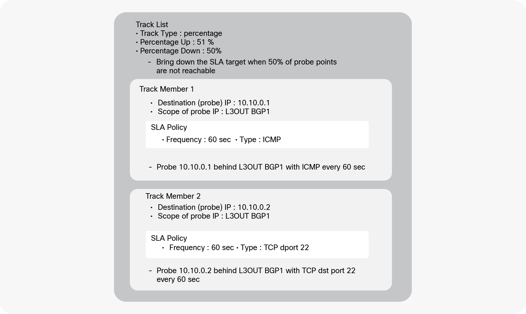
Example of a track list (IP SLA) for L3Out static routes
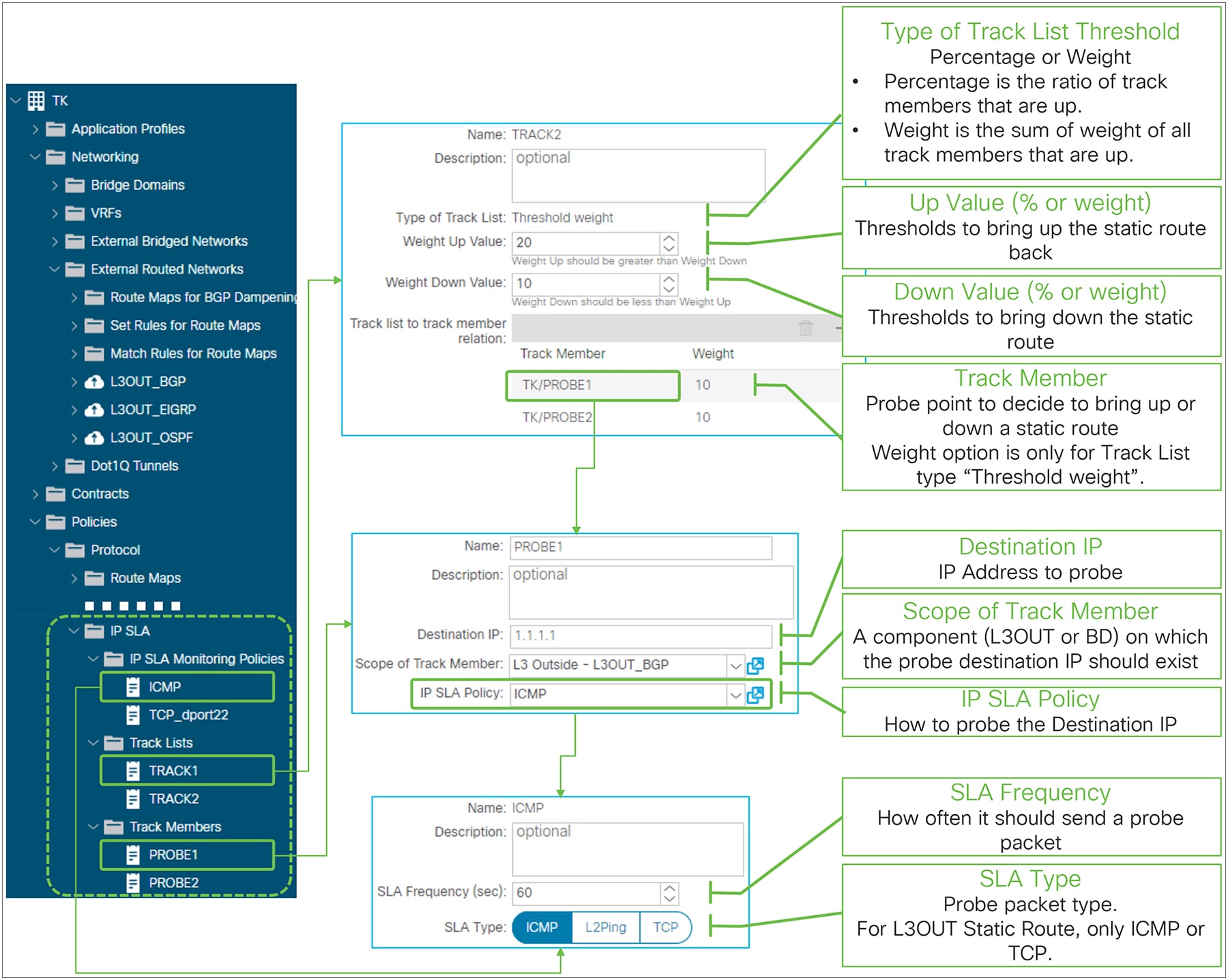
Figure 30 is an example of track list components and configuration. This track list has two track members (probe IPs). One is for the external IP 10.10.0.1 behind L3Out BGP1 (this is configured as scope of the track member in the APIC GUI) with ICMP as the protocol used by the probing traffic, which is sent every 60 seconds. Another is for the external IP 10.10.0.2 behind L3Out BGP 1 with TCP destination port 22 as the probing traffic sent every 60 seconds. As for the threshold condition, this track list uses percentages, with Up 51 percent and Down 50 percent. This means the track list is marked as down when only 50 percent of the track members are up. In this example, if one of the track members becomes unreachable, the percentage goes down to 50 percent, and the track list is marked as down. When the ratio of track members that are up reaches 51 percent, the track list is marked as up again. In this example, if both track members become reachable again, the percentage goes up to 100 percent, and the track list is marked as up again.
This track list needs to be attached to either a static route or its next-hop configurations to take effect. In order to associate the track list to a static route or to a next-hop, the Track Policy field is used in the static route or its next-hop configurations.
IP SLA (Track List) for L3Out Static Route in GUI (APIC release 4.1)
Track Lists
● Type of Track List threshold
This can be either Percentage or Weight. This parameter cannot be changed once a track list is created.
Percentage This is the ratio of the reachable track members over the total number of members.
Weight This is the sum of the weights for the reachable track members.
● Up Value (percentage or weight)
When the percentage or weight reaches this value, the track list is marked as up if it was down prior to this. Static routes or next-hops using the track list will be brought back up in the routing table accordingly.
● Down Value (percentage or weight)
When the percentage or weight reaches this value, the track list is marked as down if it was up prior to this. Static routes or next-hops using the track list will be brought down in the routing table accordingly.
Track Member (probe IP)
The track member is the configuration that defines an IP to which ACI sends a probe, which protocol should be used to verify the reachability of this IP, and where (L3Out, BD, etc..) ACI should try and reach the track member.
● Destination IP
The target IP address to probe. It can be the next-hop IP of the static route, an external IP, or an endpoint IP.
● Scope of Track Member
The component (L3Out or BD) on which the destination IP should exist.
● IP SLA Policy
The IP SLA Monitoring Policy that defines how to probe the destination IP in terms of which protocol to use and/or which L4 port.
IP SLA Monitoring Policy
● SLA Frequency (sec)
The frequency in seconds to probe the track member IP. The default value is 60 seconds.
● SLA Type
The type that defines which protocol is used for the probing packet. For an L3Out static route SLA, the supported options are ICMP or TCP with destination port.
| Note: Configuring an IP SLA policy or a track list on a next-hop under an L3Out static route are functionally equivalent. The IP SLA policy on a next-hop is just a shortcut where APIC internally creates a track list with one track member with the next-hop IP as the probe IP (destination IP) and the IP SLA policy. This is equivalent to manually configuring the track list and associating it to the Track Policy. |
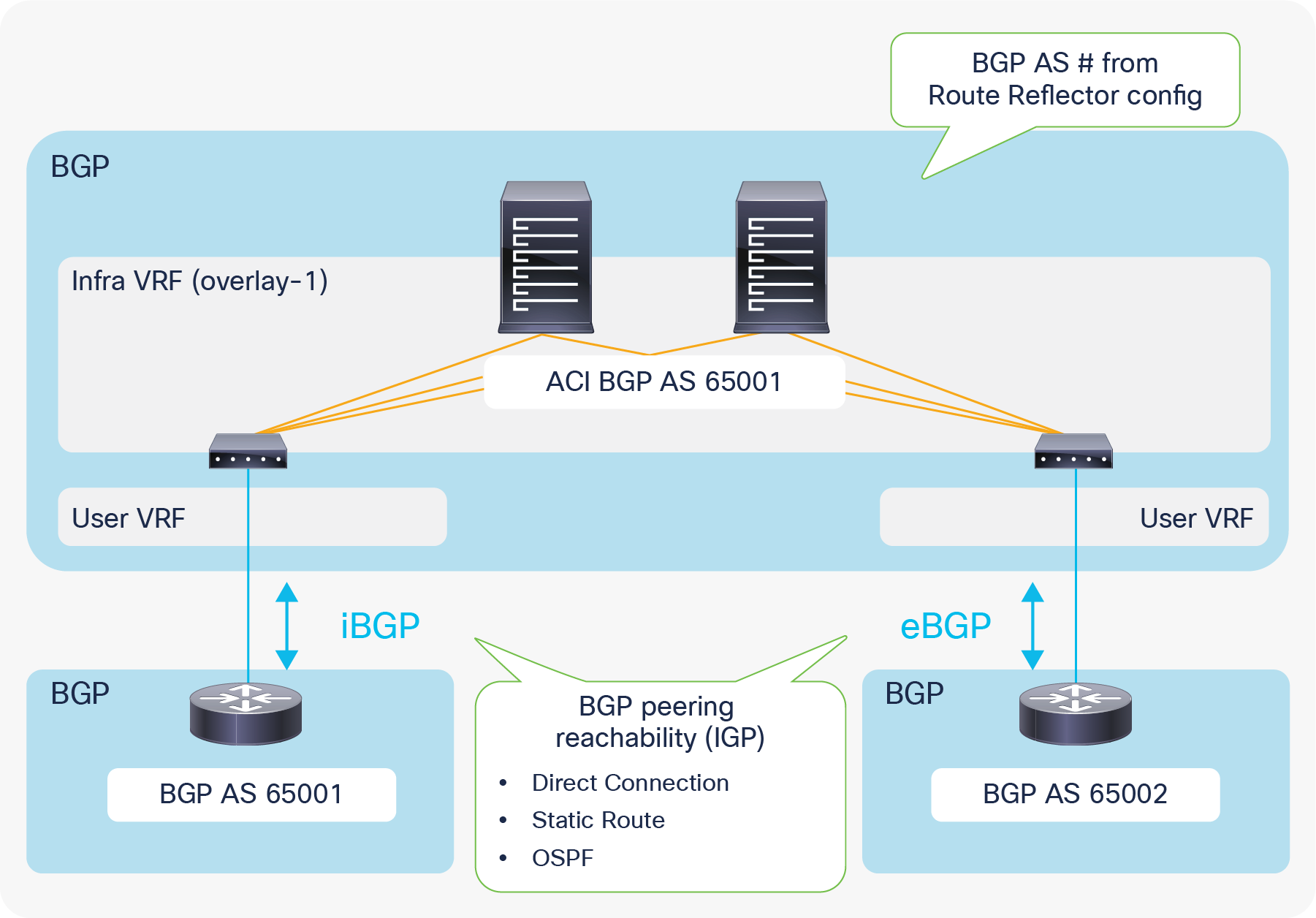
L3Out requires infra MP-BGP in which users configure route reflectors and the BGP AS number. This BGP AS number for infra MP-BGP is the ACI BGP AS, and an L3Out with BGP automatically belongs to the same BGP AS. Hence, external devices need to peer with the ACI BGP AS (as shown in Figure 32) unless ACI uses a local-as configuration in the BGP Peer Connectivity Profile to make its BGP AS look like something else to the peer. EBGP connectivity support was added beginning with APIC Release 1.1(1).
The supported method/IGP for BGP peering IP reachability for both iBGP and eBGP is as follows:
● Direct connection
● Static route
● OSPF
Supported source interfaces for BGP peering for both iBGP and eBGP are as follows;
● Loopback interface in Logical Node Profile
● Routed Interface, Routed Sub-interface, and SVI in Logical Interface Profile
| Note: A BGP session will be sourced only from a primary IP address of each interface even when secondary IP addresses are configured on the interface. |
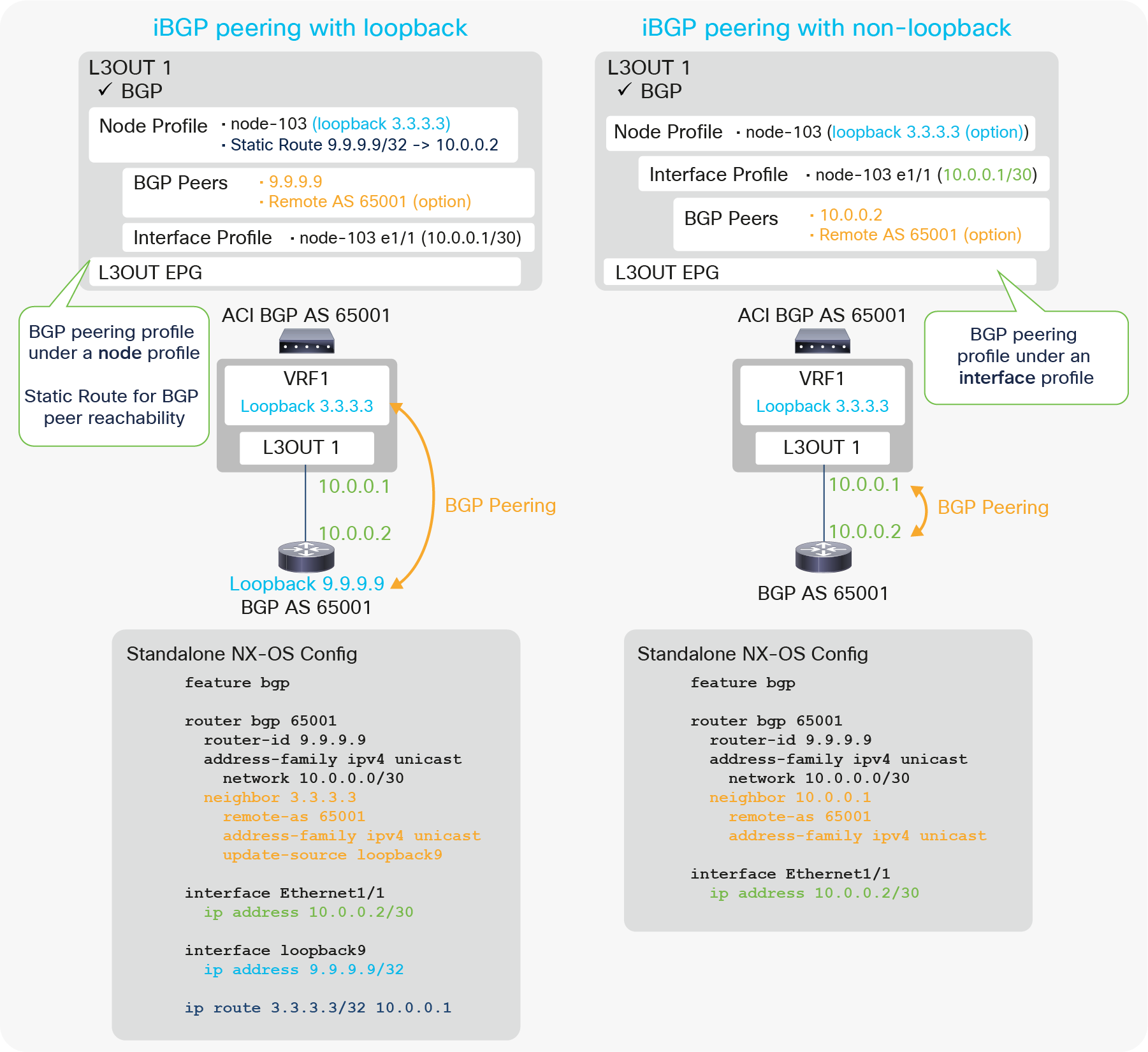
Figure 33 illustrates configuration examples for iBGP with peering on loopback and non-loopback interfaces. The key components to configure BGP in an ACI L3Out are the following:
● Enable BGP on the root of the L3Out.
● Configure BGP Peer Connectivity Profiles.
◦ Source is loopback: Configure under the Node Profile.
◦ Source is non-loopback: Configure under the Interface Profile.
● Configure static route (or OSPF) for BGP peer reachability.
◦ This is only when the peer is multiple-hops away, as in the case of loopback peering.
Just as with any other L3Out configuration, users need to associate VRF and External Routed Domain on the L3Out root as well.
| Note: The BGP Peer Connectivity Profiles contain many options. However, the minimum iBGP configuration just requires the neighbor IP address. For details on other options, please see “BGP protocol options” in this section. |
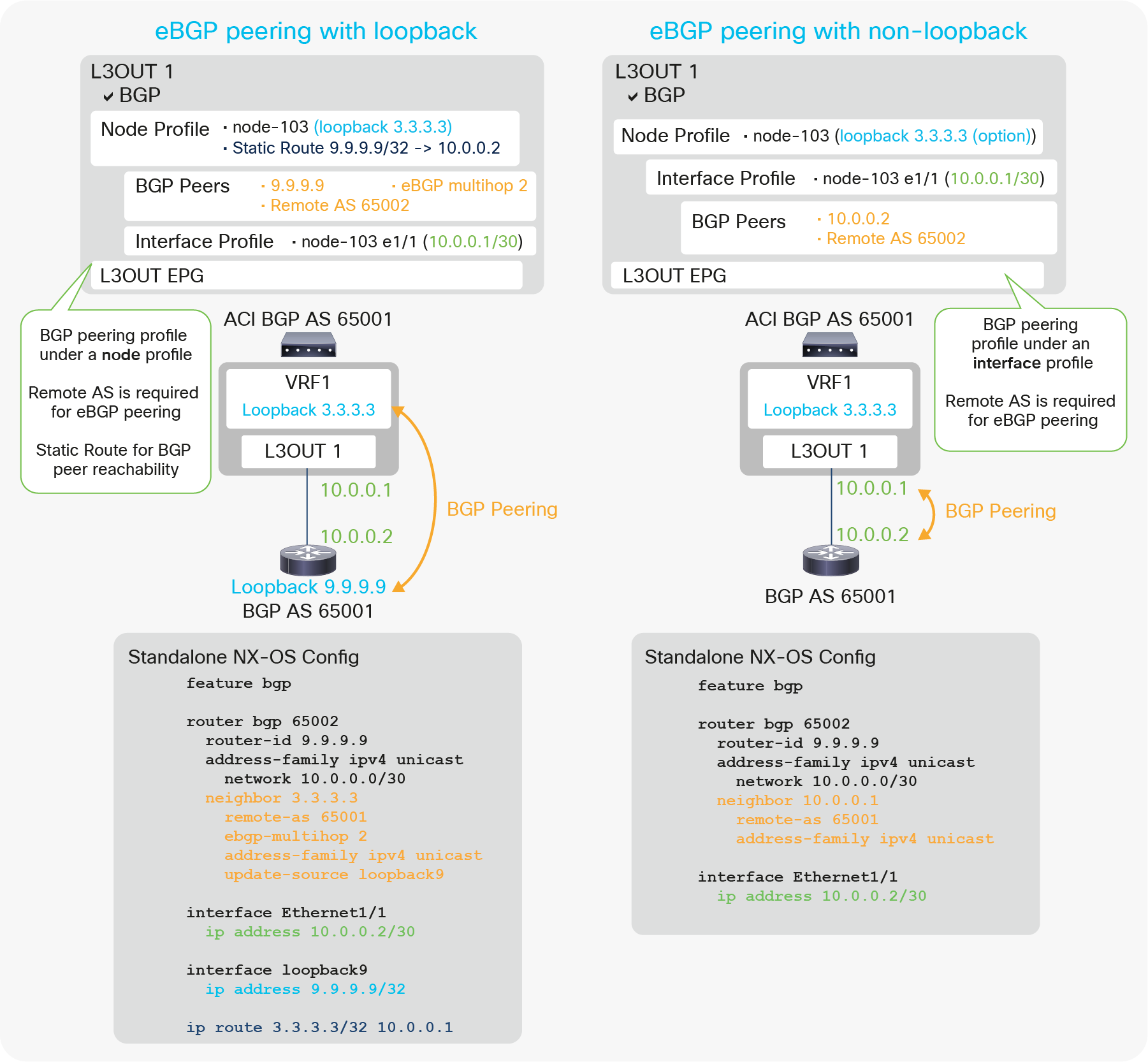
Figure 34 illustrates the configuration example for eBGP with peering on loopback and non-loopback interfaces. Most of the configurations are the same as the iBGP configuration in Figure 33. There are two more requirements specific to eBGP peering under the BGP Peer Connectivity Profile.
● Remote AS (not optional for eBGP)
● EBGP multihop (This is only when the peer is multiple-hops away, as in the case of loopback peering.)
| Note: The BGP Peer Connectivity Profiles contain many options. However, the minimum eBGP configuration just requires the neighbor IP address, Remote AS Number, and eBGP multihop. For details on other options, please see “BGP protocol options” in this section. |
Figure 35 and Figure 36 show the APIC GUI configuration for eBGP peering with a loopback, based on the configuration example in Figure 34 (eBGP peering with loopback). In case users need to use OSPF instead of a static route as the IGP, users can enable and configure OSPF in the same L3Out, or in another L3Out on the same border leaf. If OSPF and BGP are enabled in the same L3Out, OSPF is programmed only to advertise its L3Out loopback and interfaces. See the “L3Out OSPF” section for the OSPF configuration, since it is the same with or without BGP.
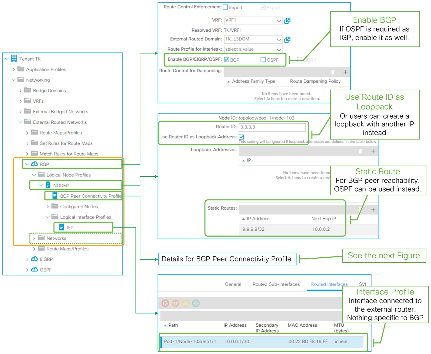
EBGP peering with loopback in GUI (APIC Release 3.2)
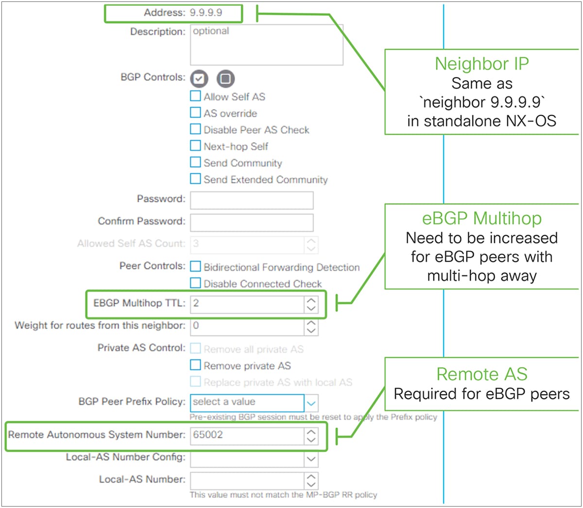
BGP Peer Connectivity Profile for eBGP peering in GUI (APIC Release 3.2)
● The BGP AS number for infra MP-BGP and route reflector is used for BGP L3Outs in the entire fabric.
● EBGP-peering support was added beginning with APIC Release 1.1(1).
● OSPF or static route is supported as IGP for BGP peer reachability. When OSPF is enabled in the BGP L3Out, OSPF is programmed only to advertise its L3Out loopback and interface subnets. Routes learned from OSPF are not distributed to other leaf switches via MP-BG.
● Sourcing BGP sessions via secondary IPs is not supported.
● L3Out BGP does not have an equivalent configuration for the “network <subnet>” command from standalone Cisco NX-OS. Instead, all configurations for subnet advertisement to outside are implemented via redistribution.
● By default, all routing protocols, static routes, and L3Out interface subnets are redistributed to BGP. This default redistribution is required for infra MP-BGP.
● Even though almost all types of routes are redistributed to the L3Out BGP, ACI does not advertise any of them to the outside, by default. To advertise a subnet, appropriate configurations are required such as BD subnet advertisement or Transit Routing. This is implemented by internally utilizing an outbound route-map for BGP peers.
● The outbound BGP peer route-map is per L3Out instead of per BGP peers. Hence, the subnet advertisement configuration in one L3Out will be applied to all BGP peers in the same L3Out. Please see the “BD subnet advertisement” section or the “Internal route-map for Transit Routing” section for details about internal route-map implementation. This was enhanced in APIC Release 4.2, which supports per-BGP peer route-map.
● There is an inbound BGP peer route-map per L3Out as well; this is for Import Route Control Enforcement. The same limitation as for outbound route-maps apply. This was enhanced in APIC Release 4.2, which supports per-BGP peer route-map.
● The outbound or inbound route-map for BGP peers can be checked using the following command:
| Leaf1# show bgp ipv4 unicast neighbors vrf TK:VRF1 | egrep 'BGP nei|Inb|Outb' BGP neighbor is 9.9.9.9, remote AS 65009, ebgp link, Peer index 1 Inbound route-map configured is imp-L3Out-BGP-peer-2916353, handle obtained Outbound route-map configured is exp-L3Out-BGP-peer-2916353, handle obtained The route-map name is in a form of “imp-L3Out-<L3Out name>-peer-<VRF VNID>” or “exp-L3Out-<L3Out name>-peer-<VRF VNID>”. |
BGP protocol options – neighbor level
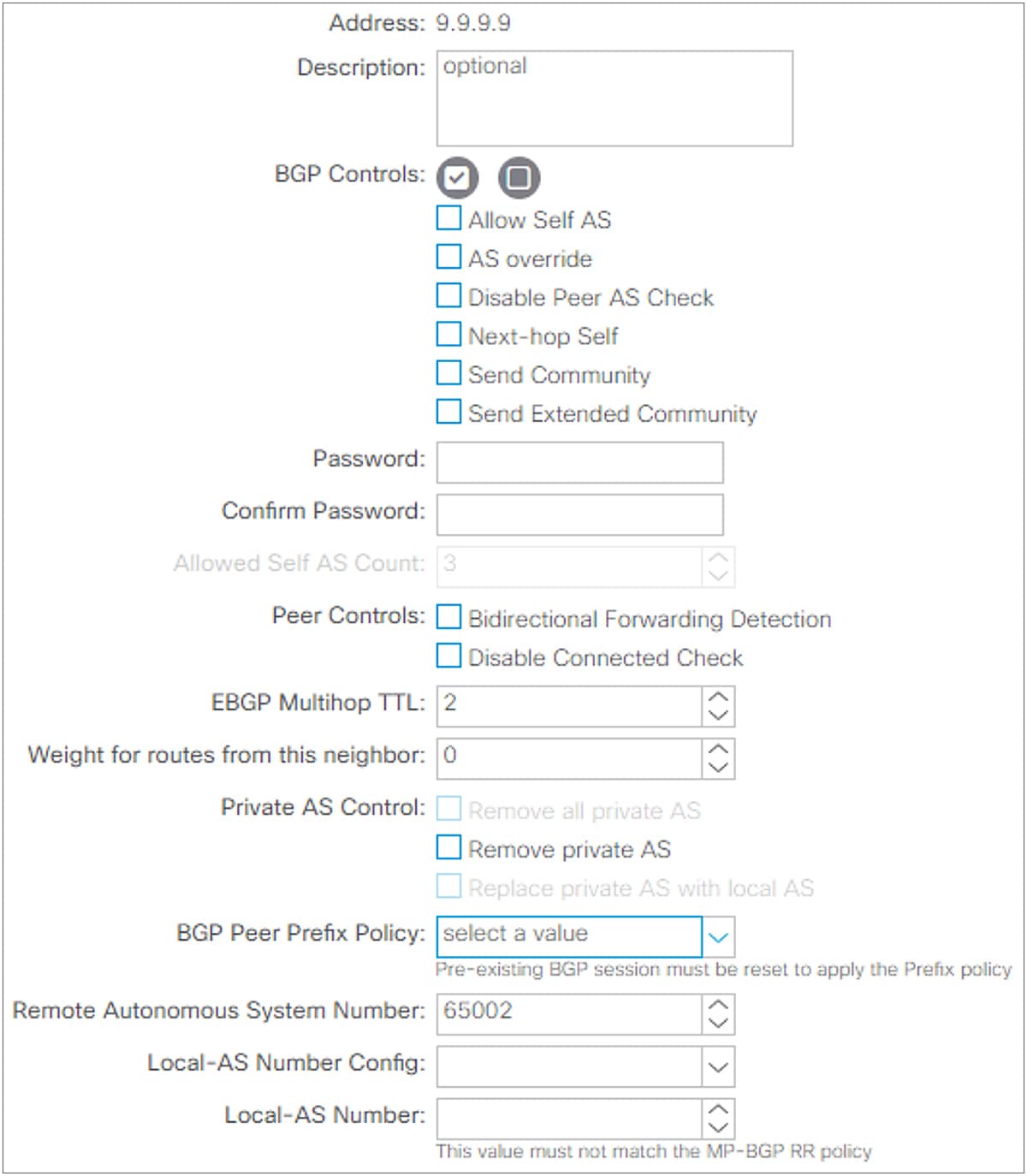
BGP Peer Connectivity Profile in GUI (APIC Release 3.2)
This subsection goes over all BGP protocol options per neighbor that can be configured on the BGP Peer Connectivity Profile under the Logical Node Profile or the Logical Interface Profile located under “Tenant > Networking > External Routed Networks > L3Out”. For various BGP set rules, see the “L3Out Route Profile / Route Map” section.
● Dynamic Neighbor (Prefix Peers)
This feature was introduced from APIC Release 1.2(2). This feature is to dynamically establish BGP peering with multiple neighbors by configuring a subnet (10.0.0.0/30 in Figure 38) instead of an individual IP address. This allows the L3Out to dynamically establish BGP peering with any IPs in the subnet. However, BGP with dynamic neighbor configuration does not start a BGP session by itself. Hence, the other side needs to explicitly configure the ACI border leaf IP to start a BGP session.
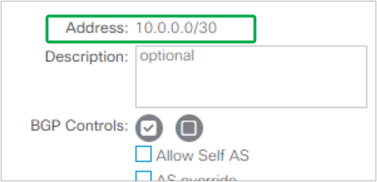
The standalone NX-OS equivalent command is the following:
| router bgp 65001 vrf TK:VRF1 neighbor 10.0.0.0/30 |
This feature is called Prefix Peers in standalone NX-OS.
● BGP Controls
Send Community and Send Extended Community have been supported from the first APIC release 1.0. The other options were introduced in later APIC releases.
◦ Allow Self AS
This feature was introduced in APIC Release 1.1(1) as a part of eBGP peering support. This option allows ACI to receive routes from the eBGP neighbor even if the routes have ACI BGP AS number in its AS_PATH. This option is valid only for eBGP peers.
The standalone NX-OS equivalent commands are the following:
| router bgp 65001 neighbor 9.9.9.9 address-family ipv4 unicast allowas-in <number> |
The <number> in the above equivalent command is the maximum count of Self AS occurrences in the AS_PATH. This <number> option is covered by Allowed Self AS Count option, described below.
◦ AS Override
This feature was introduced in APIC Release 3.1(2). It allows ACI to overwrite a remote AS in the AS_PATH with ACI BGP AS. In ACI, it is typically used when performing Transit Routing from eBGP L3Out to another eBGP L3Out with the same AS number. Otherwise, an eBGP peer device may not accept the route from ACI because of AS_PATH loop prevention. When this option is enabled, Disable Peer AS Check option also needs to be enabled. This option is valid only for eBGP peers.
The standalone NX-OS equivalent commands are the following:
| router bgp 65001 neighbor 9.9.9.9 address-family ipv4 unicast as-override |
◦ Disable Peer AS Check
This feature was introduced in APIC Release 1.1(1) as a part of eBGP peering support. It allows ACI to advertise a route to the eBGP peer even if the most recent AS in the AS_PATH of the route is the same as the remote AS for the eBGP peer. Without this option, ACI does not advertise such routes, just as a standalone NX-OS does not. If the remote AS in the AS_PATH is not the most recent one, the route advertisement is not affected by this option, and the route is advertised without any additional configurations. This option is valid only for eBGP peers.
The standalone NX-OS equivalent commands are the following:
| router bgp 65001 neighbor 9.9.9.9 address-family ipv4 unicast disable-peer-as-check |
◦ Next-hop Self
This feature allows ACI to update the next-hop when advertising a route from eBGP peer to iBGP peer. By default, route advertisement between iBGP peers keep the original next-hop of the route while the one between eBGP peers always updates the next-hop with a self IP.
The standalone NX-OS equivalent commands are the following:
| router bgp 65001 neighbor 9.9.9.9 address-family ipv4 unicast next-hop-self |
◦ Send Community
This feature has been supported from the first APIC release 1.0. This option needs to be enabled for ACI L3Out to advertise routes with a BGP Community attribute, such as AS2:NN format. Otherwise, the BGP Community attribute is stripped when routes are advertised to the outside. See the “L3Out Route Profile / Route Map” section for details about how to set or match communities on L3Out.
The standalone NX-OS equivalent commands are the following:
| router bgp 65001 neighbor 9.9.9.9 address-family ipv4 unicast send-community {standard} |
◦ Send Extended Community
This feature has been supported from the first APIC release 1.0. This option needs to be enabled for ACI L3Out to advertise routes along with the BGP Extended Community attribute, such as RT:AS2:NN, RT:AS4:NN, etc. Otherwise, the BGP Extended Community attribute is stripped when routes are advertised to the outside. See the “L3Out Route Profile / Route Map” section for details about how to set or match extended communities on L3Out.
The standalone NX-OS equivalent commands are the following:
| router bgp 65001 neighbor 9.9.9.9 address-family ipv4 unicast send-community extended |
● Password / Confirm Password
This feature has been supported from the first APIC release 1.0. When configured, L3Out BGP uses MD5 authentication on BGP TCP session. Password configuration can be reset via “Reset Password” by right clicking the BGP Peer Connectivity Profile or via the edit/action dropdown as shown in Figure 39.
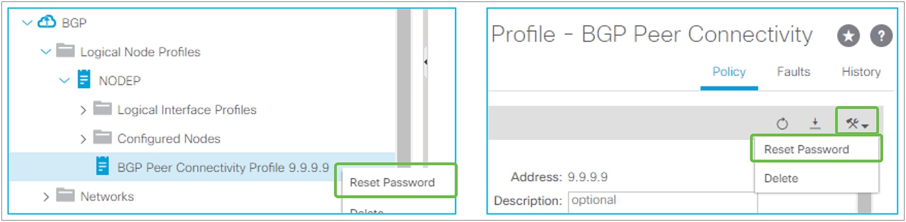
BGP Peer Connectivity Profile (Reset Password)
The standalone NX-OS equivalent commands are the following:
| router bgp 65001 neighbor 9.9.9.9 password <your password> |
● Allowed Self AS Count
This feature was introduced from APIC Release 1.1(1) as a part of eBGP peering support. This feature is to set the maximum count for the Allow Self AS option under BGP controls. See above for details on the Allow Self AS option.
● Peer Controls
◦ Bidirectional Forwarding Detection (BFD)
This feature was introduced in APIC Release 1.2(2). It is used to enable BFD on the BGP neighbor. See the “L3Out BFD” section for details.
The standalone NX-OS equivalent commands are the following:
| router bgp 65001 vrf TK:VRF1 neighbor 9.9.9.9 bfd |
◦ Disable Connected Check
This feature was introduced in APIC Release 1.1(1) as a part of eBGP peering support. For eBGP peering, BGP process checks whether the neighbor IP is on the same subnet as any of its local interfaces to see if the neighbor IP is directly connected. If not, it automatically assumes the TTL needs to be larger than 1. Hence, when BGP is peering via loopbacks with directly connected routers, the BGP peering will be rejected without the eBGP multihop TTL being set to 2 or larger, even though TTL 1 is technically enough. Disable Connected Check can be used in such a scenario as an alternative to increasing the eBGP multihop TTL in cases where there is a security concern in increasing TTL unnecessarily.
The standalone NX-OS equivalent commands are the following:
| router bgp 65001 neighbor 9.9.9.9 disable-connected-check |
● EBGP Multihop TTL
This feature was introduced in APIC release 1.1(1) as a part of eBGP peering support. For eBGP peering, BGP control packets use a TTL of 1 by default. This needs to be increased via this option in case the neighbor IP is multihops away. If the required TTL is 1, but the neighbor IP is not in directly connected subnets (for example, the neighbor IP is a loopback IP on a directly connected router), Disable Connected Check under Peer Controls can be used instead.
The standalone NX-OS equivalent commands are the following:
| router bgp 65001 neighbor 9.9.9.9 ebgp-multihop <number> |
● Weight
This feature was introduced in APIC Release 1.2(2). This sets a default value of Cisco proprietary BGP path attribute Weight on all the routes advertised to this neighbor.
The standalone NX-OS equivalent commands are the following:
| router bgp 65001 neighbor 9.9.9.9 address-family ipv4 unicast weight <number> |
● Private AS Control
This feature was introduced in APIC Release 1.2(2). These options are valid only when ACI BGP AS is a public AS number.
◦ Remove private AS
In outgoing eBGP route updates to this neighbor, remove all private AS numbers from the AS_PATH when the AS_PATH has only private AS numbers.
If the neighbor remote AS is in the AS_PATH, this option is not applied.
◦ Remove all private AS
In outgoing eBGP route updates to this neighbor, remove all private AS numbers from the AS_PATH regardless of whether a public AS number is included in the AS_PATH.
If the neighbor remote AS is in the AS_PATH, this option is not applied.
To enable this option, Remove private AS needs to be enabled.
◦ Replace private AS with local AS
In outgoing eBGP route updates to this neighbor, replace all private AS numbers in the AS_PATH with ACI local AS regardless of whether a public AS or the neighbor remote AS is included in the AS_PATH.
To enable this option, Remove all private AS needs to be enabled.
The standalone NX-OS equivalent commands are the following:
| router bgp 65001 neighbor 9.9.9.9 address-family ipv4 unicast remove-private-as remove-private-as all remove-private-as replace-as |
● BGP Peer Prefix Policy (maximum prefix)
This feature was introduced in APIC Release 1.2(1). This option is to set an action to take when the number of received prefixes from this neighbor exceeds the configured maximum number. Note that the number of received prefixes is calculated by the number of prefixes and their next hops. If one prefix has two next hops, it is counted as two entries. This option is activated by attaching the BGP Peer Prefix Policy (Figure 40) to the BGP Peer Connectivity Profile.
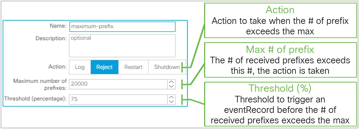
BGP Peer Prefix Policy in GUI (APIC Release 3.2)
◦ Action
These are the actions that will be taken when the number of received prefixes from this neighbor exceeded the configured value.
● Log: A fault F1215 is raised to warn users that the number of received prefixes has exceeded the maximum. If the maximum number of prefixes is set to 10, the fault is raised when 11 prefixes are learned.
● Reject: A fault F1215 is raised to warn users that the number of received prefixes has exceeded the maximum. No more prefixes are learned from this neighbor until the number of received prefixes is reduced. If the maximum number of prefixes is set to 10, the fault is raised when 11 prefixes are learned and the 12th prefix is rejected.
● Restart: The BGP peer is shut down due to the maximum prefix violation, and a fault F1214 is raised. The BGP peer will be re-established after the configured interval if the number of received prefixes drops below the maximum number. When this action is selected, “Restart Time (min)” configuration becomes available. If the maximum number of prefixes is set to 10, the BGP peer is shut down when 11 prefixes are learned.
● Shutdown: The BGP peer is shut down due to the maximum prefix violation, and a fault F1214 is raised. If the maximum number of prefixes is set to 10, the BGP peer is shut down when 11 prefixes are learned.
◦ Maximum number of prefixes
When the number of received prefixes exceeds this number, the configured action is taken. The default value is 20,000 prefixes.
◦ Threshold (percentage)
When the number of received prefixes exceeds the threshold, a warning (eventRecord) is raised as a precautionary warning. If the maximum number of prefixes is 10 and the threshold is 70 percent, a warning is raised when 8 prefixes are learned. The default value is 75 percent.
The standalone NX-OS equivalent commands are the following:
| router bgp 65001 vrf TK:VRF1 neighbor 9.9.9.9 address-family ipv4 unicast maximum-prefix <prefix number> <threshold %> maximum-prefix <prefix number> <threshold %> restart <min> maximum-prefix <prefix number> <threshold %> warning-only |
● Remote AS
This feature was introduced in APIC release 1.1(1) as a part of eBGP peering support. This is required for eBGP peering to specify the AS number of the neighbor. When it is blank, it automatically uses the ACI BGP AS number. Hence, this field is optional for iBGP peering.
The standalone NX-OS equivalent commands are the following:
| router bgp 65001 vrf TK:VRF1 neighbor 9.9.9.9 remote-as <AS #> |
● Local AS / Local AS Config
This feature was introduced in APIC Release 1.1(1) as a part of eBGP peering support. This feature is used when L3Out needs to disguise its own BGP AS with the configured local AS to peer with this neighbor. When this feature is used, for this neighbor it will look like there is one more AS (local AS) between itself and the ACI BGP AS. Hence, the neighbor will peer with the configured local AS instead of the real ACI BGP AS. In such situations, both the local AS and the real ACI BGP AS are added to the AS_PATH of routes advertised to the neighbor. The local AS is also prepended to routes learned from the neighbor.
The following additional options are available, as in a standalone NX-OS:
◦ no-prepend
This option prevents ACI from prepending the local AS in the AS_PATH of routes learned from this neighbor.
◦ no-prepend, replace-as
This option allows ACI to add only a local AS, instead of both a local AS and a real ACI BGP AS, to AS_PATH of routes advertised to this neighbor on top of the no-prepend option effect.
◦ no-prepend, replace-as, dual-as
This option allows the neighbor to peer with both a local AS and a real ACI BGP AS on top of the no-prepend and replace-as option effect. However, note that the neighbor receives route updates with AS_PATH with AS that it is peering with, regardless of whether it is a local AS or a real ACI BGP AS.
The standalone NX-OS equivalent commands are the following:
| router bgp 65001 vrf TK:VRF1 neighbor 9.9.9.9 local-as <AS #> local-as <AS #> no-prepend local-as <AS #> no-prepend replace-as local-as <AS #> no-prepend replace-as dual-as |
BGP protocol options – L3Out/node level
● BGP Protocol Profile
This is a profile to apply a BGP Timer Policy and BGP Best Path Control Policy per node via the Logical Node Interface Profile.
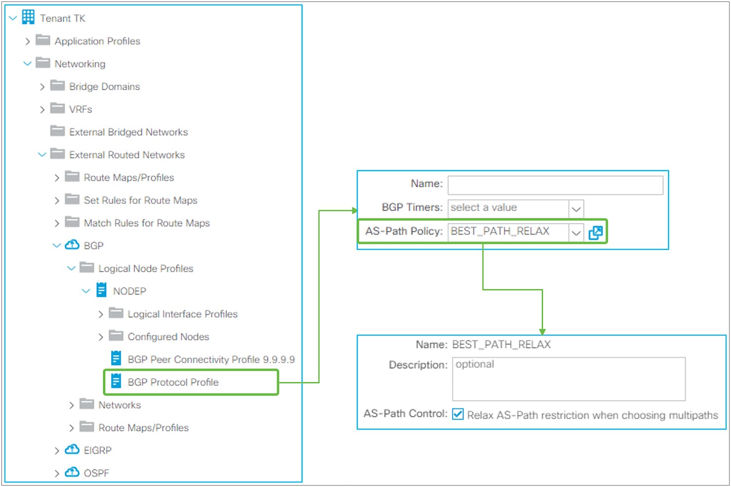
BGP Protocol Profile in GUI (APIC Release 3.2)
◦ BGP Timers
This can be applied per VRF as well as per node. The details are in the “BGP protocol options – VRF level” subsection, below.
◦ AS-Path Policy
This is to apply AS-Path Policy (BGP Best Path Control Policy) per node. This option was introduced in APIC Release 3.2(7). APIC Release 4.0, 4.1, and 4.2(1) do not support this option. When “AS-Path Control” is enabled, it allows ECMP across different eBGP peers (that is, different AS paths).
The standalone NX-OS equivalent commands are the following:
| router bgp 65001 vrf TK:VRF1 bestpath as-path multipath-relax |
◦ BGP Route Dampening
This feature was introduced in APIC Release 1.2(2). This is used to stop advertising flapping routes. When a BGP route status changes from available to unavailable or vice versa, a penalty of 1000 is added to the route. When the penalty exceeds the Suppress Limit, the route is marked as dampened, and a router stops advertising the route. The penalty of each route will be reduced by half once the Half Life time has passed. Once the penalty goes below half of the Reuse Limit, the penalty is completely removed from the route.
In ACI, these route-dampening parameters are configured via Set Policy in Route Profile without any Match Policy. The Route Profile for BGP Route Dampening is on the tenant level instead of each individual L3Out level. Please see the “L3Out Route Profile / Route Map” section for details on Route Profile itself.
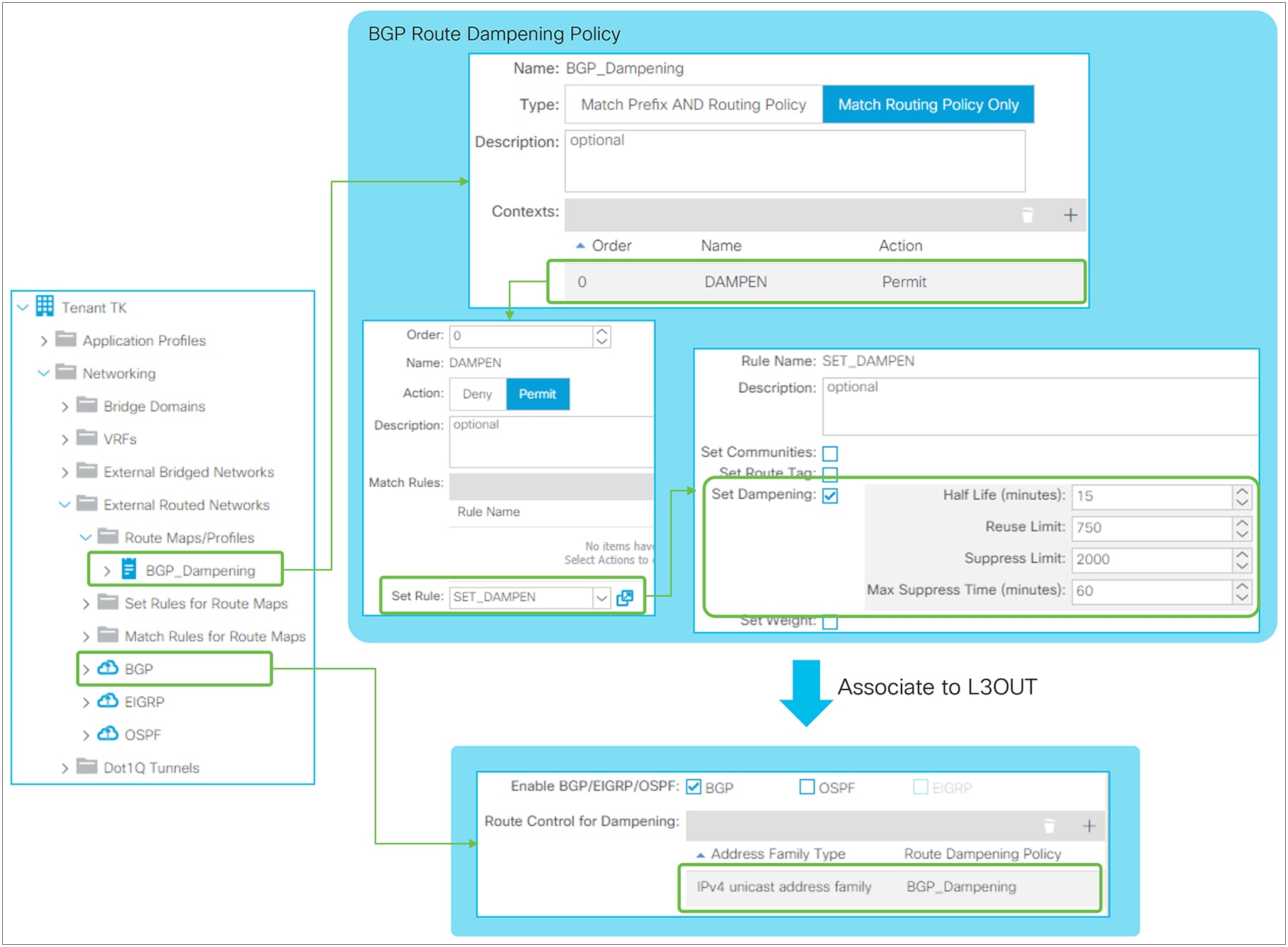
BGP Route Dampening Policy in GUI (APIC Release 3.2)
◦ Half Life (minutes)
The penalty of each route will be reduced by half when the Half Life time has passed.
◦ Reuse Limit
Routes will be used and advertised again once the penalty of routes go below the Reuse Limit.
◦ Suppress Limit
Routes will be suppressed and not be advertised once the penalty of routes exceeds the Suppress Limit.
◦ Max Suppress Time (minutes)
Routes will be unsuppressed and advertised again after Max Suppress Time, regardless of penalty. This is to ensure the prefix does not get dampened indefinitely.
The standalone NX-OS equivalent commands are the following:
| route-map BGP_dampening set dampening <Half Life> <Reuse Limit> <Suppress Limit> <Max Suppress> router bgp 65001 vrf TK:VRF1 address-family ipv4 unicast dampening route-map BGP_dampening |
BGP protocol options – VRF level
● BGP timer policy
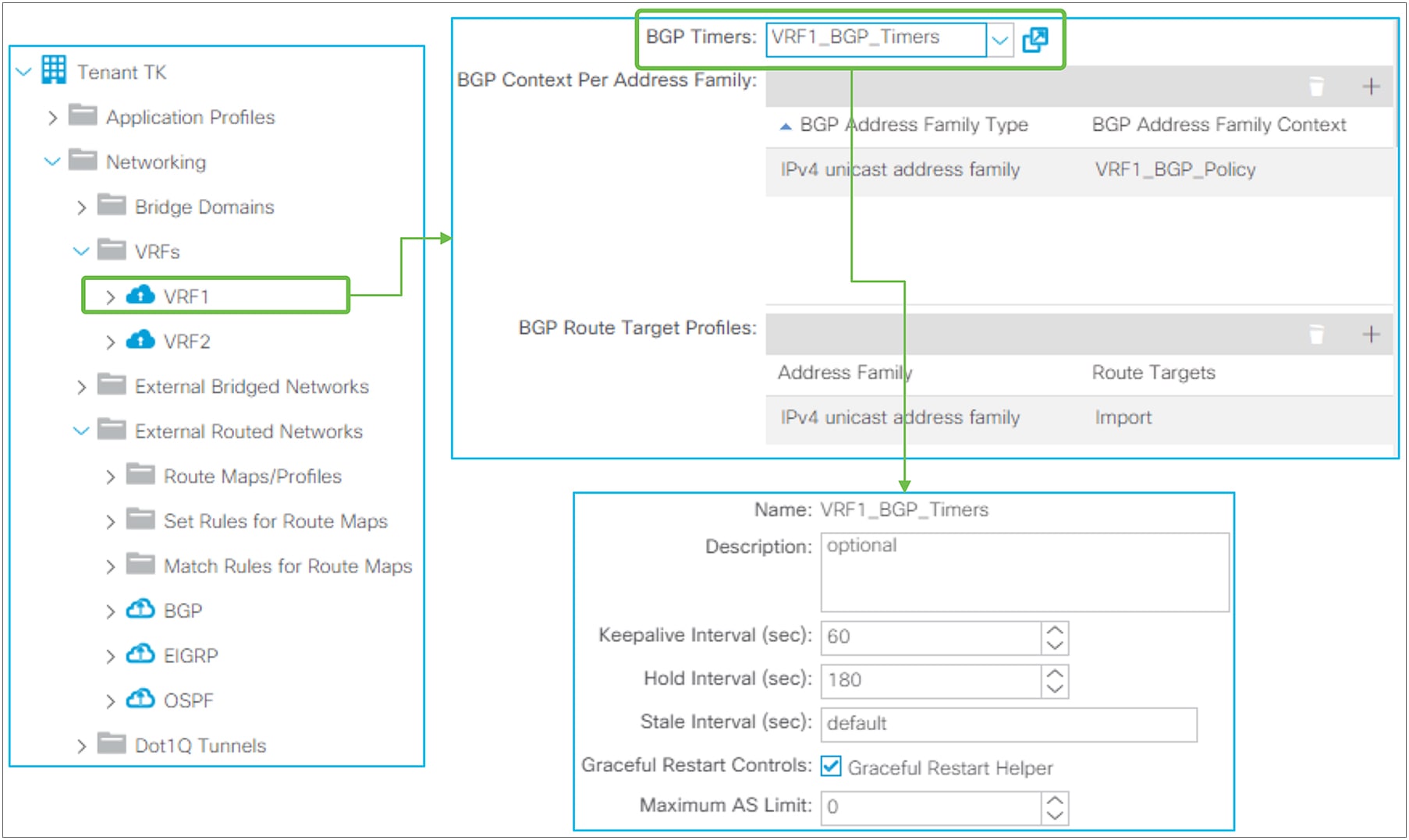
BGP timer policy in GUI (APIC Release 3.2)
BGP timer policy itself is located under “Tenant > Policies > BGP > BGP Timers”. It is associated to a VRF under “Tenant > Networking > VRFs”. Beginning in APIC Release 2.2(2), BGP Timer Policy can be configured via right-clicking on the Logical Node Profile to make the scope of BGP Timer Policy per Node per VRF instead of per VRF.
◦ Keepalive Interval (sec) / Hold Interval (sec)
Once a BGP peer is established, keepalive messages are sent to the neighbor once in every Keepalive Interval. If no keepalive message was received within a Hold Interval, the BGP peer is considered down. The default value is 60 seconds for a Keepalive Interval and 180 seconds for a Hold Interval (= 3 x Keepalive Interval). Configured intervals take effect only after a new BGP session is established because the Hold Interval is exchanged via a BGP OPEN message and negotiated to the lower value. If the locally configured Keepalive Interval is larger than one-third (33 percent) of the negotiated Hold Interval, one-third of the negotiated Hold Interval is used as a Keepalive Interval instead of the configured value.
The standalone NX-OS equivalent commands are the following:
| router bgp 65001 vrf TK:VRF1 timers bgp <keepalive interval> <hold interval> |
◦ Stale Interval (sec)
When a Graceful Restart is in progress, the routes previously received from the peer are still used for forwarding but marked as stale. Once the session between two routers is re-established and route information is synced again, all the stale routes are deleted and the latest routes from the latest exchange are used. The Stale Interval is a timer to delete those stale routes in case the session is not re-established within this interval. This interval is applied locally. The default value is 300 seconds.
The standalone NX-OS equivalent commands are the following:
| router bgp 65001 vrf TK:VRF1 graceful-restart stalepath-time <stale interval> |
◦ Graceful Restart Controls
When Graceful Restart is in progress, one router may be restarting its routing process and triggering Graceful Restart. Also, its peer may be stable but simply helping the Graceful Restart operation with the restarting router. The latter is called a Graceful Restart Receiving device or Graceful Restart Helper. Cisco ACI provides only Graceful Restart Helper capability because ACI does not support stateful supervisor switchover within each individual switch node. Only a cold reboot is available. Instead, routing protocol High Availability (HA) is achieved via utilizing multiple switch nodes. Because of this,
◦ Graceful Restart Helper
Enables Graceful Restart Helper Capability within the VRF. The default is enabled.
The standalone NX-OS equivalent commands are the following:
| router bgp 65001 vrf TK:VRF1 no graceful-restart graceful-restart-helper |
In Graceful Restart, there are two major timers. One is called restart timer, which is configured and advertised by a restarting router to inform its peer of the maximum time it will take for the restarting router to finish restarting its routing protocol. A Graceful Restart Helper device will delete all stale routes once this timer is expired by assuming the restarting device failed to restart its routing protocol. Hence, this timer is not configured on ACI (Graceful Restart Helper). Another timer, called a stale timer, is configured and used by the Graceful Restart Helper device. Please see the Stale Interval option, above.
◦ Maximum AS Limit
This feature was introduced in APIC Release 2.0(1). It discards eBGP routes that have a number of AS-path segments that exceed the specified limit. The default value is zero, which implies no maximum as limit.
The standalone NX-OS equivalent commands are the following:
| router bgp 65001 vrf TK:VRF1 maxas-limit <number> |
● Address Family Context
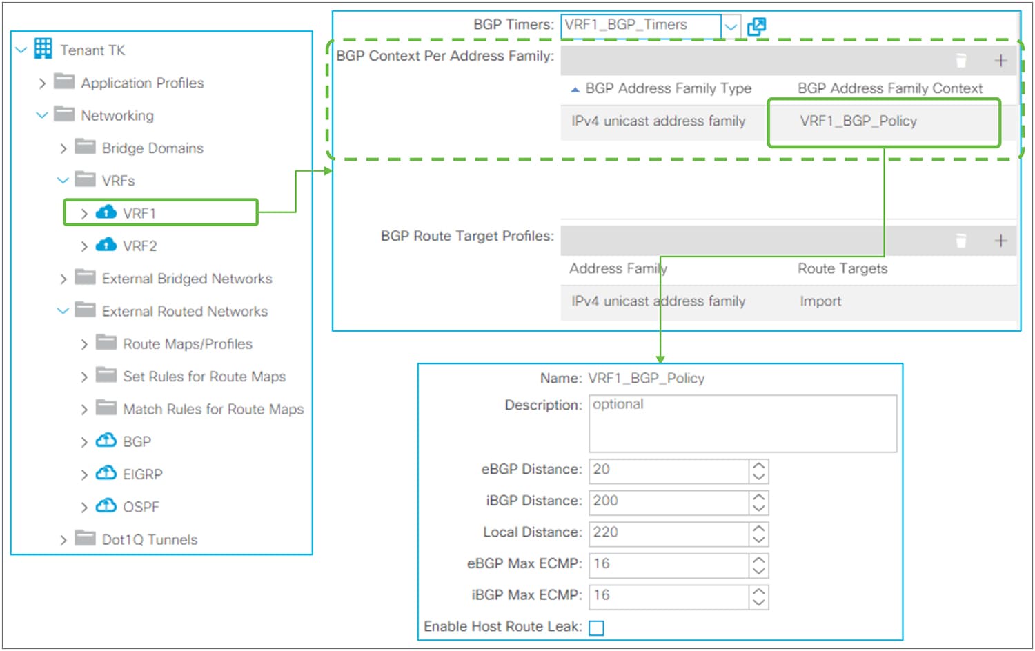
BGP Address Family Context Policy in GUI (APIC Release 3.2)
BGP Address Family Context Policy itself is located under “Tenant > Policies > BGP > BGP Address Family Context”. It is associated to a VRF under “Tenant > Networking > VRFs”.
◦ eBGP / iBGP / Local Distance
This feature was introduced in APIC Release 1.2(1). Administrative Distance (AD) for BGP. The default values are as follows:
◦ eBGP: 20
◦ iBGP: 200
◦ Local: 220 (Local AD is used for aggregate discard routes when they are installed in the RIB.)
The standalone NX-OS equivalent commands are the following:
| router bgp 65001 vrf TK:VRF1 address-family ipv4 unicast distance <eBGP AD> <iBGP AD> <Local AD> |
◦ eBGP / iBGP Max ECMP
This feature was introduced in APIC Release 3.0(1). It configures the maximum number of paths that BGP adds to the route table for ECMP.
The standalone NX-OS equivalent commands are the following:
| router bgp 65001 vrf TK:VRF1 address-family ipv4 unicast maximum-paths <eBGP ECMP number> maximum-paths ibgp <iBGP ECMP number> |
◦ Enable Host Route Leak
This feature was introduced in APIC Release 2.1(1). This is for the GOLF feature. This is enabled when users need to advertise eVPN Type-2 (host MAC/IP) routes via GOLF on top of eVPN type-5 routes (BD subnets). Please check the “GOLF” section in the Cisco APIC Layer 3 Networking Configuration Guide.
This feature was introduced in APIC Release 1.2(2). This feature is to advertise only a summarized prefix for BD subnets or Transit Routes from the ACI BGP L3Out to outside. The behavior is equivalent to “aggregate-address <prefix> summary-only” in NX-OS commands.
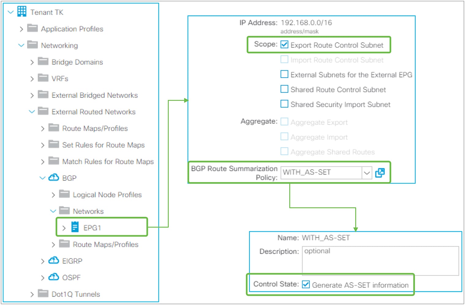
BGP Route Summarization in GUI (APIC Release 3.2)
BGP Routing Summarization in ACI is configured by adding a route summarization policy to an L3Out subnet with scope “Export Route Control Subnet,” because it is used to advertise (export) routes from ACI to outside. Please refer to the “L3Out Transit Routing” section for details about the “Export Route Control Subnet” scope.
By adding a route-summarization policy to the L3Out subnet, as shown in Figure 45, the border leaf will try to create a Null-0 entry for the summarized route (192.168.0.0/16 in Figure 45), which will be advertised to its BGP peers. Please be aware that, just like a normal BGP router, the summarization will not occur if no contributing routes exist in the IPv4/IPv6 BGP table for the user VRF on the border leaf.
A supported configurable option is the following:
● Generate AS-SET information
When enabled, the summarized route will have an AS-PATH attribute and community information from the contributing routes.
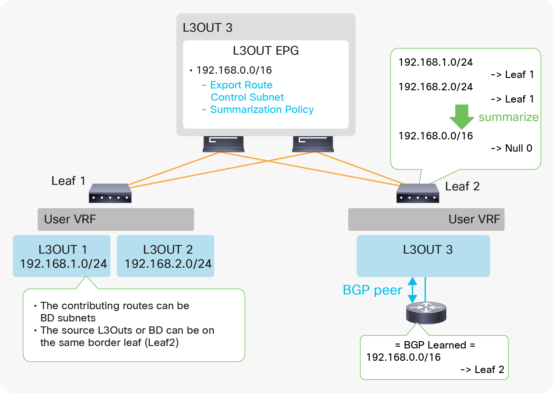
Example of BGP Route Summarization topology
Figure 46 depicts when L3Out 3 advertises only a summarized transit subnet information (192.168.0.0/16) instead of each subnet (192.168.1.0/24 and 192.168.2.0/24). The summarized route with Null-0 next-hop is advertised only to the outside and is not advertised to other leaf switches via infra MP-BGP. In case BGP is summarizing BD subnets, a correct BD subnet advertisement configuration is required for at least one contributing BD subnet on top of the summarization configuration (see the “ACI BD subnet advertisement” section).
The standalone NX-OS equivalent commands are the following:
| router bgp 65001 vrf TK:VRF1 address-family ipv4 unicast aggregate-address <prefix> summary-only {as-set} |
BGP default route advertisement
There are two methods to advertise a default route (0.0.0.0/0) from BGP L3Out to the outside.
1. Transit Routing
2. Default Route Leak Policy
Transit Routing will advertise a default route that is learned from another L3Out or possibly a static route configured on another L3Out. See the “L3Out Transit Routing” section for details on Transit Routing.
Default Route Leak Policy is equivalent to “default-originate” in standalone NX-OS.
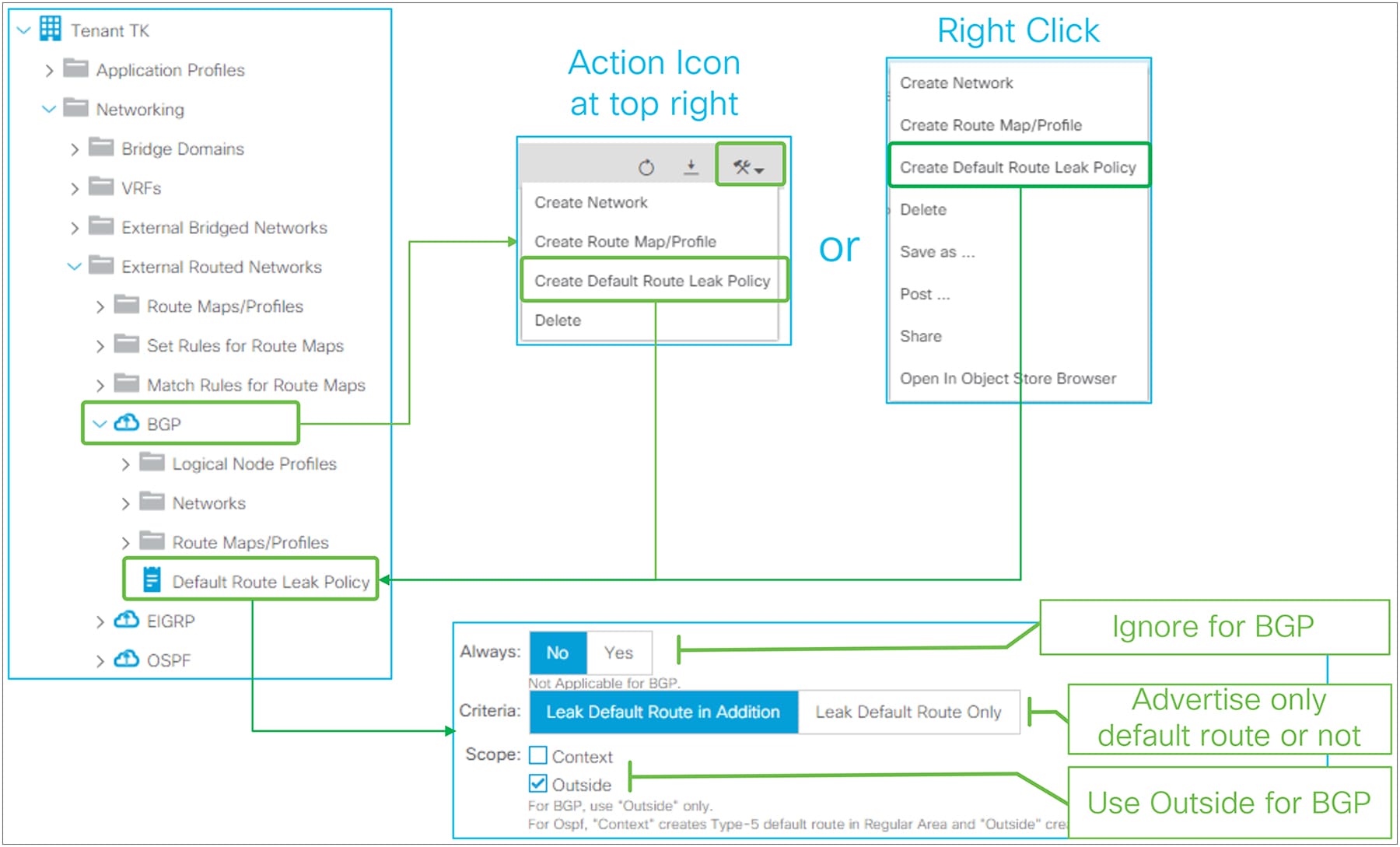
Default Route Leak Policy for BGP in GUI (APIC Release 3.2)
Default Route Leak Policy was introduced in APIC Release 1.1(1) and can be created under an L3Out through either of the following means:
● “Create Default Route Leak Policy” from a dropdown menu at the top right in L3Out
● “Create Default Route Leak Policy” from the right-click menu in L3Out itself
Default Route Leak Policy has the following parameters:
● Always
Ignore this option for BGP.
● Criteria
Use “Leak Default Route in Addition” when a default route needs to be advertised on top of other routes. Use “Leak Default Route Only” when only a default route should be advertised.
When “Leak Default Route Only” is selected, deny-all is applied to outbound route-maps on each BGP peer in this L3Out.
● Scope
Use “Outside” for BGP.
The standalone NX-OS equivalent commands are the following:
| router bgp 65001 vrf TK:VRF1 neighbor 9.9.9.9 address-family ipv4 unicast default-originate |
Basic OSPF configuration is much simpler than BGP in ACI because there is no need to take ACI BGP AS from infra MP-BGP into consideration.
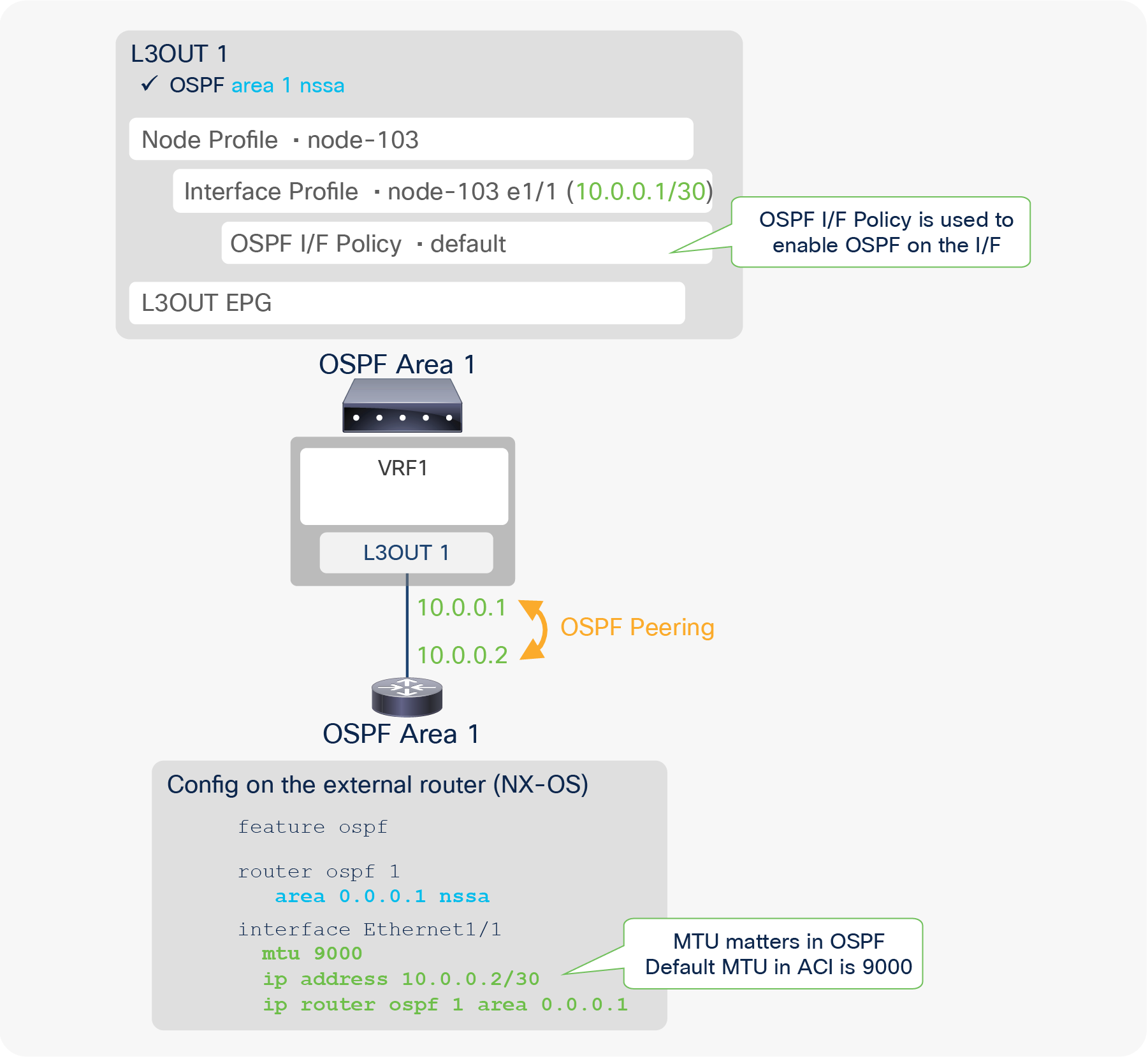
Figure 48 illustrates a configuration example for OSPF with area 1, which is NSSA (Not-So-Stubby-Area) for ACI and the external router (in this case, NX-OS). The two required components specifically for OSPF are the following:
● Area and its Area Type
This implies one L3Out means one OSPF area. If multiple OSPF areas need to be configured, as shown in Figure 50, multiple L3Outs also need to be configured.
● Enable OSPF on the interface
This is performed via creating OSPF I/F Policy under the Logical Interface Profile. This is equivalent to performing the standalone NX-OS command “ip router ospf default area x” on the interfaces configured in the Logical Interface Profile. In the OSPF I/F Policy, although users can configure authentication, interface network type, etc., typically all the values can be left as defaults, just as in a standalone NX-OS.
Other key points to successfully establish an OSPF neighbor on ACI is to ensure all the OSPF neighbor criteria match with their neighbors, such as MTU, network mask, area ID, area type, etc.
Figure 49 shows an example of an APIC GUI configuration.
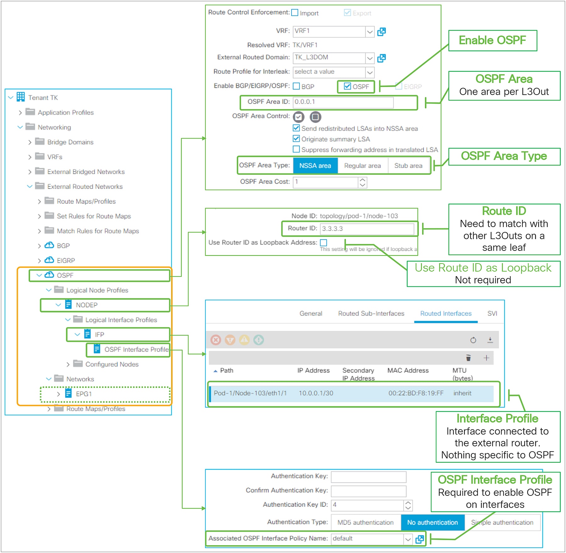
Basic configuration of OSPF in GUI (APIC Release 3.2)
● Each OSPF L3Out represents one OSPF area.
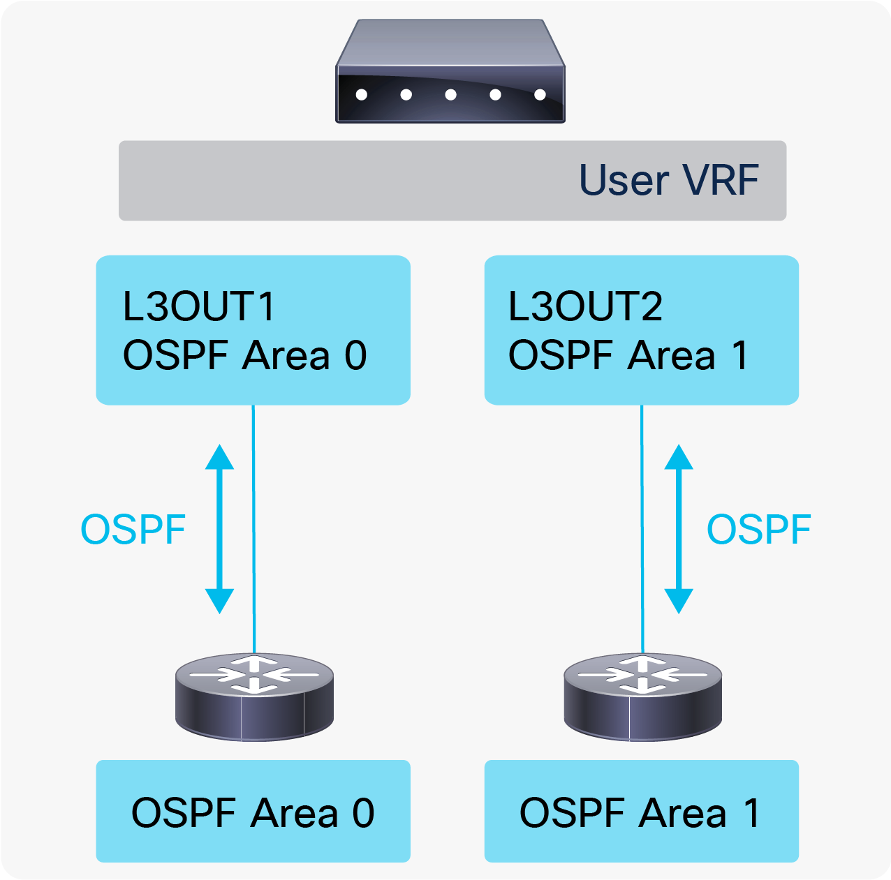
◦ When two OSPF L3Outs are on the same leaf, those need to be in a different OSPF area.
◦ When two OSPF L3Outs are on different leaf switches, those can be in the same OSPF area.
● When OSPF is enabled in the same L3Out as BGP, OSPF is programmed only to advertise its L3Out loopback and interface subnets. In such a case, other L3Outs cannot use OSPF on the same border leaf in the same VRF (a fault F0467 will be raised).
In case OSPF needs to advertise a BD subnet or perform Transit Routing on top of helping BGP peer reachability, OSPF needs to be enabled via another L3Out, but on the same interface as the BGP L3Out with the same parameters such as IP address (also use “Encap Scope VRF” in case of SVI).
● When multiple external routers are connected to an OSPF L3Out with the same SVI/VLAN, which means in the same L3Out BD, the external routers will form a neighbor directly to each other. See Figure 20 in the “L3Out bridge domain” section for details.
In such a scenario, external routers will exchange routes directly by sending OSPF LSAs through the ACI L3Out BD. Hence, a situation similar to Transit Routing with “Export Route Control Subnet” may occur without “Export Route Control Subnet”.
● When advertising a BD subnet or performing Transit Routing, routes are redistributed into OSPF LSDB (Link-State Database) via a route map that is automatically created on a border leaf. This route map is shared with EIGRP and other OSPF L3Outs on the same leaf in the same VRF. It implies that subnet advertisement configuration on one L3Out may affect other L3Outs. Hence, awareness of this implementation is required when there are other L3Outs on the same leaf in the same VRF. See Figure 93 in the “L3Out Transit Routing” section for details.
● IPv6 (OSPFv3) has been supported since APIC Release 1.1(1).
OSPF protocol options – interface level
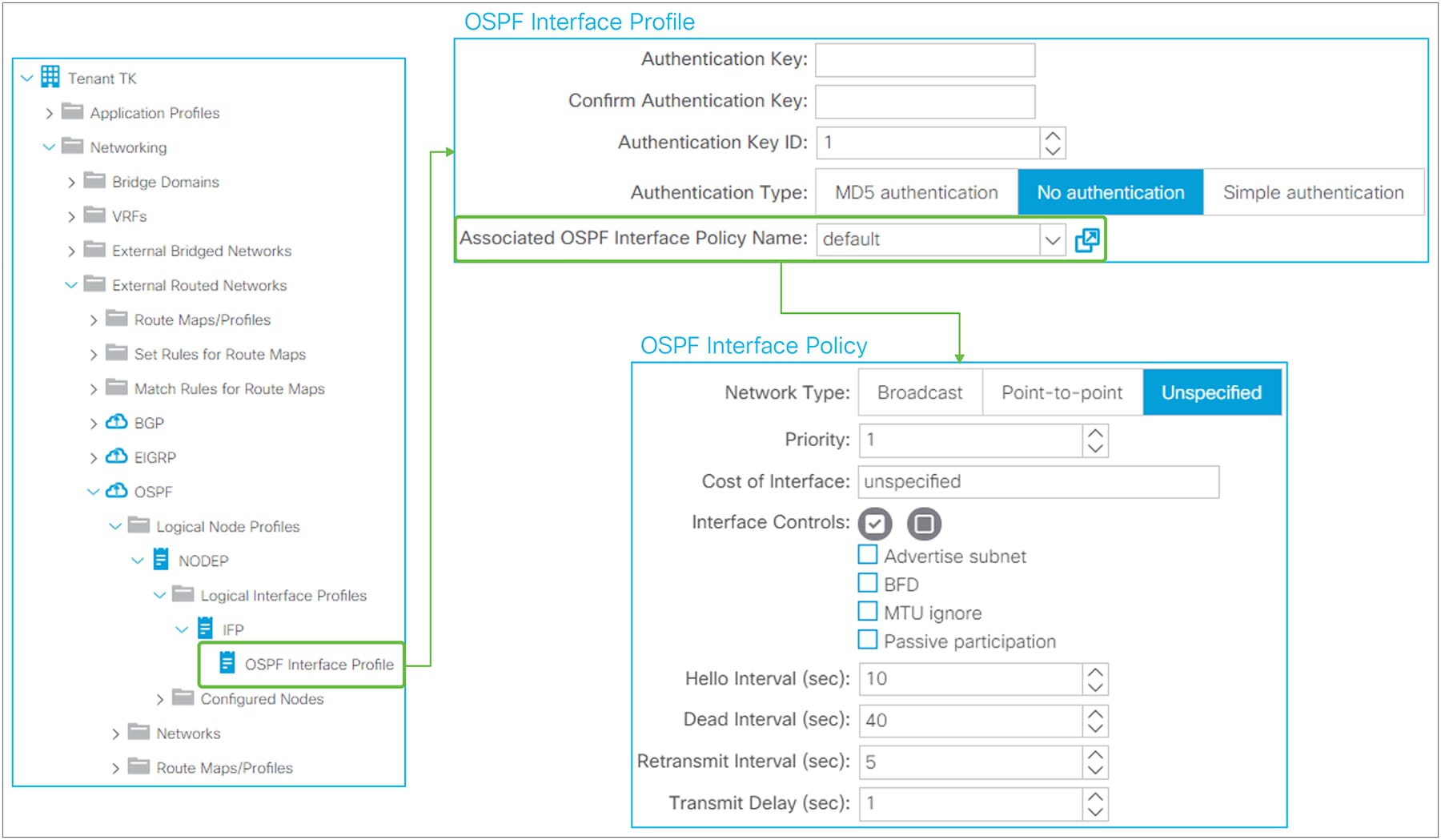
OSPF Interface Profile and Policy in GUI (APIC Release 3.2)
The interface-level OSPF configuration from the OSPF Interface Profile is applied to all interfaces in the associated Logical Interface Profile. The OSPF Interface Policy itself is located under “Tenant > Policies > OSPF > OSPF Interface”.
● Authentication
This is the OSPF authentication on each interface level.
◦ Authentication Key: This is a password used for both Simple and MD5 authentication.
◦ Authentication Key ID: This is a key ID for MD5 authentication. This needs to match with neighbor devices.
◦ Authentication Type: No authentication, Simple, or MD5.
The standalone NX-OS equivalent commands are the following:
| interface eth1/1 ip ospf authentication ip ospf authentication-key <password>
interface eth1/1 ip ospf authentication message-digest ip ospf message-digest-key <key id> md5 <password> |
● Network Type
◦ Broadcast
A network with multiple routers that can communicate over a shared medium that allows broadcast traffic, such as Ethernet. Typically used for interface type SVI. OSPF DR (designate router) / BDR (backup designated router) election occurs with this type.
◦ Point-to-point
A network that exists only between two routers. Typically used for interface type routed interface or subinterface. OSPF DR / BDR election does not occur with this type.
◦ Unspecified
The Network Type is unspecified and takes a default value, which is broadcast.
The standalone NX-OS equivalent commands are the following:
| interface eth1/1 ip ospf network <broadcast or point-to-point> |
● Priority
This is a priority for OSPF DR / BDR election. A router with a higher number is selected as the DR or BDR. When the priority of the neighbors is the same, the IP address is used instead. Priority 0 means this interface is not involved in a DR election. The default value is 1.
The standalone NX-OS equivalent commands are the following:
| interface eth1/1 ip ospf priority <0-255> |
● Cost of Interface
The OSPF cost or metric on the interface. A lower number indicates a better metric. The default value is zero, which means the cost is calculated based on the bandwidth of the interface.
The standalone NX-OS equivalent commands are the following:
| interface eth1/1 ip ospf cost <1-65535> |
● Interface Controls
◦ Advertise subnet
This allows OSPF to advertise a loopback IP address with its subnet instead of /32 without changing the network type from loopback to point-to-point. However, in ACI, a loopback IP address is always configured with /32. Hence, this option does not do anything until non /32 can be used for a loopback IP in ACI.
The standalone NX-OS equivalent commands are the following:
| interface loopback1 ip ospf advertise-subnet |
◦ BFD
This feature was introduced in APIC Release 1.2(2). It is used to enable BFD on the OSPF interface. See the “L3Out BFD” section for details.
The standalone NX-OS equivalent command is the following:
| interface eth1/1 ip ospf bfd |
◦ MTU ignore
This option allows the OSPF neighbor to form even with a mismatching MTU. This option is to be enabled on an OSPF interface with a lower MTU. This is not recommended in general, because MTUs on network paths should always match, not only for OSPF, but also for any other traffic that may have very large payloads. For OSPF specifically, even though a neighbor has been established, OSPF DBD packets that may be as large as the higher MTU may be dropped on the lower MTU side.
The standalone NX-OS equivalent command is the following:
| interface eth1/1 ip ospf mtu-ignore |
◦ Passive participation
This option is to configure the interface as an OSPF passive interface.
The standalone NX-OS equivalent command is the following:
| interface eth1/1 ip ospf passive-interface |
● Hello Interval (sec)
The interval for OSPF hello packets. This needs to match on all OSPF neighbors. The default is 10 seconds, which is the default for broadcast and point-to-point OSPF network types.
● Dead Interval (sec)
When an OSPF hello is not received within this interval, the neighbor is considered down. The default is 40 seconds, which is the default (4 x Hello Interval) for broadcast and point-to-point OSPF network types.
● Retransmit Interval (sec)
The interval between OSPF LSA (link-state advertisement) retransmissions. The retransmit interval occurs while the router is waiting for LSAck from the neighbor router that it received the LSA. If no LSAck is received by the end of the interval, the LSA is resent. The default is 5 seconds.
● Transmit Delay (sec)
This time is added to the LS age of each LSA when it is copied in an LSU (link-state update) packet for a flooding update. This is to take the transmit delay (the time it takes for the LSU to reach the neighbor) into account so that each LSA has an appropriate age when it reaches the neighbor. Otherwise, the neighbor may have a younger LSA than the originator of the LSA. The default value is 1 second. In a modern, fast network, this value does not need to be changed.
The standalone NX-OS equivalent commands for the above timers are the following:
| interface eth1/1 ip ospf hello-interval <sec> ip ospf dead-interval <sec> ip ospf retransmit-interval <sec> ip ospf transmit-delay <sec> |
OSPF protocol options – L3Out level
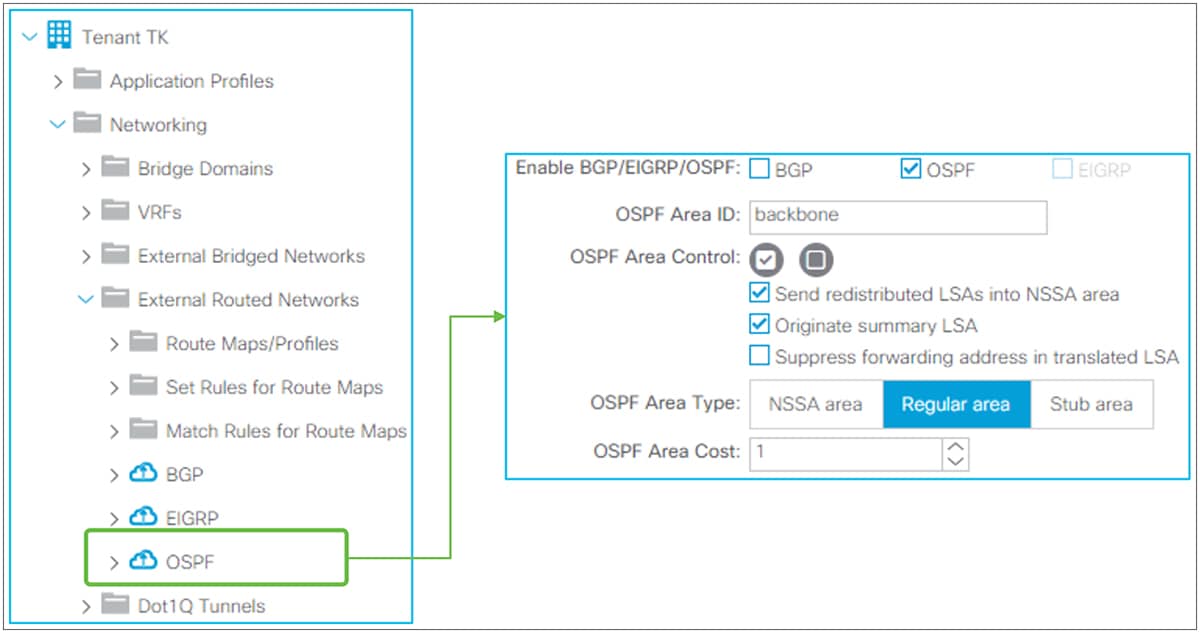
OSPF protocol options in GUI (APIC Release 3.2)
● OSPF Area ID
OSPF Area ID for all interfaces in this L3Out. Area 0 can be configured with a string “backbone” as well. Otherwise, use a number.
● OSPF Area Control
◦ Send Redistributed LSAs into NSSA area
This option is for the OSPF NSSA (not-so-stubby area). This is enabled by default to align with standard OSPF behavior. When this option is disabled, redistributed routes are not sent into this NSSA area from the border leaf. This is typically used when the Originate Summary LSA option is also disabled because disabling the Originate Summary LSA option creates and sends a default route to the NSSA or stub area.
The standalone NX-OS equivalent command for disabling this option is the following:
| router ospf 1 vrf TK:VRF1 area 0.0.0.1 nssa no-redistribution |
◦ Originate Summary LSA
This option is for OSPF NSSA or Stub area. This is enabled by default to align with standard OSPF behavior. When this option is disabled, not only Type 4 and 5, but also Type 3 LSAs are not sent into the NSSA or Stub area by the border leaf. Instead, the border leaf creates and sends a default route to the area. If there is no Type 3 LSA in this area in the first place, a default route is not created.
The standalone NX-OS equivalent command for disabling this option is the following:
| router ospf 1 vrf TK:VRF1 area 0.0.0.1 nssa no-summary |
◦ Suppress forwarding address in translated LSA
This option is for OSPF NSSA. This is disabled by default. An OSPF NSSA ABR (area border router) translates a Type-7 LSA into a Type-5, to send it across non-NSSA areas. At this time, the IP address of the originator ASBR (autonomous system boundary router) of the redistributed route is added to the LSA as a forwarding address. Under some circumstances, an OSPF router that receives a Type-5 LSA may not have a route to the forwarding address IP, and this blocks the Type 5’s route from being installed in the route table on the router. This can be avoided by enabling this option, which keeps the ACI border leaf (OSPF NSSA ABR) from adding a forwarding address to the LSA when it does a Type 7 to Type 5 translation.
This option was introduced in APIC Release 1.2(2).
The standalone NX-OS equivalent command for enabling this option is the following:
| router ospf 1 vrf TK:VRF1 area 0.0.0.1 nssa translate type7 suppress-fa |
● OSPF Area Type
ACI supports all three OSPF area types: Regular, NSSA, and Stub area.
● OSPF Area Cost
This option sets an OSPF Cost for a default route generated by the border leaf, such when the border leaf is a OSPF Stub area that generates a default route.
The standalone NX-OS equivalent command for enabling this option is the following:
| router ospf 1 vrf TK:VRF1 area 0.0.0.1 default-cost <cost> |
OSPF protocol options – VRF level
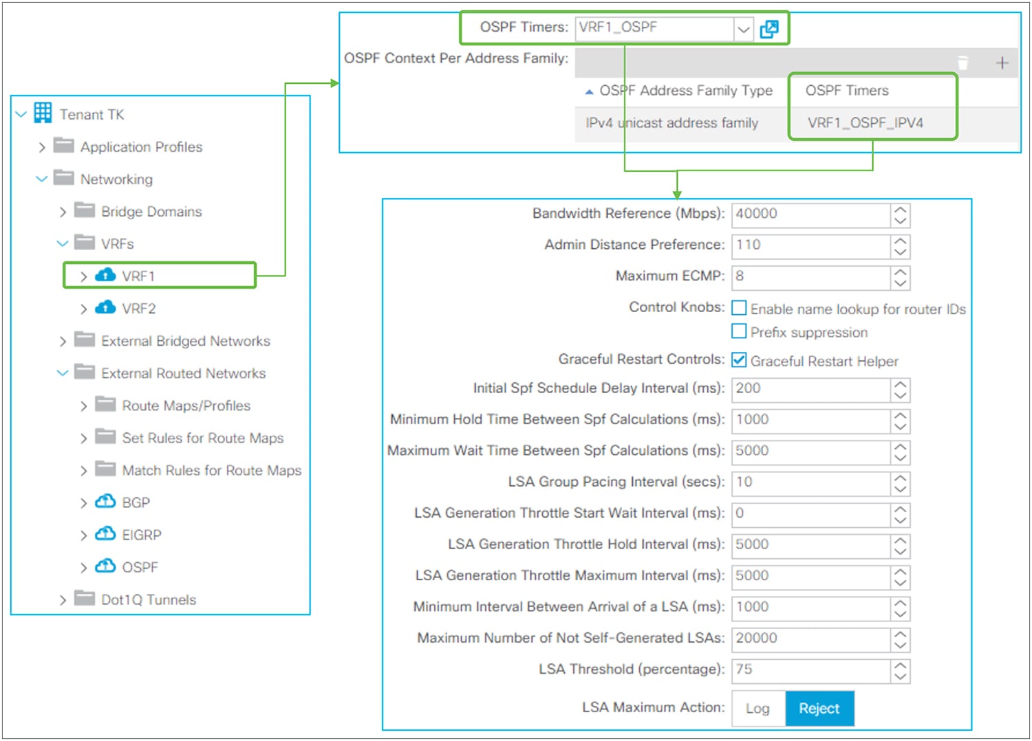
OSPF timer policy (per VRF and per address family)
This policy is used under VRF but the OSPF Timer Policy itself is located under “Tenant > Policies > OSPF > OSPF Timers”. When configured per VRF instead of per Address Family, the policy is applied to both OSPFv2 and OSPFv3. When configured per Address Family, the policy is applied only to the address family (that is, if the address family is IPv4, the policy is applied to OSPFv2). Per-Address-Family policy is preferred to per-VRF policy when both are configured.
Despite its name, OSPF Timer Policy has some configuration parameters other than timers. See the following for each parameter.
● Bandwidth Reference (Mbps)
The reference bandwidth used to calculate the default metrics for an OSPF interface. The default is 40,000 Mbps (40 Gbps).
The standalone NX-OS equivalent command is the following:
| router ospf 1 vrf TK:VRF1 auto-cost reference-bandwidth <number> Mbps |
● Admin Distance Preference
The administrative distance (AD) for OSPF. The default is 110.
The standalone NX-OS equivalent command is the following:
| router ospf 1 vrf TK:VRF1 distance <number> |
● Maximum ECMP
The maximum number of ECMP that OSPF can install into the routing table. The default is 8 paths.
The standalone NX-OS equivalent command is the following:
| router ospf 1 vrf TK:VRF1 maximum-paths <number> |
● Control Knobs
These two knobs were introduced in APIC Release 1.2(2).
◦ Enable name lookup for router IDs
To display the router IDs as DNS names in OSPF show commands. Disabled by default.
The standalone NX-OS equivalent command is the following:
| router ospf 1 vrf TK:VRF1 name-lookup |
◦ Prefix suppression
This option is to minimize the number of routes to be advertised or installed in the routing table. Disabled by default. When enabled, the following suppressions takes place:
Type-1 LSA: A link type “Link connected to: a Stub Network” from a self-generated Type-1 LSA, which represents a connected subnet for the point-to-point link, is not advertised to neighbors.
Type-2 LSA: A self-generated LSA with an LS type “Network Links”, which represents a connected subnet for the broadcast link, is advertised with /32 Network Mask instead of the real network mask. On a platform that supports prefix suppression, this /32 LSA is not installed in the routing table.
There is no standalone NX-OS equivalent command. Instead, the IOS equivalent command is the following:
| router ospf 1 prefix-suppression |
● Graceful Restart Control (Graceful Restart Helper)
When an OSPF router triggers a Graceful Restart, it sends an opaque LSA in OSPFv2 or a grace LSA in OSPFv3 to its neighbors. This LSA includes a grace period, which is a time that the neighbor interface holds on to the LSAs from the restarting router. The neighbor that receives a grace period from the restarting router is called a Graceful Restart Helper. ACI provides only a Graceful Restart Helper capability. During the graceful period, a graceful restart helper keeps all of the LSAs that originated from the restarting router.
There is no standalone NX-OS equivalent command. The command to enable both graceful restart router and helper capabilities at the same time on standalone NX-OS is the following:
| router ospf 1 vrf TK:VRF1 graceful-restart |
● Initial SPF Schedule Delay Interval (ms)
● Minimum Hold Time Between SPF Calculations (ms)
● Maximum Wait Time Between SPF Calculations (ms)
The standalone NX-OS equivalent command for SPF calculation timers is the following:
| router ospf 1 vrf TK:VRF1 timers throttle spf <initial delay> <minimum hold> <maximum wait> |
● LSA Group Pacing Interval (sec)
The standalone NX-OS equivalent command for LSA Group Pacing is the following:
| router ospf 1 vrf TK:VRF1 timers lsa-group-pacing <msec> |
● LSA Generation Throttle Start Wait Interval (ms)
● LSA Generation Throttle Hold Interval (ms)
● LSA Generation Throttle Maximum Interval (ms)
The standalone NX-OS equivalent command for LSA generation timers is the following:
| router ospf 1 vrf TK:VRF1 timers throttle lsa <start> <hold> <maximum> |
● Minimum Interval Between Arrival of a LSA (ms)
The standalone NX-OS equivalent command for a minimum LSA Arrival Interval is the following:
| router ospf 1 vrf TK:VRF1 timers lsa-arrival <msec> |
● Maximum Number of Not Self-Generated LSAs
● LSA Threshold (percentage)
● LSA Maximum Action (Log or Reject)
The standalone NX-OS equivalent command for minimum LSA Arrival Interval is the following:
| router ospf 1 vrf TK:VRF1 max-lsa <max lsa> <threshold> {warning-only} |
This feature was introduced in APIC Release 1.2(2). This feature is to advertise only a summarized prefix for BD subnets and/or Transit Routes from ACI OSPF L3Out to outside. In OSPF, ACI supports two summarization methods.
● Redistributed Route Summary: This is equivalent to “summary-address <prefix>/<mask>”.
● Inter-area Route Summary: This is equivalent to “area <ID> range <prefix>/<mask>”.
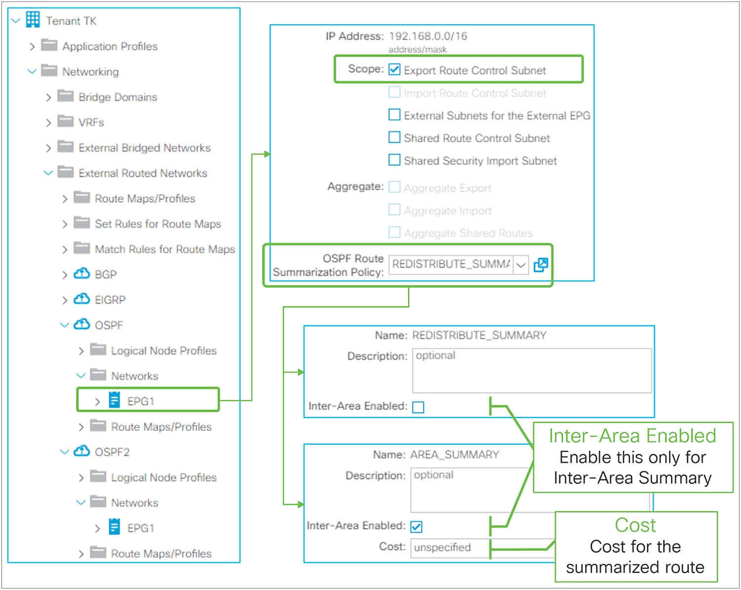
OSPF route summarization in GUI (APIC Release 3.2)
OSPF route summarization in ACI is configured by adding a route summarization policy to an L3Out subnet with scope “Export Route Control Subnet”, because it is to advertise (export) routes from ACI to outside. Please refer to the “L3Out Transit Routing” section for details about the “Export Route Control Subnet” scope.
By adding a route summarization policy to the L3Out subnet as shown in Figure 54, the border leaf will try to create a Null-0 entry for the summarized route (192.168.0.0/16 in Figure 54), which will be advertised to its OSPF peers. This summarized route with a Null-0 next-hop will not be advertised to other leaf switches via infra MP-BGP. Please be aware that, just as for a normal OSPF router, the summarization will not occur if no contributing routes exist in the OSPF database for the VRF on the border leaf.
Unlike BGP or EIGRP, there is one exceptional scenario where OSPF does not use redistribution to advertise routes to outside. That is when performing Transit Routing between two OSPF L3Outs on the same border leaf (please refer to the “L3Out Transit Routing” section for details). Hence, ACI supports two methods of OSPF route summarization, as mentioned above. The detailed configuration guidance and topology for both summarization methods are as follows:
OSPF Route Summarization – Redistributed Routes
Redistributed Route Summarization is used for all OSPF summarizations except one, when there are two OSPF L3Outs on the same border leaf. OSPF Redistributed Route Summarization (192.168.0.0/16 in Figure 54 and Figure 55) uses OSPF Route Summarization Policy without the “Inter-Area Enabled” option. Without the option, this will be equivalent to “summary-address 192.168.0.0/16” in standalone NX-OS. It will try to summarize all routes within the configured subnet (192.168.0.0/16 in Figure 54 or Figure 55) from Type-5 or Type-7 LSA, which are redistributed external routes. If there is no LSA that can be summarized in this way, summarization does not happen, and no Null-0 entry for 192.168.0.0/16 is created. This means that at least one subnet needs to be redistributed into the OSPF L3Out (L3Out 3 in Figure 55) explicitly for OSPF summarization to happen.
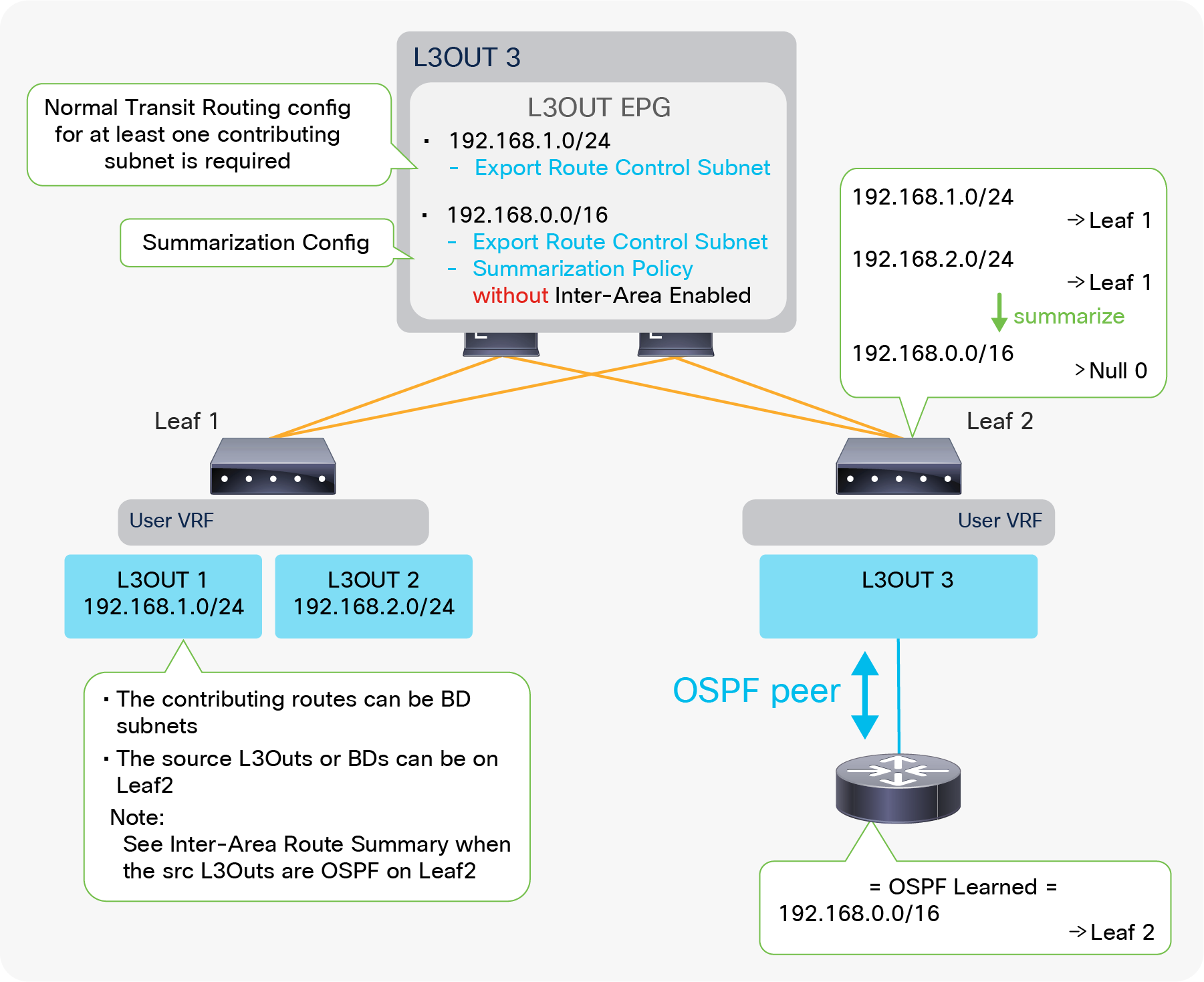
Example of OSPF route-summarization topology (redistribute routes)
Figure 55 depicts when L3Out 3 advertises only a summarized subnet (192.168.0.0/16) for transit routes from L3Out 1 and 2 (192.168.1.0/24 and 192.168.2.0/24). To perform a summarization, at least one contributing subnet needs to be in the OSPF LSDB for L3Out 3. Hence, a Transit Routing configuration (“Export Route Control Subnet” scope) for at least one contributing subnet is required in Figure 55. If it is summarizing BD subnets, a correct BD subnet advertisement configuration is required for at least one subnet (see the “ACI BD subnet advertisement” section).
The standalone NX-OS equivalent commands are the following:
| router ospf 1 vrf TK:VRF1 summary-address <prefix>/<mask> |
OSPF Route Summarization – Inter-Area Routes
When there are multiple OSPF L3Outs on the same border leaf, each L3Out manages a different OSPF area. Hence, Transit Routing between those L3Outs will not use redistribution but will use area-filter instead. In such a scenario, route summarization cannot be performed using the previous option because the previous summarization option is for redistributed Type-5 and Type-7 LSAs. To address this, ACI offers Inter-Area Route Summarization as well.
| Note: If multiple OSPF L3Outs are deployed on different border leaf switches instead of on the same border leaf, then one OSPF L3Out will get the transit routes from another OSPF L3Out via infra MP-BGP. Hence it still uses redistribution and relies on Redistributed Route Summarization instead of Inter-Area Route Summarization. Please see the “L3Out Transit Routing” section for details about how OSPF L3Out implements Transit Routing. |
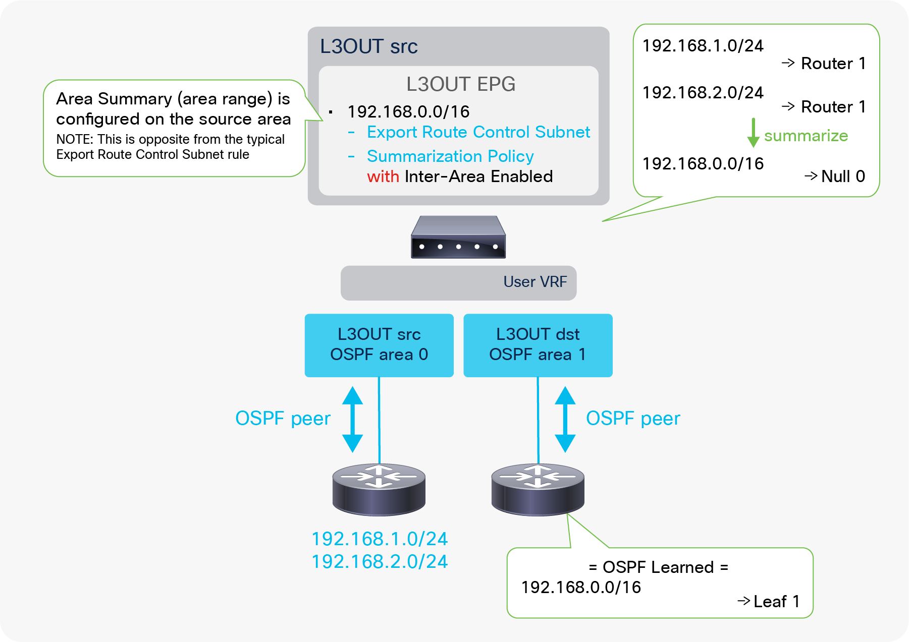
Example of OSPF route-summarization topology (inter-area routes)
The OSPF Inter-Area Route Summarization uses OSPF Route Summarization Policy with an “Inter-Area Enabled” option. With this option, this will be equivalent to “area 0 range 192.168.0.0/16” in standalone NX-OS. Since the area-range command is configured on the source area that has routes to be summarized, this configuration on ACI is also configured on the source L3Out (“L3Out src” in Figure 56) unlike any other L3Out route summarization. Assuming the source L3Out is learning routes to be summarized (192.168.x.0/24 in Figure 56), the summarization takes place without any additional ACI configurations, and the summarized route (192.168.0.0/16 in Figure 56) will be advertised to the outside from the destination L3Out (L3Out dst).
| Note: If there are other OSPF L3Outs on the same border leaf in the same VRF, the summarized route will be advertised from all of them except the source L3Out. This is because the area-filter, which controls transit routes between OSPF L3Outs (the OSPF areas) on the same border leaf, uses the same route map for all OSPF L3Outs on the same leaf in the same VRF. In this shared route map for the area-filter, the summarized prefix (192.168.0.0/16 in Figure 56) is allowed due to the “Export Route Control Subnet” scope in the source L3Out. This means all L3Outs on the same border leaf in the same VRF tries to allow the summarized prefix due to the shared route map. This is also the reason no configuration is required on the destination L3Outs. Please see “Internal route-map for Transit Routing” in the “L3Out Transit Routing” section for details. |
| Note: This is a very exceptional usage of the “Export Route Control Subnet” scope because the scope is typically configured on the destination L3Out (“L3Out dst” in this example), from which routes need to be advertised (exported) to the outside. Please see the “L3Out subnet scope options” section or the “L3Out Transit Routing” section for a description of the normal usage of “Export Route Control Subnet”. |
For Inter-Area Route Summarization, a cost can be configured for the summarized route. If not specified, the source L3Out with the summarization policy uses the maximum cost from the contributing routes, which is the method defined in RFC 2328 to get the cost of summarized routes.
The standalone NX-OS equivalent commands are the following:
| router ospf 1 vrf TK:VRF1 area <source area id> range <prefix>/<mask> {cost <num>} |
OSPF default-route advertisement
There are multiple methods to advertise a default route (0.0.0.0/0) from OSPF L3Out to the outside. This subsection covers the basics of Default Route Leak Policy in OSPF, then provides a summary of methods used for each OSPF area type. Please remember that Default Route Leak Policy is not always the answer for advertising a default route in OSPF. For example, it does not do anything for the OSPF Stub area because Default Route Leak Policy is essentially the same as “default-information originate” or “area <ID> nssa default-information-originate.” Thus, an understanding of standard OSPF area behavior is required.
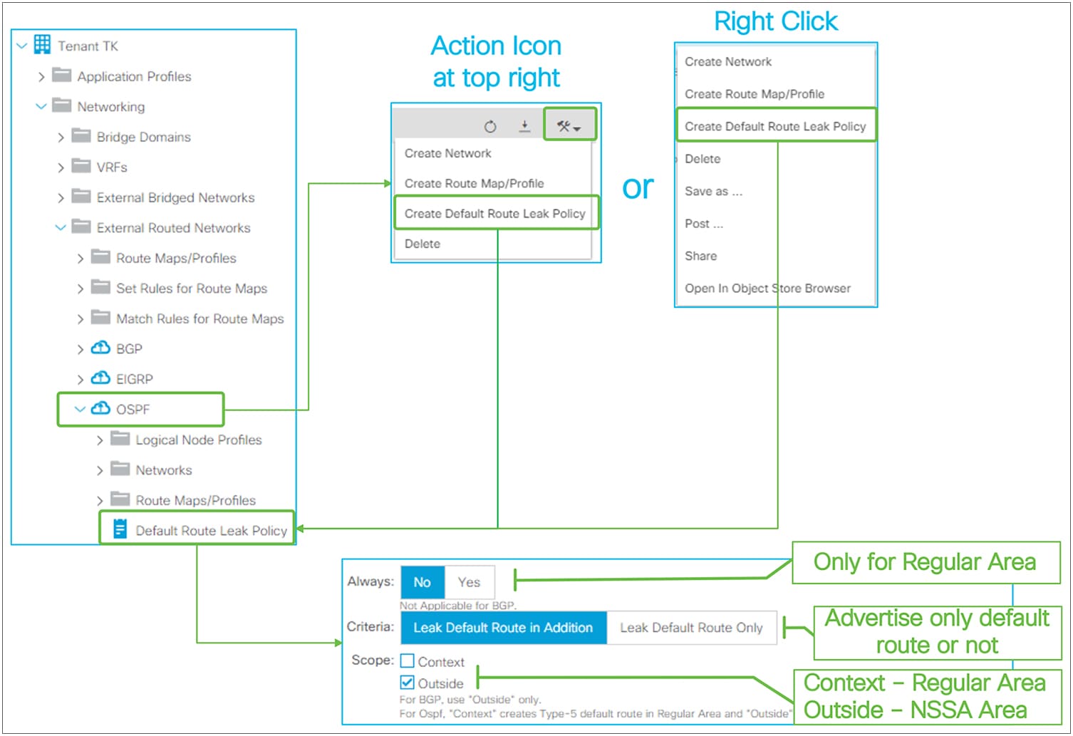
Default Route Leak Policy for OSPF in GUI (APIC Release 3.2)
Default Route Leak Policy was introduced in APIC Release 1.1(1) and can be created under an L3Out in either of the following ways:
● Choose “Create Default Route Leak Policy” from a dropdown menu at the top right in L3Out
● Choose “Create Default Route Leak Policy” from a right-click menu on L3Out itself
Default Route Leak Policy has the following parameters:
● Always
This is applicable only for OSPF Regular area. If Always is set to Yes, a default route will be created in OSPF LSDB even if there is no default route in the routing table.
● Criteria
Use “Leak Default Route in Addition” when a default route needs to be advertised on top of other routes. Use “Leak Default Route Only” when only a default route should be advertised.
When “Leak Default Route Only” is selected, deny-all is applied to route maps for all redistribution and area-filter in this L3Out to prevent other routes from being advertised.
● Scope
Choose “Context” for OSPF Regular area. Choose “Outside” for OSPF NSSA area.
The standalone NX-OS equivalent command for OSPF Regular area is the following:
| router ospf 1 vrf TK:VRF1 default-information originate [always] |
The standalone NX-OS equivalent command for OSPF NSSA area is the following:
| router ospf 1 vrf TK:VRF1 area 0.0.0.1 nssa default-information-originate |
Default route in OSPF Stub area
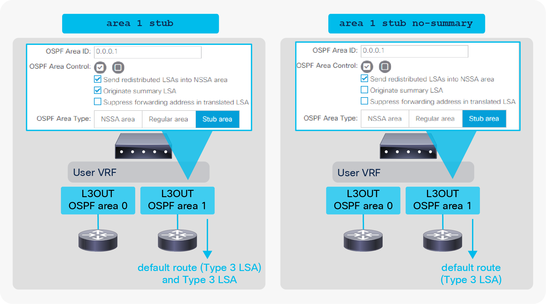
Default-route advertisement in OSPF Stub area
● Default Stub Behavior (the left side in Figure 58)
By default, the OSPF ABR will generate a default route, and send it along with other Type-3 LSAs into the Stub area.
● Totally Stub Behavior (the right side in Figure 58)
By disabling the “Originate Summary LSA” option under the root of L3Out, the Stub area becomes a totally Stub area. Then a default route is generated, and only the default route will be advertised.
Default route in OSPF NSSA area
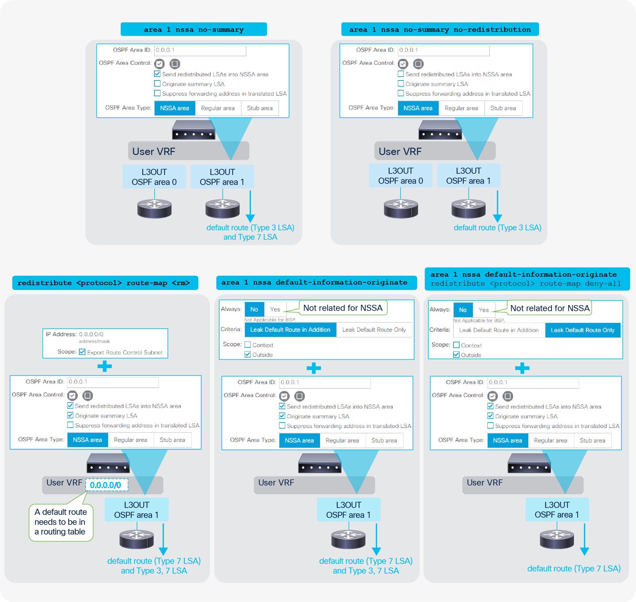
Default-route advertisement in OSPF NSSA area
● Totally NSSA Behavior (the top 2 diagrams)
By disabling the “Originate Summary LSA” option under the root of L3Out, the NSSA area becomes a totally NSSA area. Then a default route is generated and other Type-3 LSAs will be suppressed. Type-7 LSAs can be advertised on top of the default route when a border leaf is ASBR and ABR at the same time. This Type-7 LSA can also be suppressed by disabling the “Send redistributed LSAs into NSSA area” option.
● Transit Routing (the diagram on the bottom left)
This option is to export a default route from another L3Out or static route via the “Export Route Control Subnet” scope. See the “L3Out Transit Routing” section for details.
● Default Route Leak Policy (the two diagrams on the bottom right)
This option is to use Default Route Leak Policy in L3Out. See above for the Default Route Leak Policy itself.
Default route in OSPF Regular area
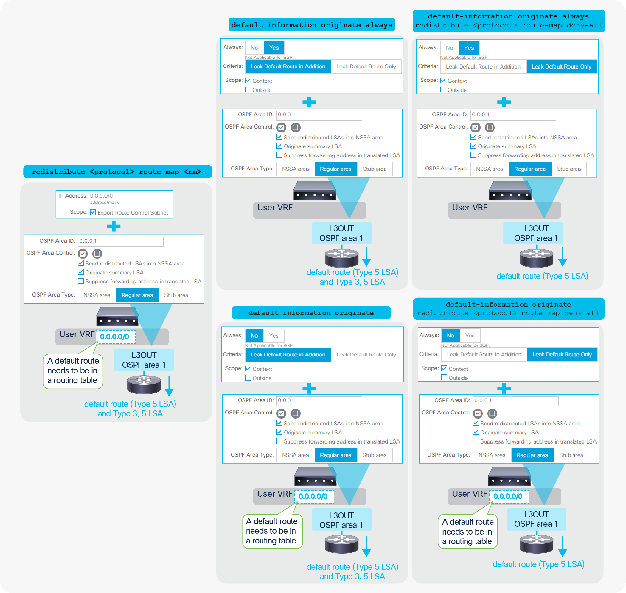
Default-route advertisement in OSPF Regular area
● Transit Routing (the diagram on the left)
This option is to export a default route from another L3Out via the “Export Route Control Subnet” scope. See the “L3Out Transit Routing” section for details.
● Default Route Leak Policy (the four diagrams on the right)
This option is to use Default Route Leak Policy in L3Out. See above for the Default Route Leak Policy itself.
| Note: When Default Route Leak Policy is configured with Context scope on one L3Out, it will be applied to all L3Outs with OSPF Regular Area in the same VRF on the same border leaf. This is equivalent to “default-information originate” from standard NX-OS where it applies to all regular areas in a VRF. |
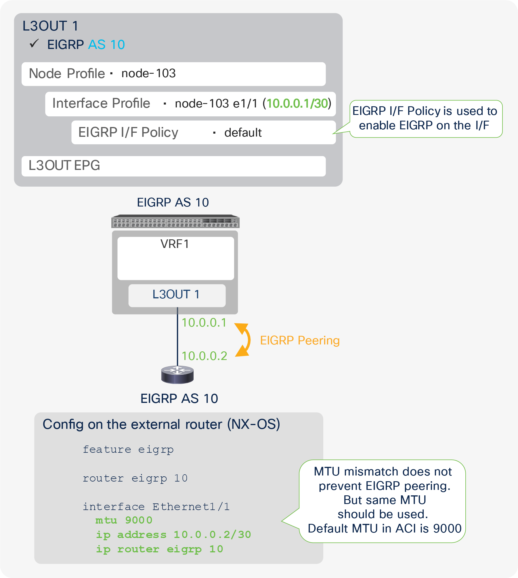
Figure 61 illustrates an example configuration of EIGRP with AS 10. The key component is the same as a normal router, to ensure that the AS number matches. Although the MTUs are not required to be the same for EIGPR neighborship, the recommendation is to set the same values to ensure that any protocol packets such as the routes exchange after establishing neighborship will not be dropped.
Figure 62 shows an example of an APIC GUI configuration.
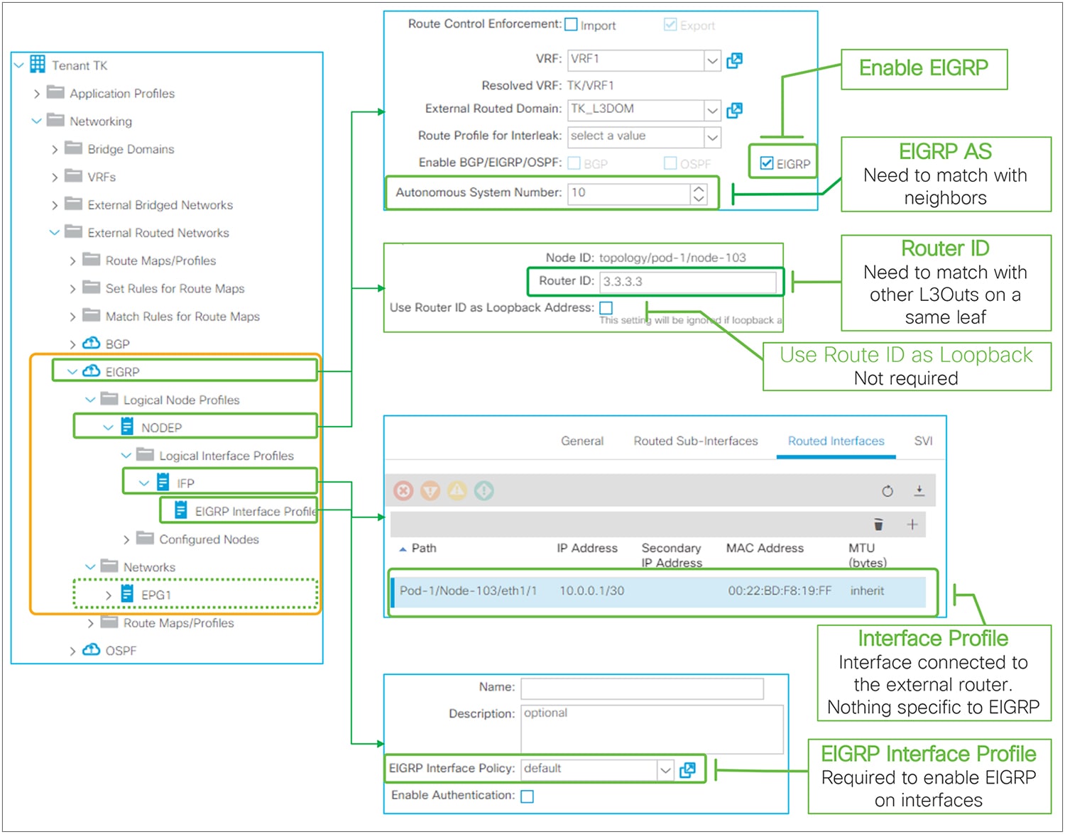
EIGRP basic configuration in GUI (APIC Release 3.2)
The following are the three EIGRP-specific components:
● Enable EIGRP: Check to enable EIGRP protocol on the border leaf switches in the L3Out.
● EIGRP AS Number: EIGRP AS Number used to establish a neighbor.
● EIGRP Interface Profile: To enable EIGRP on interfaces in the Logical I/F Profile. A default can be used unless fine tuning is required.
Just as with a normal router, a loopback is not specifically required for EIGRP to work.
● EIGRP (IPv4) has been supported since APIC Release 1.1(1).
● EIGRP (IPv6) has been supported since APIC Release 1.2(2).
● Only one EIGRP L3Out can be deployed on a border leaf per VRF. This is because one EIGRP L3Out represents one EIGRP AS.
● When multiple external routers are connected to an EIGRP L3Out with the same VLAN, which means in the same L3Out BD, external routers will form neighbors directly to each other. See Figure 20 in the “L3Out bridge domain” subsection in the “L3Out Node and Interface Profiles” section for details.
In such a scenario, external routers will exchange routes directly through the ACI L3Out BD. Hence, a situation similar to Transit Routing with “Export Route Control Subnet” could occur without “Export Route Control Subnet”.
● When advertising a BD subnet or performing Transit Routing, routes are redistributed into the EIGRP topology via a route map that is automatically created on a border leaf. This route map is shared with OSPF L3Outs on the same leaf in the same VRF. It implies that the subnet advertisement configuration on one L3Out may affect other L3Outs. Hence, awareness of this implementation is required when there are other L3Outs on the same leaf in the same VRF. See Figure 93 in the “L3Out Transit Routing” section for details.
Please check the “EIGRP protocol support” section in the Cisco APIC Layer 3 Network Configuration Guide for other limitations.
EIGRP protocol options – interface level
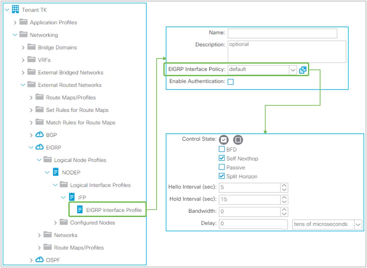
EIGRP Interface Profile and Policy in GUI (APIC Release 3.2)
Interface level EIGRP configuration from the EIGRP Interface Profile is applied to all interfaces in the associated Logical Interface Profile. The EIGRP Interface Policy itself is located under “Tenant > Policies > EIGRP > EIGRP Interface”.
EIGRP Interface Policy
● Control State
◦ BFD
This feature was introduced in APIC Release 1.2(2). It is used to enable BFD on the EIGRP Interface. See the “L3Out BFD” section for details.
The standalone NX-OS equivalent command is the following:
| interface eth1/1 |
◦ Self Nexthop
This option is enabled by default. By default, EIGRP sets its local IP address as the next-hop when advertising routes. By disabling this option, the border leaf does not overwrite the next-hop and keeps the original next-hop IP.
The standalone NX-OS equivalent command is the following:
| interface eth1/1 ip next-hop-self eigrp <instance> |
◦ Passive
This option is to configure the interfaces as an EIGRP passive interface. This option is disabled by default.
The standalone NX-OS equivalent command is the following:
| interface eth1/1 ip passive-interface eigrp <instance> |
◦ Split Horizon
Split Horizon is a feature to prevent a routing loop by not sending EIGRP updates or queries to the interface where it was learned. This option is enabled by default.
The standalone NX-OS equivalent command is the following:
| interface eth1/1 ip split-horizon eigrp <instance> |
● Hello Interval (sec) / Hold Interval (sec)
The Hello Interval is the interval for EIGRP Hello messages to be sent. The default is 5 seconds. The Hold Interval is advertised in Hello messages and indicates to neighbors the length of time that they should consider the sender valid. The default Hold Interval is three times the Hello Interval, which is 15 seconds.
The standalone NX-OS equivalent commands are the following:
| interface eth1/1 ip hello-interval eigrp <instance> <sec> ip hold-interval eigrp <instance> <sec> |
● Bandwidth / Delay
Configures the bandwidth and delay for the EIGRP metric calculation.
The standalone NX-OS equivalent commands are the following:
| interface eth1/1 ip bandwidth eigrp <instance> <bandwidth> ip delay eigrp <instance> <delay> |
EIGRP Authentication
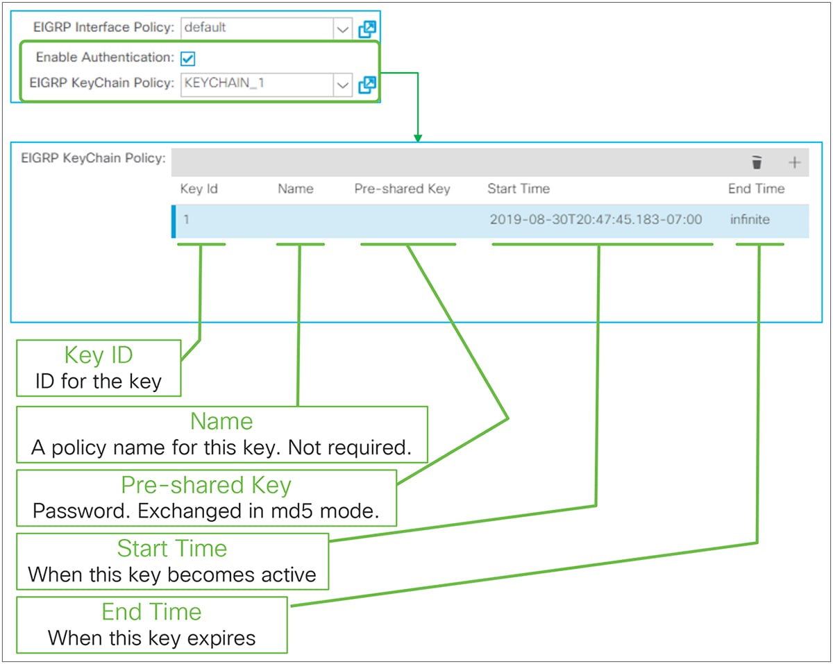
EIGRP key authentication in GUI (APIC Release 3.2)
EIGRP Authentication was introduced in APIC Release 3.2(4) though this enhancement;
CSCvk43721 EIGRP Authentication support for ACI
It is enabled per EIGRP Interface Profile with KeyChain. The supported EIGRP authentication mode is MD5.The EIGRP KeyChain Policy itself is located under “Tenant > Policies > EIGRP > EIGRP KeyChains”.
● Key ID: ID for the key to manage multiple keys in the key chain.
● Name: A name used in an object model for each key. Optional.
● Pre-shared Key: A password that needs to match with its neighbors.
● Start Time: A time when this key becomes active. If empty, it starts immediately.
● End Time: A time when this key expires. If empty, infinite is used.
The standalone NX-OS equivalent commands are the following:
| key chain <keychain name> key <id> key-string <password> send-lifetime <start-time> <end-time>
interface eth1/1 ip authentication mode eigrp <instance> md5 ip authentication key-chain eigrp <instance> <keychain name> |
EIGRP protocol options – VRF level
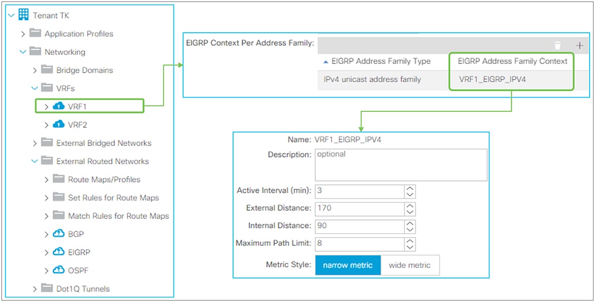
EIGRP Address Family Context Policy in GUI (APIC Release 3.2)
EIGRP Address Family Context Policy
This policy is used under VRF but the EIGRP Address Family Context Policy itself is located under “Tenant > Policies > EIGRP > EIGRP Address Family Context”.
The details for each parameter are as follows:
● Active Interval (min)
This is the interval the border leaf waits after sending an EIGRP query before declaring stuck in active (SIA) and resetting the neighborship. The default is 3 minutes.
The standalone NX-OS equivalent commands are the following:
| router eigrp 10 vrf TK:VRF1 address-family ipv4 unicast timers active-time <min> |
● External Distance / Internal Distance
Administrative distance (AD) for external and internal EIGRP routes. The default is 170 for external, 90 for internal.
The standalone NX-OS equivalent command are the following:
| router eigrp 10 vrf TK:VRF1 address-family ipv4 unicast distance <internal> <external> |
● Maximum Path Limit
The maximum number of ECMPs that EIGRP can install into the routing table. The default is eight paths.
The standalone NX-OS equivalent commands are the following:
| router eigrp 10 vrf TK:VRF1 address-family ipv4 unicast maximum-paths <num> |
● Metric Style
EIGRP calculates its metric based on bandwidth and delay along with default K values. However, the original implementation value of 32 bits cannot differentiate interfaces faster than 10 Gigabit Ethernet. This original implementation is called the classic or narrow metric. To solve this problem, a value of 64 bits with an improved formula was introduced for EIGRP. This is called the wide metric. The default is the narrow metric.
The standalone NX-OS equivalent commands are the following:
| router eigrp 10 vrf TK:VRF1 address-family ipv4 unicast metric version 64bit |
This feature was introduced in APIC Release 1.2(2). This feature is to advertise only a summarized prefix for BD subnets and/or Transit Routes from ACI OSPF L3Out to the outside.
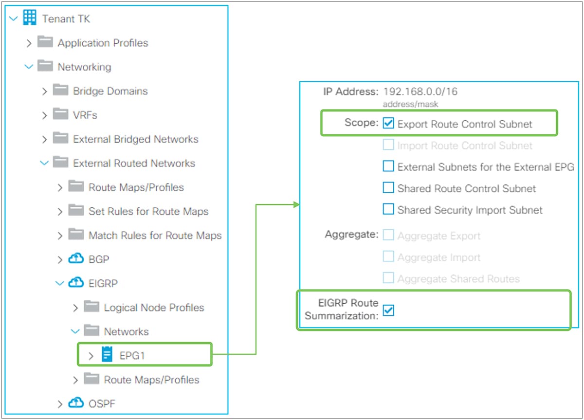
EIGRP Route Summarization in GUI (APIC Release 3.2)
EIGRP Routing Summarization in ACI is configured by adding a route summarization policy to an L3Out Subnet with the scope “Export Route Control Subnet” because it is to advertise (export) routes from ACI to the outside. Please refer to the “L3Out Transit Routing” section for details about the “Export Route Control Subnet” scope.
By adding a route summarization policy to the L3Out subnet, as shown in Figure 66, the border leaf will try to create a Null-0 entry for the summarized route (192.168.0.0/16 in Figure 66), which will be advertised to its EIGRP peers. This summarized route with a Null-0 next-hop will not be advertised to other leaf switches via infra MP-BGP. Please be aware that, as in a normal EIGRP router, the summarization will not occur if no contributing routes exist in the EIGRP topology table for the user VRF on the border leaf.
EIGRP summarization is implemented per interface. Hence, ACI will deploy the summarization policy on all interfaces in the L3Out.
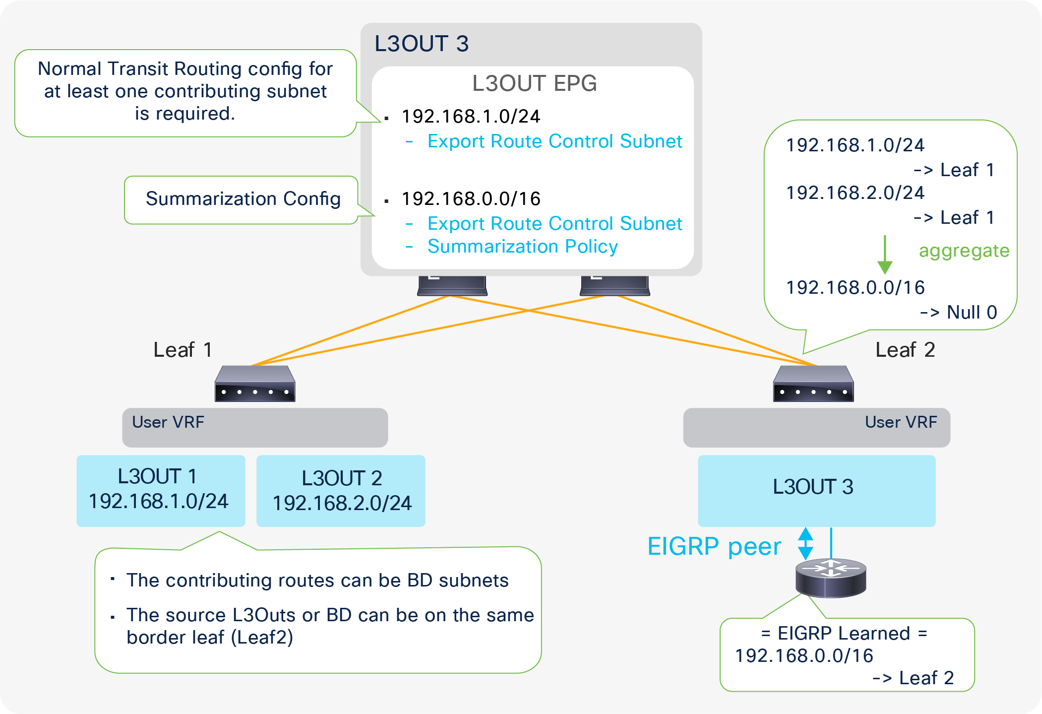
Example of an EIGRP Route Summarization topology
Figure 67 depicts when L3Out 3 advertises only a summarized subnet (192.168.0.0/16) for transit routes from L3Out 1 and 2 (192.168.1.0/24 and 192.168.2.0/24). To perform a summarization, at least one contributing subnet needs to be in the EIGRP topology table for L3Out 3. Hence, a Transit Routing configuration (with an “Export Route Control Subnet” scope) for at least one contributing subnet is required. If it is summarizing BD subnets, a correct BD subnet advertisement configuration is required for at least one subnet (see the “ACI BD subnet advertisement” section).
The standalone NX-OS equivalent command is the following:
| interface eth1/1 ip summary-address eigrp <instance> <prefix>/<mask> |
| Note: When OSPF Route Summarization is configured on the same leaf in the same VRF as EIGRP L3Out, the OSPF summarized route will be advertised to EIGRP as well, even without any route summarization in the EIGRP L3Out. This is because of the following: 1. The summarized route with a Null-0 next-hop was already created in the routing table due to OSPF on the same border leaf. 2. The OSPF L3Out creates a route-map entry for the summarized route. 3. This route map is for Transit Routing or an “Export Route Control Subnet” scope; thus, it is shared between OSPF and EIGRP on the same leaf in the same VRF. Please see the Internal route-map for Transit Routing in the “L3Out Transit Routing” section for details. For these reasons, EIGRP redistributes the OSPF summarized route on the same leaf without EIGRP Route Summarization. The same will happen when EIGRP L3Out has a route-summarization configuration, but OSPF L3Out on the same leaf in the same VRF does not. |
EIGRP default route advertisement
There are two methods to advertise a default route (0.0.0.0/0) from EIGRP L3Out to the outside:
1. Transit Routing
2. Default Route Leak Policy
Transit Routing will advertise a default route that is learned from another L3Out or possibly a static route configured on another L3Out. See the “L3Out Transit Routing” section for details on Transit Routing.
Default Route Leak Policy is equivalent to “default-information originate” in standalone NX-OS.
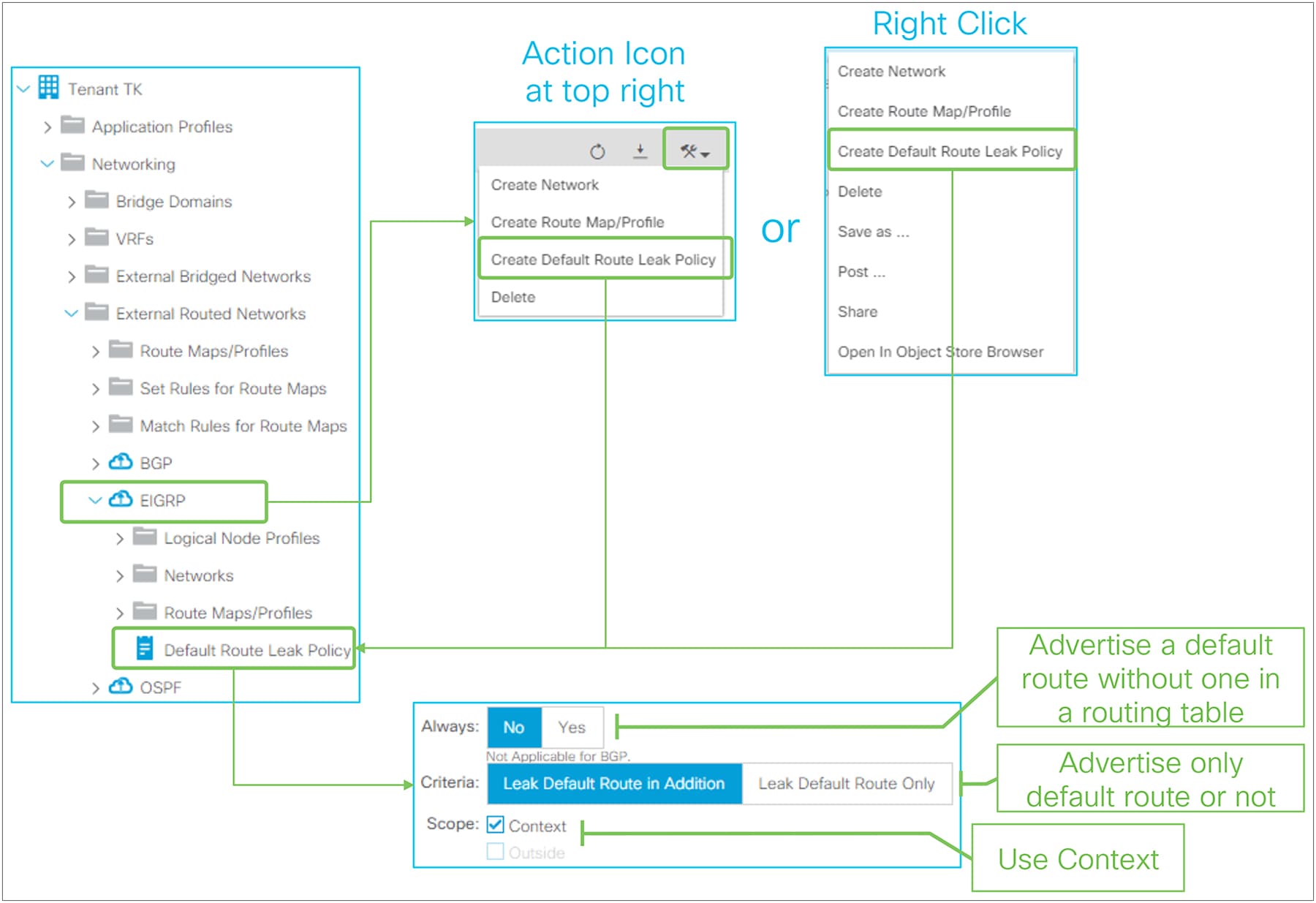
Default Route Leak Policy for EIGRP in GUI (APIC Release 3.2)
Default Route Leak Policy was introduced in APIC Release 1.1(1) and can be created under an L3Out by either of the following ways:
● Choose “Create Default Route Leak Policy” from a dropdown menu at the top right in L3Out
● Choose “Create Default Route Leak Policy” from a right-click menu on L3Out itself
Default Route Leak Policy has the following parameters:
● Always
This is equivalent to the “always” option for “default-information originate” in standalone NX-OS. If Yes, a default route is advertised even without a default route in a routing table.
● Criteria
Use “Leak Default Route in Addition” when a default route needs to be advertised on top of other routes. Use “Leak Default Route Only” when only a default route should be advertised.
When “Leak Default Route Only” is selected, no redistribution rule is deployed on a border leaf for this EIGRP L3Out.
● Scope
Use “Context” for EIGRP.
The standalone NX-OS equivalent commands are the following:
| router eigrp 10 vrf TK:VRF1 default-information originate [always] |
This section covers the details of how ACI fabric advertises BD subnets via a routing protocol in L3Out. Please refer to the “Basic components of L3Out” section for a basic understanding and configuration.
There are three methods to accomplish BD subnet advertisement:
1. Via L3Out association to a BD (the method explained in the “Basic components of L3Out” section)
2. Via an “Export Route Control Subnet” scope in a subnet under L3Out EPG
3. Via Route Map/Profile in Export Direction with an explicit prefix-list
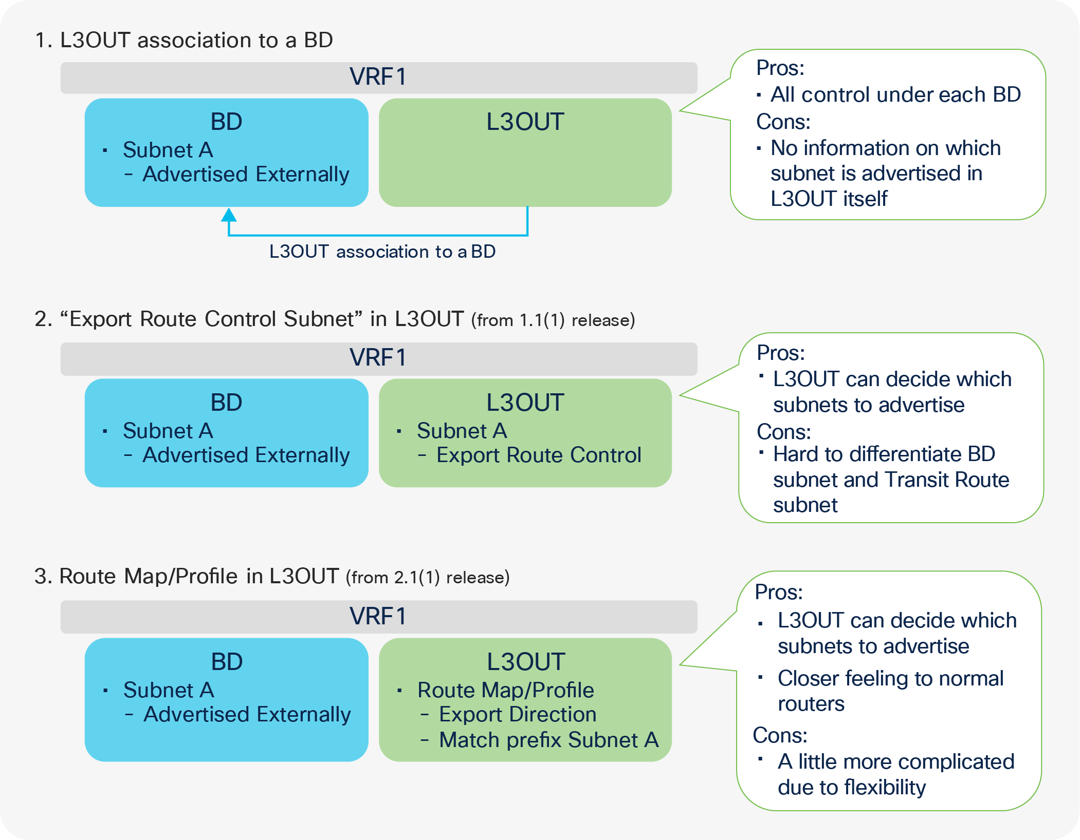
BD subnet advertisement methods
Figure 69 illustrates three methods to advertise BD subnet externally, with the pros and cons of each method. What is deployed on a leaf is the same for all three methods; ACI creates an IP prefix-list for a BD subnet (only if this subnet was configured with an “Advertised Externally” scope), and it inserts the prefix list into a route map on a border leaf (the details are explained below, in Figure 70 and Figure 71). Thus, it depends on the user’s preference which method to use. One simple recommendation is not to mix the three methods, because managing the mixed configuration will be very challenging.
The first method, L3Out association to a BD, is the most basic one and has been supported from the first APIC Release 1.0. It gives all controls solely to the BD (a) about which BD subnets are to be advertised (b) to which L3Out. In case the operation teams are separated between the BD and L3Out components, perhaps due to multitenancy, this method can be completed within a single team/component. On the other hand, the L3Out component itself has less visibility on which BD subnet it is advertising because the L3Out association to a BD is configured under the BD.
The second method, using an “Export Route Control Subnet” scope, allows the managing of subnets advertised to the outside via an L3Out configuration regardless of whether the subnets are BD subnets or external routes from another L3Out (Transit Routing). Although this may consolidate configurations, it may be confusing if you want to troubleshoot a configuration, and you need to distinguish BD subnets as opposed to Transit Routing subnets by looking at L3Out subnets. Please note that BD subnets still need to be marked as “Advertised Externally”.
The third method, using Route Map/Profile in Export Direction, provides a configuration methodology like that for a normal router when you configure a route map and an IP prefix-list directly. This option uses Route Profiles and Explicit Prefix Lists (match prefix criteria) instead of L3Out association to a BD or the L3Out Export Route Control Subnet. See the “L3Out Route Profile / Route Map” section for details. The same pros and cons of the second method apply to this one as well. BD subnets still need to be marked as “Advertised Externally”.
Internal route-map for BD subnet advertisement
This section explains the details of what actually happens on a border leaf to advertise a BD subnet.
For the BD subnets to be announced via the L3Out to the outside, APIC must configure the border leaf with three elements (depicted in different colors in Figure 70):
● A redistribution configuration with a route map (which may be empty in the beginning), depicted in green in the picture
● An IP prefix-list in the route map that contains the subnets that should be advertised (depicted in blue in the picture)
● The BD-subnet route pushed by APIC on the border leaf as a result of the contract between the L3Out external EPG and the EPG where the servers are (depicted in gray in the picture)
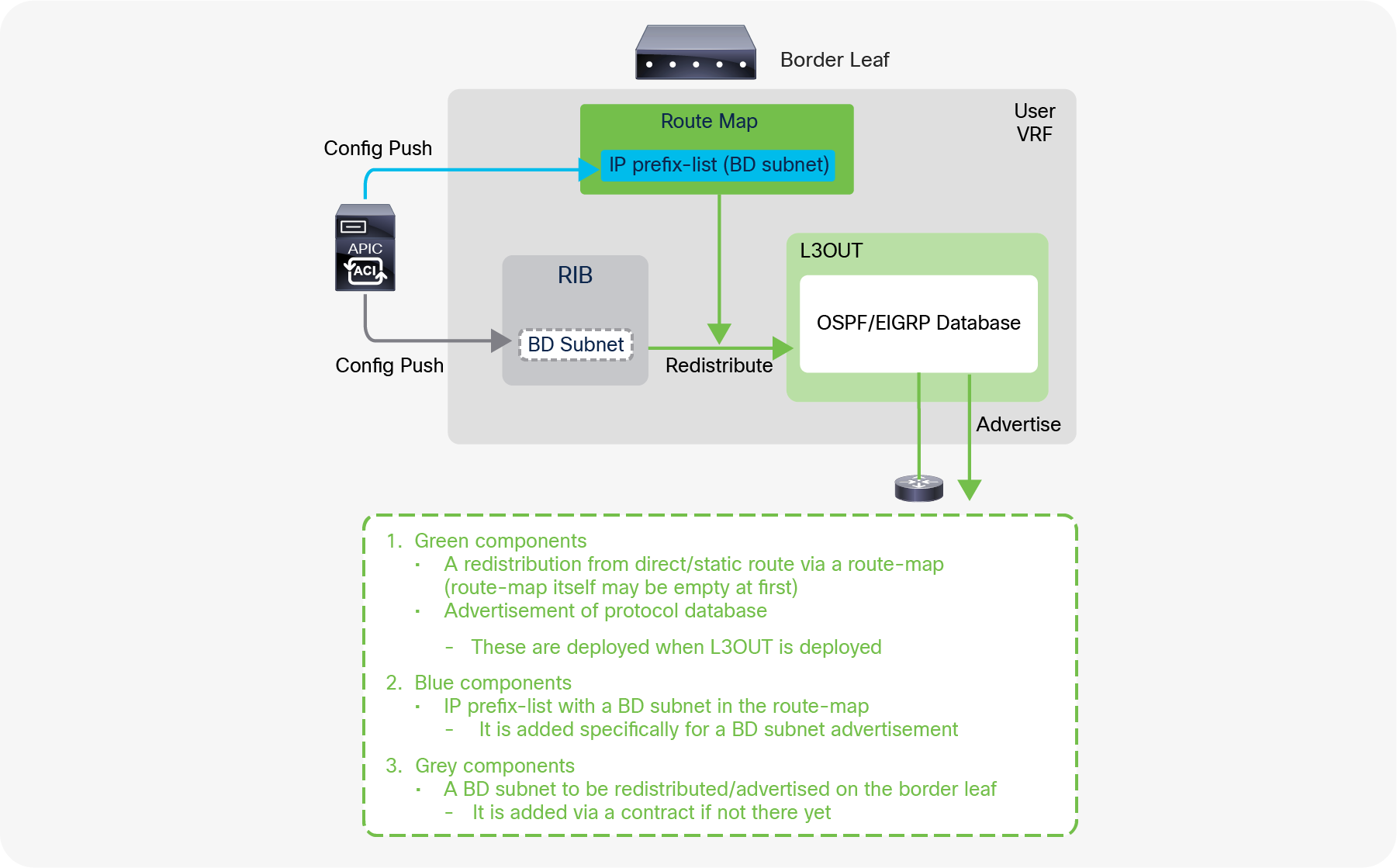
BD subnet advertisement architecture (OSPF/EIGRP)
Figure 70 explains what happens under the hood for BD subnet advertisement in OSPF and EIGRP. The green components (a route map for the redistribution from direct/static routes and advertisement of routes in the protocol database) are deployed on a border leaf regardless of whether BD subnets are configured to be advertised or not. However, without the BD subnets configured to be advertised (for instance, if there is no L3Out association to a BD), the route map for the direct/static redistribution is empty, and the BD subnet advertisement has yet to be accomplished. The blue component (the IP prefix-list for the BD subnet in the route map) is what is actually added by the BD subnet advertisement configuration, such as the L3Out association to a BD. With this, the BD subnet can be redistributed into a routing protocol and advertised to the outside if the BD subnet is deployed on the border leaf. The BD subnet can be present on the border leaf as a result of a contract between the L3Out External EPG and the EPGs for the BD, or simply because there are local endpoints attached to the BD on the border leaf.
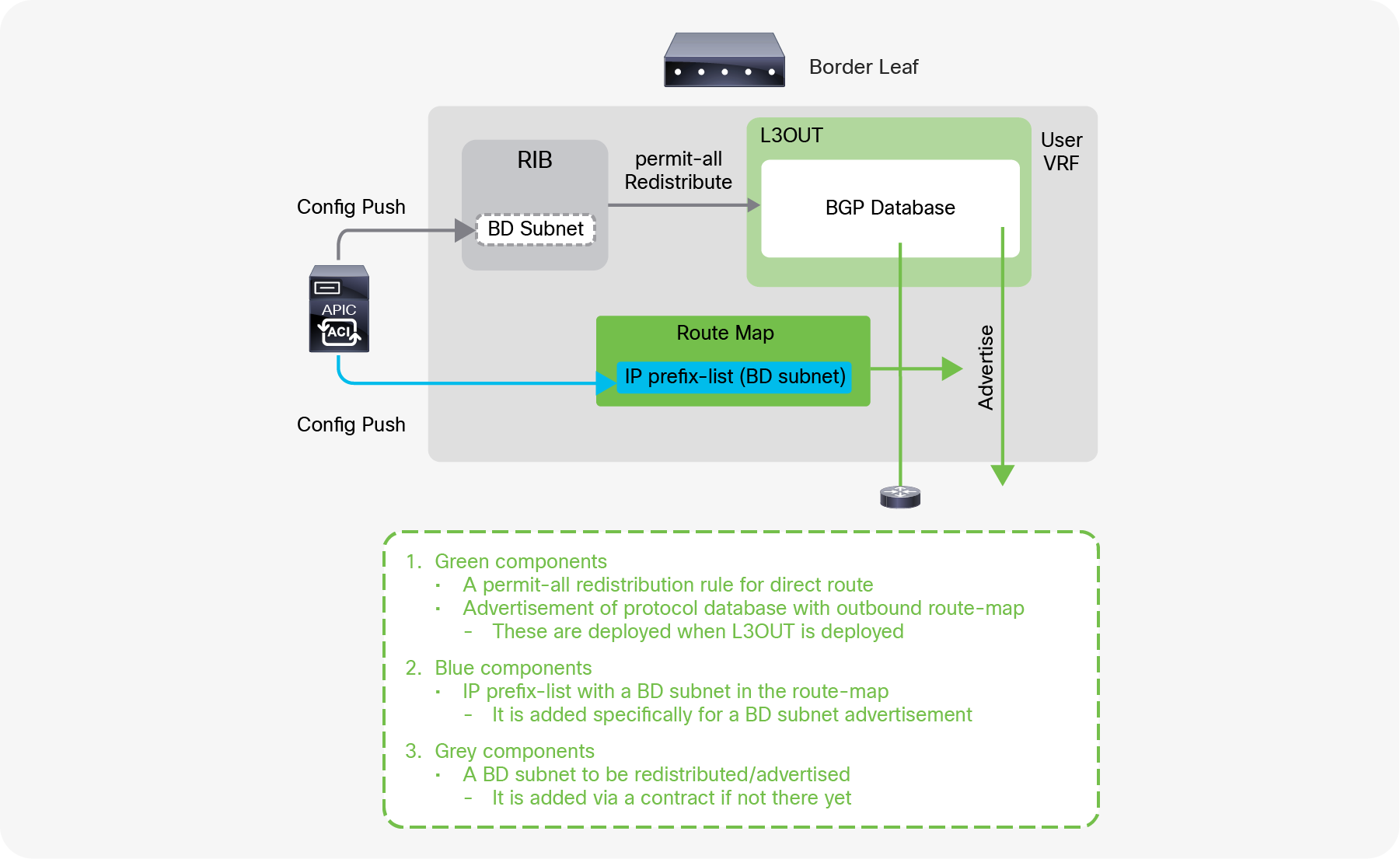
BD subnet advertisement architecture (BGP)
Figure 71 explains what happens under the hood for BD subnet advertisements in BGP. Although most of the programming of the control plane and the data plane of the border leaf is the same as with OSPF/EIGRP, the configuration performed by APIC for BGP in the background needs a slightly different approach due to the use of Infra MP-BGP. All the direct/static routes are redistributed into BGP IPv4 AF first for infra MP-BGP, and then APIC configures which routes to advertise to its BGP peer with an outbound route-map. The blue component is to add IP prefix-list for the BD subnet into the outbound route map (in the case of OSPF/EIGRP, the IP prefix-list was added in the route map for redistribution).
| Note: The name of the route map for direct route redistribution in OSPF/EIGRP is in the form of “exp-ctx-st-<VRF VNID>” and is shared between OSPF and EIGRP on the same border leaf in the same VRF. |
| Leaf1# show ip ospf vrf TK:VRF1 | grep -A 4 Redist Redistributing External Routes from static route-map exp-ctx-st-2916353 <-- “exp-ctx-st-<VRF VNID>” direct route-map exp-ctx-st-2916353 <-- “exp-ctx-st-<VRF VNID>” bgp route-map exp-ctx-proto-2916353 eigrp route-map exp-ctx-proto-2916353 |
The name of the route map for the BGP peer outbound is in the form of “exp-L3Out-<L3Out name>-peer-<VRF VNID>” and is shared with all the BGP peers in the same L3Out.
| Leaf1# show bgp ipv4 unicast neighbors vrf TK:VRF1 | egrep 'BGP nei|Outbound' BGP neighbor is 102.0.0.9, remote AS 65009, ebgp link, Peer index 1 Outbound route-map configured is exp-L3Out-BGP-peer-2916353, handle obtained <-- “exp-L3Out-<L3Out name>-peer<VRF VNID>” |
| Note: There are many components that add an IP prefix-list into a route map on a border leaf. Hence, there is typically more than one IP prefix-list in the route map in ACI fabric. When there is no IP prefix-list in a route map yet, the route-map name may be specified in each protocol (such as for redistribution in OSPF/EIGRP, for peer outbound in BGP) even though the route map itself may not yet exist. |
| Note: A BD subnet is not distributed to other leaf switches via infra MP-BGP even though BGP IPv4/v6 AF has a permit-all redistribution route map. A BD subnet is deployed on leaf switches as a static/direct route pointing to the spine proxy TEP exclusively by APIC based on the user configuration such as deployment of EPGs or a contract on the EPGs for the BD. |
This section provides an overview of L3Out subnet scope options. The details of each scope will be explained in later sections.
L3Out subnet scope options such as “Export Route Control Subnet” or “External Subnets for the External EPG” are located under “Tenant > Networking > External Routed Networks > L3Out > Networks > L3Out EPG > General tab > Subnet”.
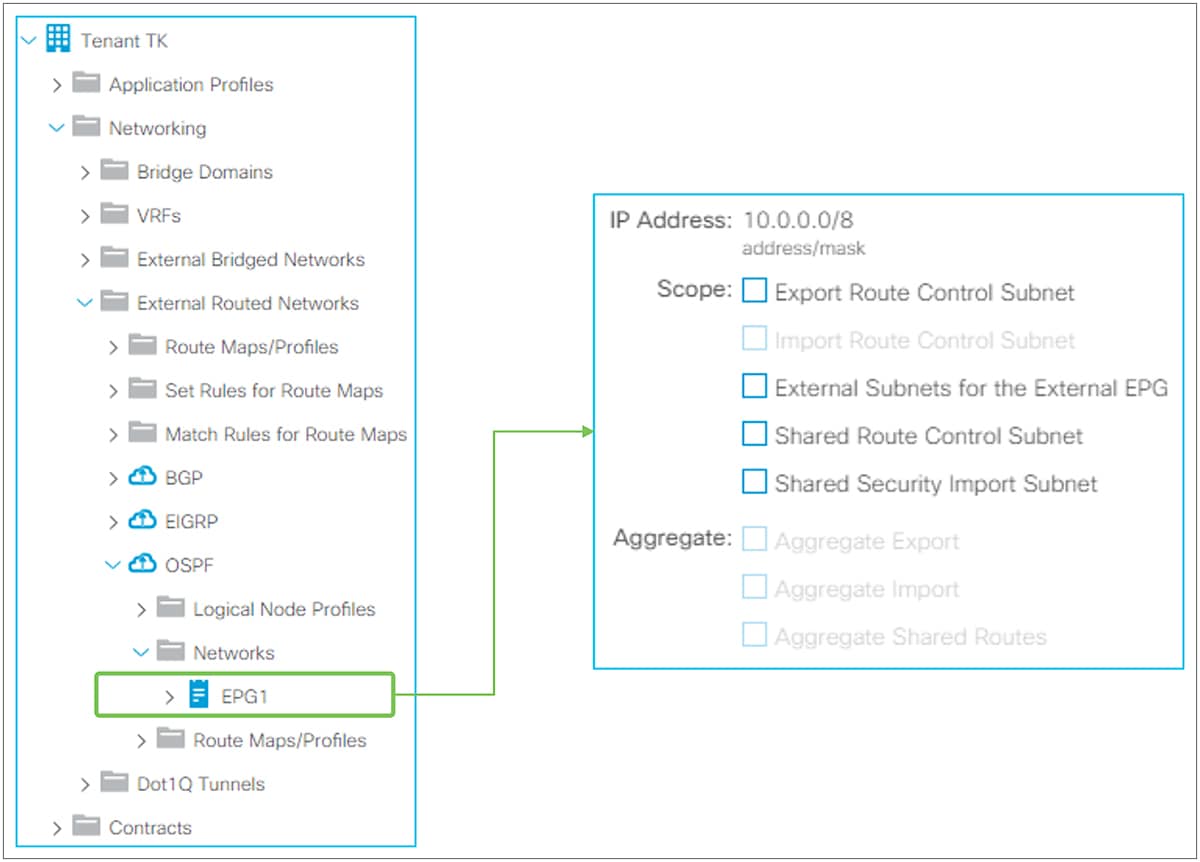
L3Out subnet scope in GUI (APIC Release 3.2)
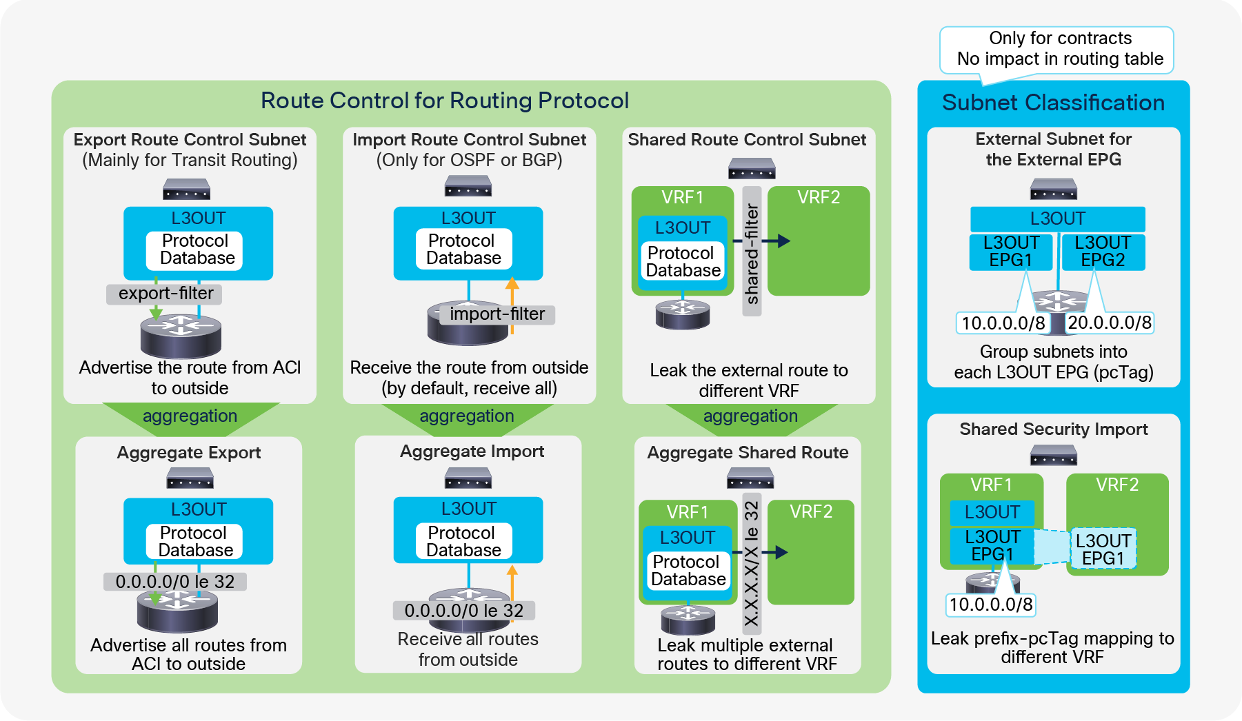
As Figure 73 shows, the scope options along with the aggregate options are grouped into two different groups. One (the green group in Figure 73) is for options to manipulate the routing table and routing protocol via IP prefix-lists and route maps on a border leaf. Another one (the blue group in Figure 73) is for options related to contracts.
Route Control for Routing Protocol
All three scopes here (Export, Import, and Shared) create an IP prefix-list with the specified subnet on a border leaf. Hence, these scopes will affect only a route with an exact match. If you configure a subnet as 10.0.0.0/8 with these scopes, ACI applies the configuration to 10.0.0.0/8 but not to 10.0.0.0/16. In case the requirement is to match multiple subnets with one configuration entry, you need to use the Aggregate option for each scope. Please note that Aggregate option for Export and Import scopes is supported only for 0.0.0.0/0 subnet.
● Export Route Control Subnet
This scope is to advertise (export) a subnet from ACI to the outside via an L3Out. Although this scope is mainly for Transit Routing, it could also be used to advertise a BD subnet, as described in the “ACI BD subnet advertisement” section.
This scope must be configured on an L3Out that is used to advertise the subnet. This scope is not for an L3Out that is learning the subnet. This scope was introduced in APIC Release 1.1(1).
Please refer to the “L3Out Transit Routing” section for details.
● Import Route Control Subnet
This scope is about learning (importing) an external subnet from an L3Out. By default, this scope is disabled, hence it is grayed out in Figure 72, and a border leaf learns any routes from a routing protocol. This scope can be enabled if you need to limit external routes learned via OSPF and BGP. This option is not available for EIGRP.
To use this scope, “Import Route Control Enforcement” needs to be enabled first on a given L3Out (please see the following subsection “Route control enforcement” for details). Once “Import Route Control Enforcement” is enabled on an OSPF L3Out, a border leaf uses a table map with an IP prefix-list for the subnet with “Import Route Control Subnet” so that only those subnets can be used in the routing table even though the routes may be in the OSPF LSDB on a border leaf. When this scope is enabled on a BGP L3Out, a border leaf uses an inbound route-map with an IP prefix-list for the subnet with “Import Route Control Subnet” against all BGP peers in the L3Out. Hence, only the configured routes can be learned in the BGP table in the first place.
This scope is to be configured on an L3Out that is learning the subnet. This scope was introduced in APIC Release 1.1(1).
● Shared Route Control Subnet
This scope is to leak an external subnet to another VRF. ACI uses MP-BGP and route target to leak an external route from one VRF to another. This scope creates an IP prefix-list with the subnet, which is used as a filter to export/import routes with the route target in MP-BGP.
You should configure this scope on an L3Out that is learning the subnet in the original VRF.
Please refer to the “L3Out shared service (VRF route leaking)” section for details.
Route Control for Routing Protocol (Aggregate)
As mentioned above, Export, Import, and Shared Route Control Subnet are an exact match. In case you want to match multiple subnets with one configuration, you can use the Aggregate option for each Route Control Subnet scope.
● Aggregate Export
This option can be used only for 0.0.0.0/0 with “Export Route Control Subnet”. When both “Export Route Control Subnet” and “Aggregate Export” are enabled for 0.0.0.0/0, ACI creates an IP prefix-list with “0.0.0.0/0 le 32”, which matches any subnets. Thus, this option can be used when an L3Out needs to advertise (export) any routes to the outside. This scope was introduced in APIC Release 1.1(1).
When more granular aggregation is required, Route Map/Profile with an explicit IP prefix-list can be used.
● Aggregate Import
This option can be used only for 0.0.0.0/0 with “Import Route Control Subnet”. When both “Import Route Control Subnet” and “Aggregate Import” are enabled for 0.0.0.0/0, ACI creates an IP prefix-list with “0.0.0.0/0 le 32”, which matches any subnets. Hence, this option can be used when an L3Out needs to learn (import) any routes from the outside. However, the same goal can be accomplished by just keeping the default L3Out configuration, which has “Import Route Control Enforcement” disabled. This scope was introduced in APIC Release 1.1(1).
When more granular aggregation is required, Route Map/Profile with an explicit IP prefix-list can be used.
● Aggregate Shared Routes
This option can be used for any subnets with “Shared Route Control Subnet”. When, for example, both “Shared Route Control Subnet” and “Aggregate Shared Routes” are enabled for 10.0.0.0/8, ACI creates an IP prefix-list with “10.0.0.0/8 le 32”, which matches 10.0.0.0/8, 10.1.0.0/16, and so on.
| Note: There are three options to advertise all prefixes: ● 0.0.0.0/0 in Export Route Control Subnet with Aggregate Export ● 0.0.0.0/0 with aggregation option in a prefix list used by a non-default route profile ● 0.0.0.0/0 with aggregation option in a prefix list used by route profile “default-export” However, in the case of OSPF or EIGRP, the first two options advertise only routes from dynamic routing protocols. BD subnets, static routes and L3Out interfacesubnets are not advertised. For the last option - “default-export”, the behavior is different as shown below: ● Prior to ACI 6.0(1) release: “default-export” with a prefix list 0.0.0.0/0 with aggregate advertises all kinds of routes including BD subnets, static routesand L3Out interfaces if there is a L3Out to BD association. ● From ACI 6.0(1) release, “default-export” with a prefix list 0.0.0.0/0 with aggregate advertises all kinds of routes including BD subnets, static routes andL3Out interfaces regardless of a L3Out to BD association. “default-export” is a predefined Route Profile that takes effect without being applied to L3Out EPGs or L3Out subnets, unlike a normal Route Profile.. See the “L3Out Route Profile / Route Map” section for details. |
Subnet classifications for contracts
Two scopes (“External Subnets for the External EPG” and “Shared Security Import”) are used only to apply a contract. No matter what subnets are configured with these two options, it does not affect routing protocol behavior or routing tables.
In ACI, a contract is applied between EPGs. In the L3Out, these two scopes are used to classify a traffic to or from the given L3Out EPG. Internally, an ID called pcTag (a policy-control tag) is used as an identifier for each EPG and L3Out EPG. Please refer to the “L3Out contracts” section for details.
● External Subnets for the External EPG
This scope is used to allow packets with the configured subnet from or to the L3Out with a contract.
It classifies a packet into the configured L3Out EPG based on the subnet so that a contract on the L3Out EPG can be applied to the packet. This scope is a longest prefix match instead of an exact match with an IP prefix-list for other scopes related to the routing protocol control. If 10.0.0.0/16 is configured with “External Subnets for the External EPG” in L3Out EPG A, any packet with an IP address in that subnet, such as 10.0.1.1, will be classified into the L3Out EPG A to apply a contract for the L3Out EPG A. This does not mean the “External Subnets for the External EPG” scope installs a route 10.0.0.0/16 in a routing table. It will create a different internal table to map a subnet to an EPG (pcTag) purely for a contract application. It does not have any effects on routing protocol behavior. Hence, if a routing protocol, or static route, does not have the route for the destination, a packet will not be forwarded even if a packet is classified into the correct L3Out EPG with the appropriate contract thanks to the “External Subnets for the External EPG” scope.
This scope is to be configured on an L3Out that is learning the subnet.
Please refer to the “L3Out contracts” section for details.
● Shared Security Import Subnet
This scope is used to allow packets with the configured subnet when the packets are going across VRFs with an L3Out. A route in the routing table is leaked to another VRF with “Shared Route Control Subnet”, as mentioned above. However, another VRF has yet to know which EPG the leaked route should belong to. The “Shared Security Import Subnet” scope informs another VRF of the L3Out EPG that the leaked route belongs to. Thus, this scope can be used only when the “External Subnets for the External EPG” scope is also used; otherwise, the original VRF doesn’t know which L3Out EPG the subnet belongs to either. The APIC GUI blocks the configuration if “Shared Security Import Subnet” is configured without “External Subnets for the External EPG”. This scope is also a longest prefix match.
Please refer to the “L3Out shared service (VRF route leaking)” section for details.
The Route Control Enforcement option was introduced in APIC Release 1.1(1). This option is located under Tenant > Networking > External Routed Networks > L3Out. Although there are technically two options (Import and Export), Export is always enabled and cannot be disabled. Hence Route Control Enforcement can be considered Import Route Control Enforcement, which is disabled by default. This option must be enabled to use the “Import Route Control Subnet” scope for the L3Out subnet. This option is supported only for OSPF and BGP.
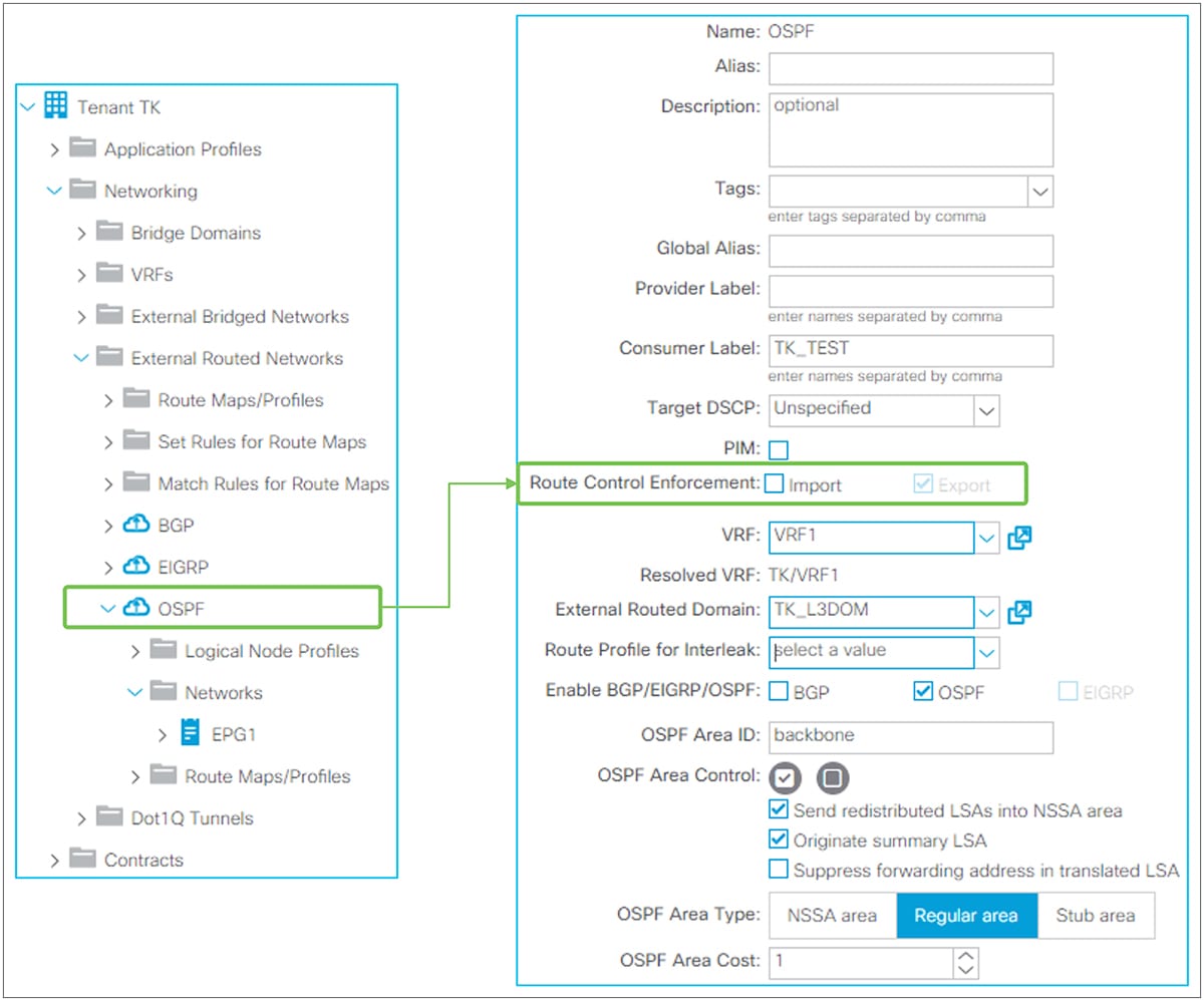
Route Control Enforcement in GUI (APIC Release 3.2)
When the route control import option is not selected (that is, not enabled), the L3Out learns any external routes via routing protocols and those will be installed in a routing table.
When the route control import is enabled for an OSPF L3Out, OSPF still learns any external routes; those will be in OSPF LSDB on a border leaf. However, those routes are not installed in a routing table unless the route subnet is configured with the “Import Route Control Subnet” scope. This is implemented by using the table-map feature from NX-OS OSPF. The subnet with the “Import Route Control Subnet” scope is used in a route map with an IP prefix-list for the table map to allow the subnet to be installed on a routing table.
When the route control import is enabled for a BGP L3Out, BGP stops learning any external routes by using an inbound route map for all BGP peers in the same L3Out. The subnet with the “Import Route Control Subnet” scope is used in the route map with an IP prefix-list to allow the subnet to be learned via BGP.
| Note: When there are multiple L3Outs with OSPF on the same border leaf in the same VRF, the Route Control Enforcement on both L3Outs need to match. Otherwise, a fault F0467 is raised. This is because of the following: One border leaf has only one OSPF process, and each OSPF L3Out on the same border leaf in the same VRF represents different OSPF areas in the same process. However, the table map is applied to the OSPF process level instead of per area. Hence, having OSPF areas (L3Outs) with different Route Control Enforcement configurations on the same border leaf in the same VRF creates a conflict. This also implies the “Import Route Control Subnet” scope configuration on OSPF L3Out A would be applied to the OSPF L3Out B as well if both L3Outs are deployed on the same border leaf in the same VRF. The name of the route map for the OSPF table map is in the form of “exp-ctx-<VRF VNID>-deny-external-tag”. |
The high-level overview of L3Out contracts is covered in step 5 of the “Basic components of L3Out” section. This section goes over the details of the L3Out contract architecture.
A contract in ACI is used to allow traffic between one EPG and another. A packet is typically classified into its appropriate EPG based on the incoming VLAN and incoming interface (there are some exceptions, such as IP-based EPGs for microsegmentation, but that is not covered in this document). In hardware, each EPG is represented by a number called a pcTag (a policy-control tag), and a contract is applied between those numbers.
Example: “EPGA à EPG B” means “pcTag 49150 à pcTag 49151”
The pcTag for each EPG can be checked at “Tenant > Application Profiles > Application EPGs > EPG > Policy tab > General tab > pcTag (sclass)”.
The EPG to classify traffic that enters or leaves the ACI fabric via an L3Out is typically called L3Out EPG or External EPG, located under “Tenant > Networking > External Routed Networks > L3OU > Networks > L3Out EPG”. In the APIC GUI, it is displayed as “External Network Instance Profile” (Figure 75).The L3Out does not rely on the VLAN and interface to classify a packet into the correct L3Out EPG. The classification is based on a source prefix/subnet instead. Hence, the L3Out EPG is occasionally referred as a prefix-based EPG. After a packet is classified into an L3Out EPG and assigned a pcTag based on a subnet, a contract is applied based on the source and destination EPG (pcTag) combination, just as in a normal EPG.
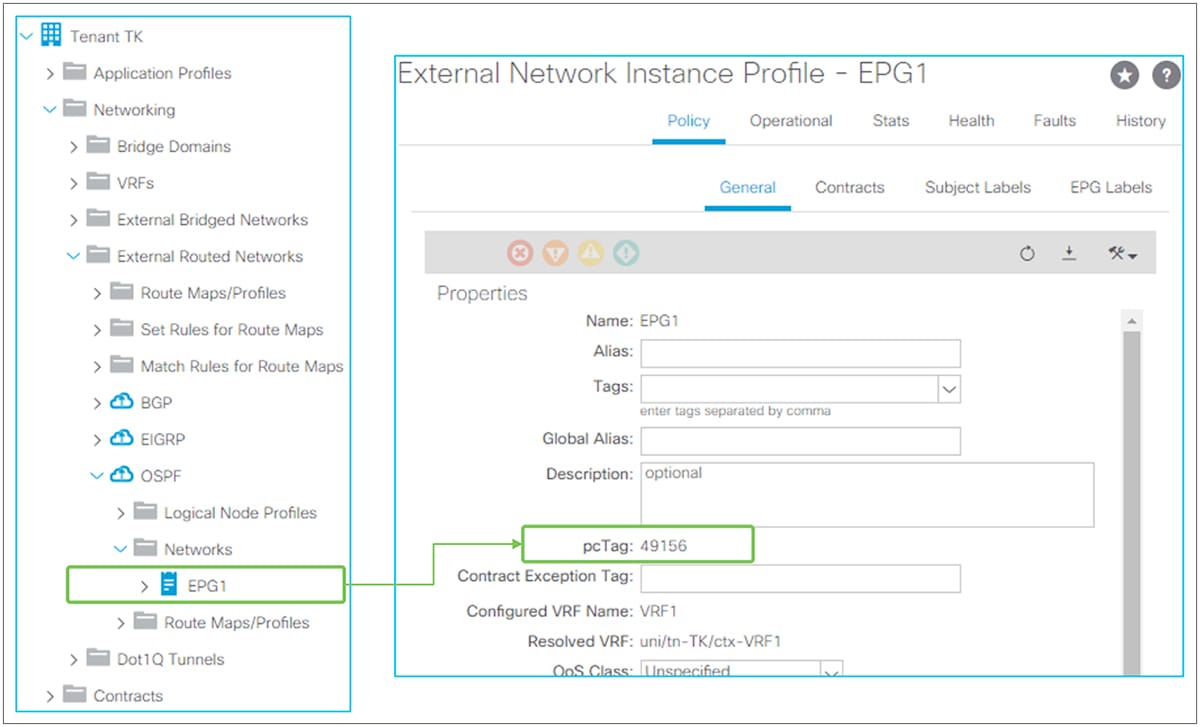
L3Out EPG and pcTag in GUI (APIC Release 3.2)
| Note: A pcTag is unique within a VRF by default. Hence there can be an overlap of pcTags across VRFs, which is not a problem. However, this becomes a problem when doing VRF route leaking (in other words, shared service). In such situations, ACI uses a pcTag called a global pcTag. Note that ACI generates and assigns an appropriate type of pcTag to EPGs without explicit user configurations. A pcTag range lower than 0x4000 (16384) is called global pcTag; it is unique across all VRFs. Please refer to the “L3Out shared service (VRF route leaking)” section for details. |
This section covers details of how a packet is classified into an L3Out EPG, based on subnets.
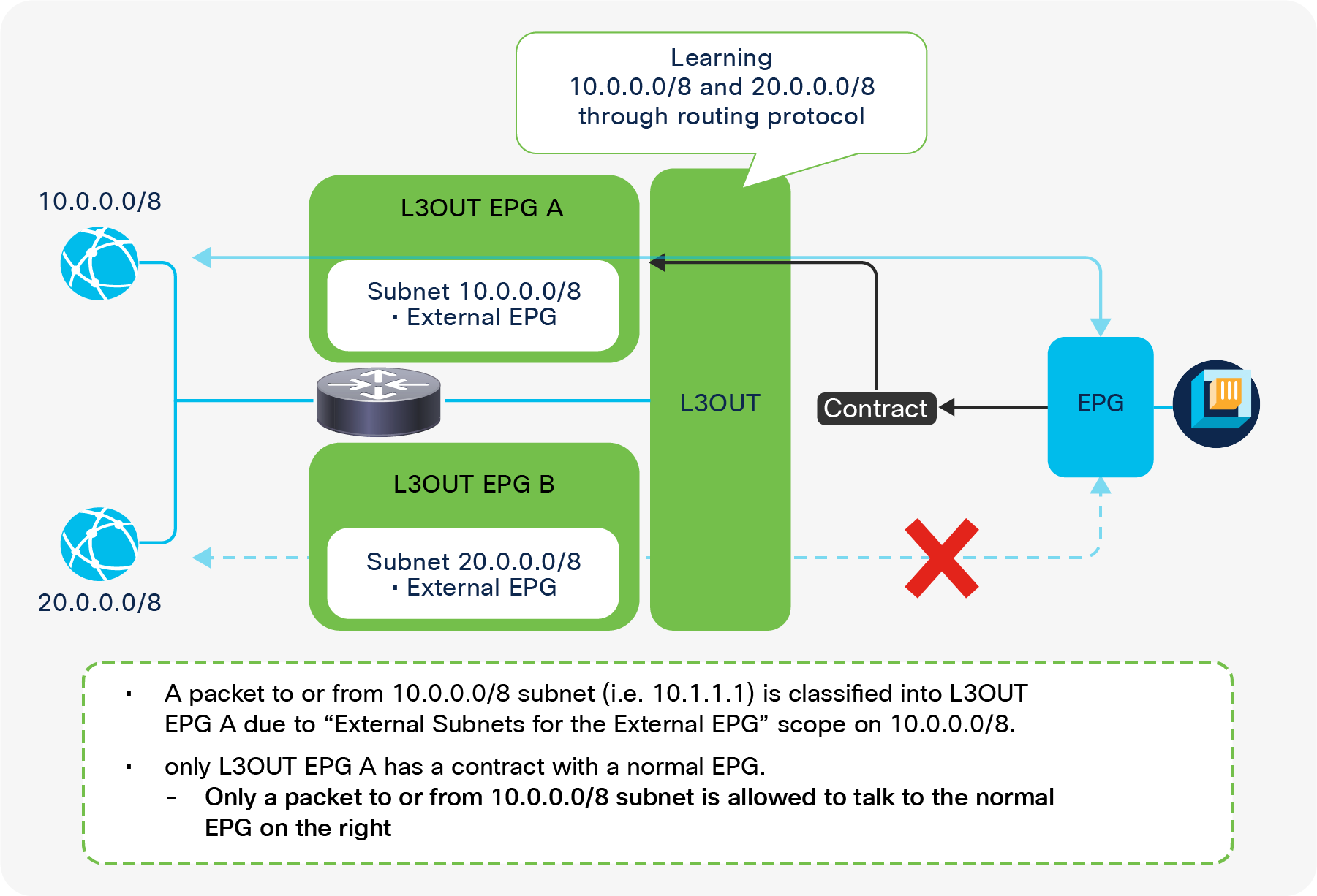
Prefix-based classification for L3Out EPGs
An L3Out is a component to connect to external routing devices instead of an end host. This implies it has many subnets behind it and requires granular subnet classification for contract policies. The L3Out EPG allows you to classify the external traffic based on prefixes. Figure 76 depicts how you configure L3Out EPGs to match different subnets.
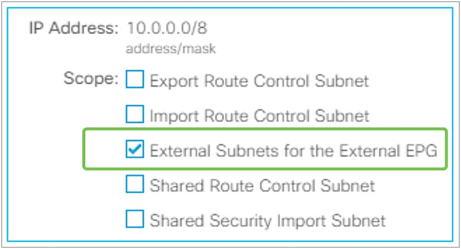
External Subnets for the External EPG
The traffic classification of each L3Out EPG is configured by the “External Subnets for the External EPG” scope on an L3Out subnet under an L3Out EPG (Figure 77)
External Subnets for the External EPG and prefix – pcTag mapping
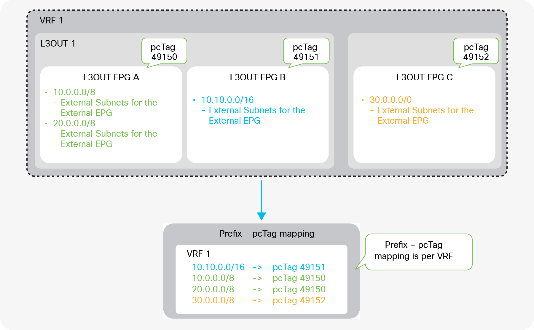
When an L3Out subnet is configured with “External Subnets for the External EPG”, ACI internally creates a table that maps the prefixes and pcTags of the L3Outs. This mapping table is a longest prefix match (LPM) table; a separate mapping table is organized for each VRF. Hence, a subnet with an “External Subnets for the External EPG” scope must be unique across all L3Out EPGs in any L3Outs within the same VRF. If, in Figure 78, the L3Out EPG C had 10.0.0.0/8 with an “External Subnets for the External EPG” scope just like L3Out EPG A, ACI would not be able to tell if 10.0.0.0/8 should be mapped to pcTag 49150 (L3Out EPG A) or to pcTag 49152 (L3Out EPG C). On the other hand, in Figure 78, 10.10.0.0/16 can be configured in L3Out EPG B, since, from an LPM perspective, it is not the same entry as 10.0.0.0/8. A packet with IP 10.10.0.1 will be classified into L3Out EPG B instead of L3Out EPG A.
The following command can be used to check the prefix-pcTag mapping on each leaf switch.
| Leaf1# vsh_lc -c ‘show system internal aclqos prefix’ | egrep ‘Vrf|10.0.0.0’ Vrf-Vni VRF-Id Table-Id Addr Class Shared Remote Complete 2097152 8 0x8 10.0.0.0/8 49200 0 1 No
=== use this command from APIC release 3.2(1) === Leaf1# vsh –c ‘show system internal policy-mgr prefix’ |
● Vrf-Vni: VRF VNID
● Addr: L3Out subnet/prefix with an “External Subnets for the External EPG” scope
● Class: pcTag for L3Out EPG
Caution:
When an endpoint is learned in the ACI fabric, the pcTag of the EPG for the endpoint is also stored in the endpoint table. This means the endpoint IP to the pcTag mapping is also checked when ACI checks prefix to pcTag mapping for L3Outs. This mapping is also based on using a longest prefix match. This implies, with the example of Figure 78, where L3Out EPG A has 10.0.0.0/8 with an “External Subnets for the External EPG” scope, if an external IP such as 10.1.1.1 is learned as a normal endpoint due to a traffic path design mistake or IP spoofing, etc., the packet with IP 10.1.1.1 from or to L3Out 1 will be using a pcTag for the normal EPG of the endpoint 10.1.1.1 instead of L3Out EPG A, because an endpoint is a /32 entry which is preferred to /8 entry in LPM.
To prevent such undesired endpoint learning behavior, please refer to the ACI Fabric Endpoint Learning white paper.
An exception for 0.0.0.0/0 with External Subnets for the External EPG
Users need to be careful regarding the unique behavior that results from using 0.0.0.0/0 as the subnet with an “External Subnets for the External EPG” scope. Although it is not recommended, you can configure 0.0.0.0/0 with “External Subnets for the External EPG” in multiple L3Out EPGs in the same VRF. But you cannot do the same with non-0.0.0.0/0 subnets; for example, multiple L3Out EPGs cannot be configured with the same non-0.0.0.0/0 with “External Subnets for the External EPG” in the same VRF. The reason 0.0.0.0/0 is an exception is because 0.0.0.0/0 with “External Subnets for the External EPG” does not use a pcTag for each L3Out EPG; instead, it always uses the reserved pcTag. While this configuration is allowed, an unintended contract deployment may occur by configuring 0.0.0.0/0 with “External Subnets for the External EPG” in multiple L3Out EPGs within the same VRF. Figure 79 shows this scenario.
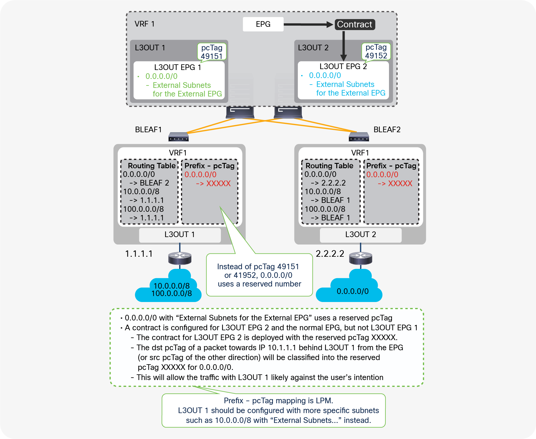
A caveat in 0.0.0.0/0 with "External Subnets for the External EPG"
In Figure 79, 0.0.0.0/0 with an “External Subnets for the External EPG” scope is configured on both L3Out 1 and L3Out 2, where a contract to a normal EPG is only configured with L3Out EGP 2. Hence, you may expect a packet between the normal EPG and the L3Out 1 router should be dropped due to a missing contract. However, any packets between the normal EPG and the L3Out 1 router are allowed, just like packets from the L3Out 2 router. This is because the pcTag classification is not per L3Out, but it relies exclusively on the prefix-pcTag mapping table which is per VRF.
The prefix-pcTag mapping table on the border leaf switches with this configuration will have only one entry with the reserved pcTag for 0.0.0.0/0 instead of 49151 (L3Out EPG1) or 49152 (L3Out EPG2). Then, the contract between the normal EPG and L3Out EPG 2 is deployed with the reserved pcTag for 0.0.0.0/0 and the pcTag for the normal EPG. When a packet is sent out to 10.1.1.1 behind L3Out 1 from the normal EPG, the destination pcTag will be the reserved one (“XXXXX” in Figure 79) based on the prefix-pcTag mapping. Thus, a packet to L3Out EPG 1 is allowed due to a contract rule between L3Out EPG 2 and the normal EPG. If L3Out EPG 1 has 10.0.0.0/8 with an “External Subnets for the External EPG” scope on top of this, the prefix-pcTag mapping table has two entries, one for 0.0.0.0/0 with the reserved pcTag and one for 10.0.0.0/8 with 49151 (L3Out EPG1 pcTag), and the packet is classified into pcTag 49151 due to the LPM rule. The packet is then dropped due to a missing contract.
Therefore, the recommendation is to use 0.0.0.0/0 with an “External Subnets for the External EPG” scope in only one L3Out EPG per VRF, and to use more-specific subnets for other L3Out EPGs.
| Note: This behavior may depend on the Policy Control Enforcement Direction option. If nondefault “Egress” is used, contract may be applied on each border leaf. If the two L3Outs are deployed on different border leaf switches, each border leaf switch has only its own contract rules. This means an inappropriate contract is not applied, at least on each border leaf. However, there are many scenarios where contracts are applied on non–border leaf switches that may have contract rules for both L3Outs. Hence, the recommendations on the usage of 0.0.0.0/0 as the subnet with an “External Subnets for the External EPG” scope remain the same. |
| Note: The reserved pcTag for 0.0.0.0/0 with an “External Subnets for the External EPG” scope depends on the direction of the packets. For the destination pcTag classification (that is, a packet from the ACI fabric to L3Out), ACI always uses pcTag 15 as a fixed value for 0.0.0.0/0. For the source pcTag classification (that is, a packet from L3Out to an endpoint in the ACI fabric), ACI uses a pcTag of the VRF or L3Out BD (an L3Out BD has the same pcTag as its VRF) for 0.0.0.0/0. The reason pcTag 15 is not used for both the source and the destination is to avoid allowing traffic where both the source and destination fall under 0.0.0.0/0 pcTag-prefix mapping. If both source and destination have the same value, the traffic would be assumed as a communication within the same EPG, and the communication would be allowed. |
An exception for a directly connected subnet with 0.0.0.0/0
Prior to covering the details, a general recommendation is to always configure the L3Out interface subnet with the “External Subnets for the External EPG” scope just in case.
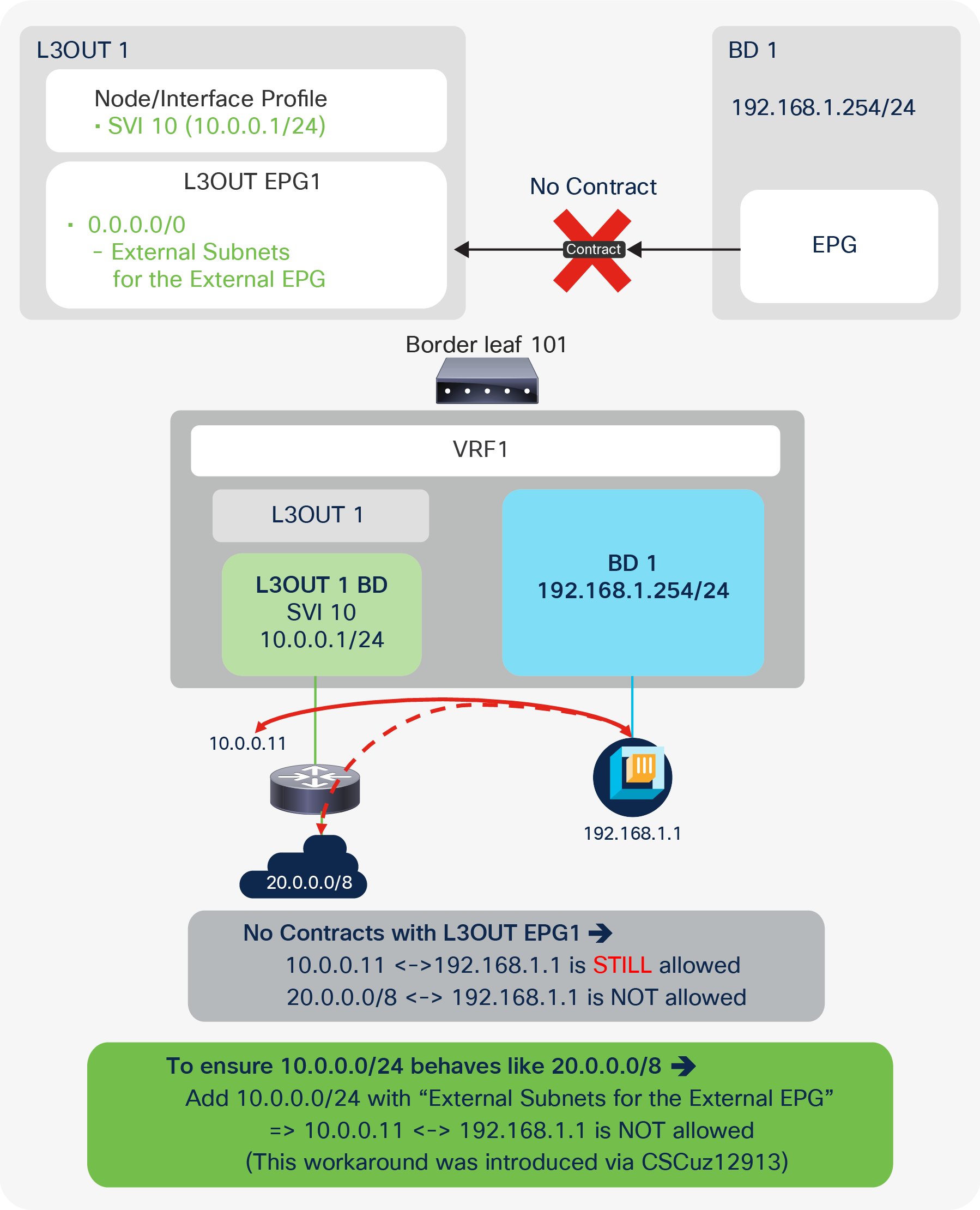
L3Out contract and directly connected subnet (unexpected allow)
As shown in Figure 80, traffic between an IP in an L3Out directly connected subnet (10.0.0.11) and other IPs (for example, 192.168.1.1) may be allowed even without a contract. The other IPs could be normal endpoints (EPs) such as in this example, or IPs in other L3Outs. This is because, by default, directly connected subnets are assigned pcTag 1, which is a special pcTag to bypass a contract. This is to implicitly allow routing protocol communications in a corner case scenario. However, as shown in Figure 80, this may cause a security concern instead. Hence, this behavior is explained in detail via defect ID CSCuz12913, which also introduces a workaround configuration:
CSCuz12913 ACI: a contract is not applied to directly connected subnets on L3OUT
Using the enhancement from CSCuz12913, the workaround “configuring a non-0.0.0.0/0 subnet that covers a directly connected subnet with an ‘External Subnets for the External EPG’ scope” will force even a directly connected subnet to use the pcTag of the L3Out EPG instead of pcTag 1. To ensure that no unintended traffic passes through the ACI fabric, it is highly recommended that you explicitly configure a directly connected subnet with an “External Subnets for the External EPG” scope and utilize the enhancement from CSCuz12913. This enhancement is available only on second-generation leaf switches or later.
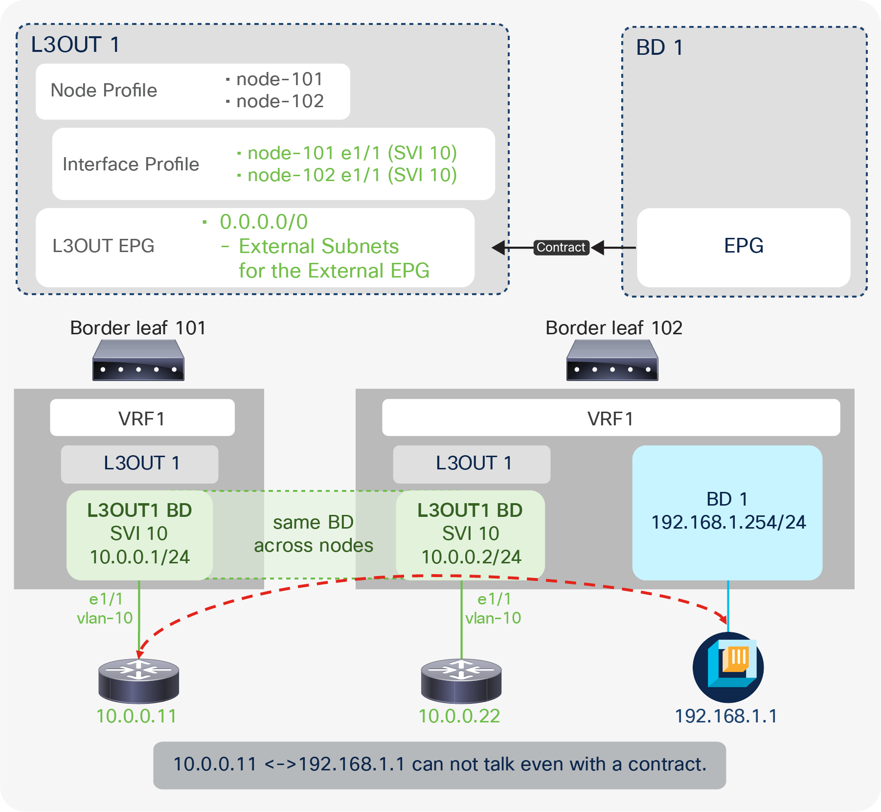
L3Out contract and directly connected subnet (unexpected deny)
Also, this pcTag 1 for directly connected subnets may cause unexpected drops (instead of allows) even with a contract in a corner-case situation (Figure 81). In this corner case, an L3Out BD is spanned across two border leaf switches. Traffic is forwarded from one border leaf (leaf 102) to a directly connected IP 10.0.0.11 on another leaf (leaf 101). The following is a step-by-step explanation on what happens.
1. Leaf 102 has the ARP entry for 10.0.0.11 because it is in the same L2 domain (L3Out BD).
2. Leaf 102 looks up the destination 10.0.0.11. It uses the ARP entry and resolves the next-hop MAC address prior to sending it to leaf 101.
3. At this time, the contract is bypassed on leaf 102 due to pcTag 1 for directly connected subnets.
Even though 10.0.0.11 is technically not directly connected to leaf 102, it is considered connected directly since it has the ARP entry through L3Out BD.
4. The packet reaches leaf 101. The destination MAC is already of the external router (10.0.0.11) instead of the ACI MAC address. A contract has yet to be applied since it was bypassed on a previous node.
5. The lookup is based on the destination MAC address that leaf 101 knows. However, there is no contract for the MAC address in L3Out BD because the L3Out contract is based on a subnet. Hence, it is dropped on leaf 101.
To avoid this issue, the same solution from CSCuz12913 can be applied. When a non-0.0.0.0/0 subnet that covers the direct subnet is configured with an “External Subnet of the External EPG” scope, both leaf 101 and 102 will see the pcTag of the L3Out EPG instead of pcTag 1; therefore, leaf 102 will apply the contract before bridging the traffic on the external BD. The contract is properly applied based on a subnet instead of being bypassed, and the traffic will be forwarded to leaf 101 with the “policy-applied” bit set in its VXLAN header. Leaf 101 will then forward the traffic. Please note that this is only for a directly connected subnet. If the traffic is destined to another subnet behind the external router (10.0.0.11), there will be no such issue. Figure 82 shows one of the typical topology examples for this issue with Multi-Pod.
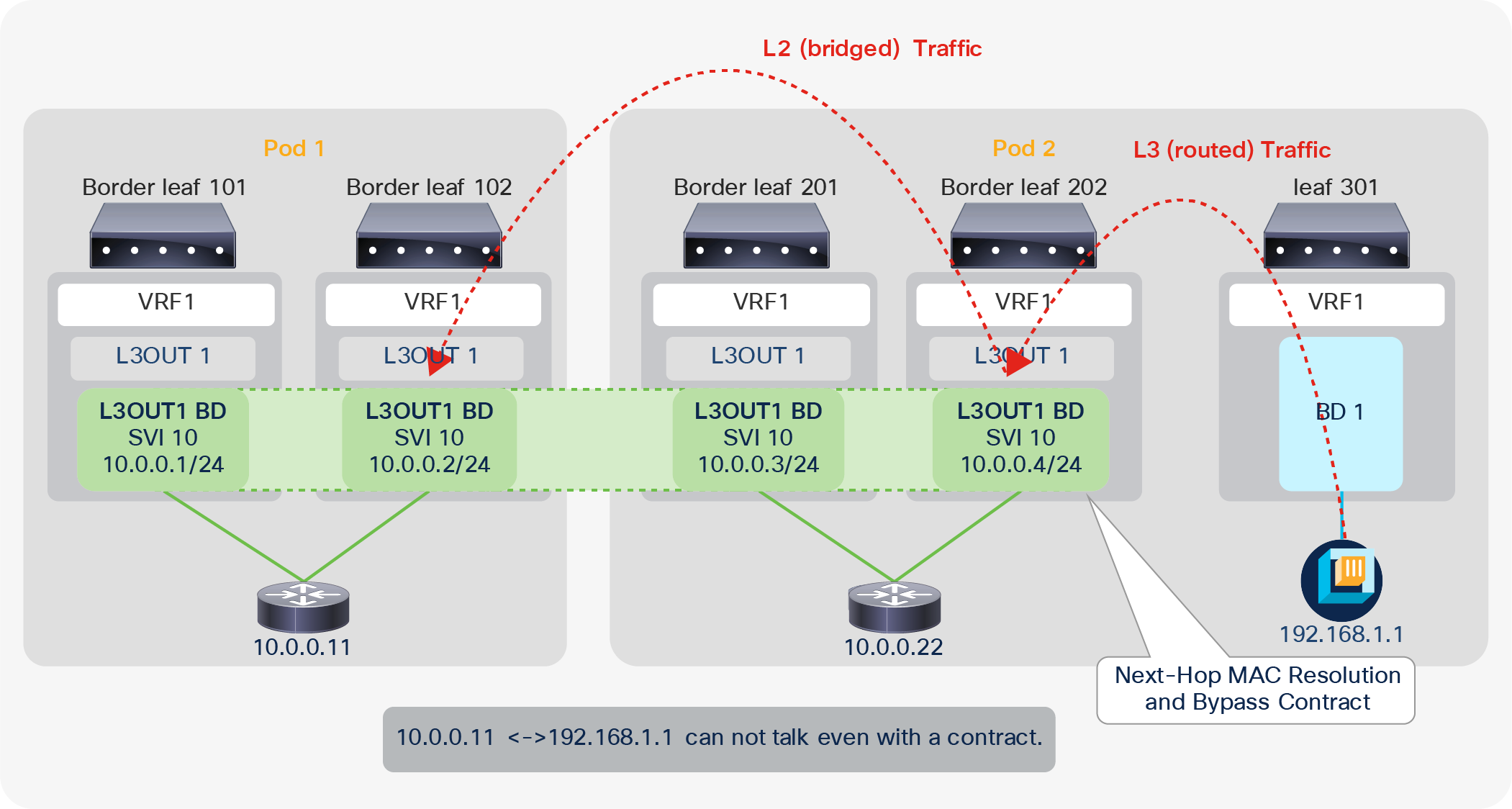
L3Out contract and directly connected subnet (unexpected deny, part 2)
Policy Control Enforcement Direction
The Policy Control Enforcement Direction option was introduced in APIC Release 1.2(1). It is located under “Tenant > Networking > VRFs > VRF”. It can be set as either “Ingress” or “Egress”. The “Egress” option is equivalent to the behavior prior to Release 1.2(1). Hence, to keep behavior consistent across upgrades, if the VRF was created prior to Release 1.2(1) and the ACI fabric is upgraded to 1.2(1) or later, the option is set to “Egress”. From the APIC Release 1.2(1) release the default configuration is “Ingress”.
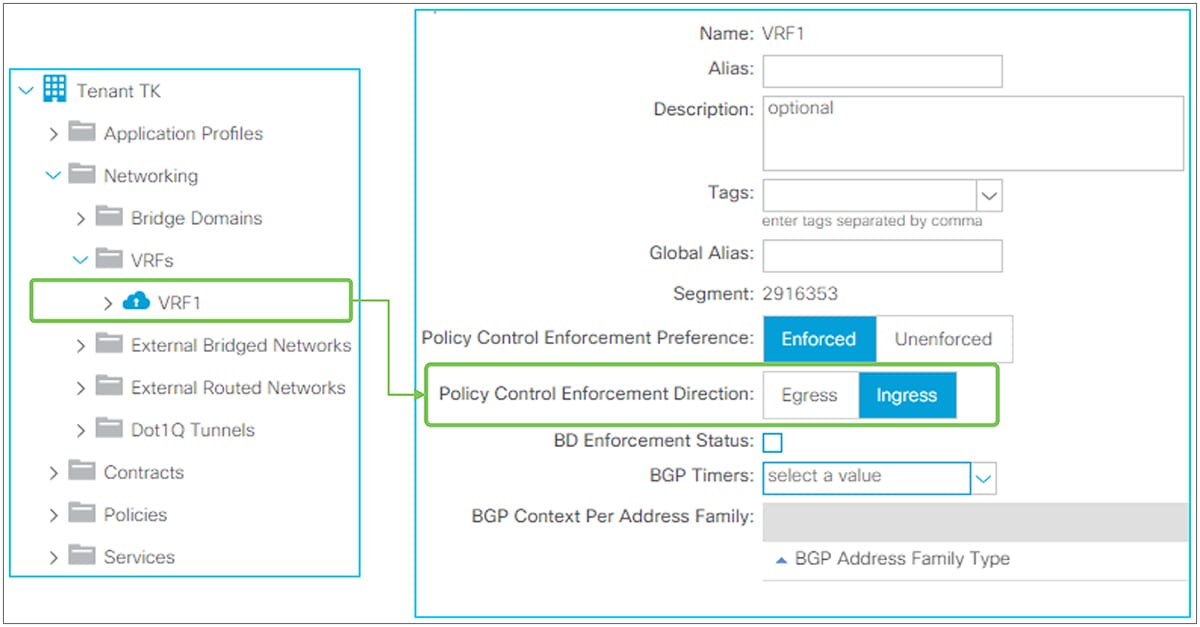
Policy Control Enforcement Direction in GUI (APIC Release 3.2)
Policy Control Enforcement Direction is a feature to save TCAM resources for contracts on border leaf switches. Thus, it affects only traffic to or from the L3Out. There are no behavior changes in EPG-to-EPG traffic based on this option. Typically, users do not need to change the mode of this configuration since the default “Ingress” is the mode for saving TCAM resources.
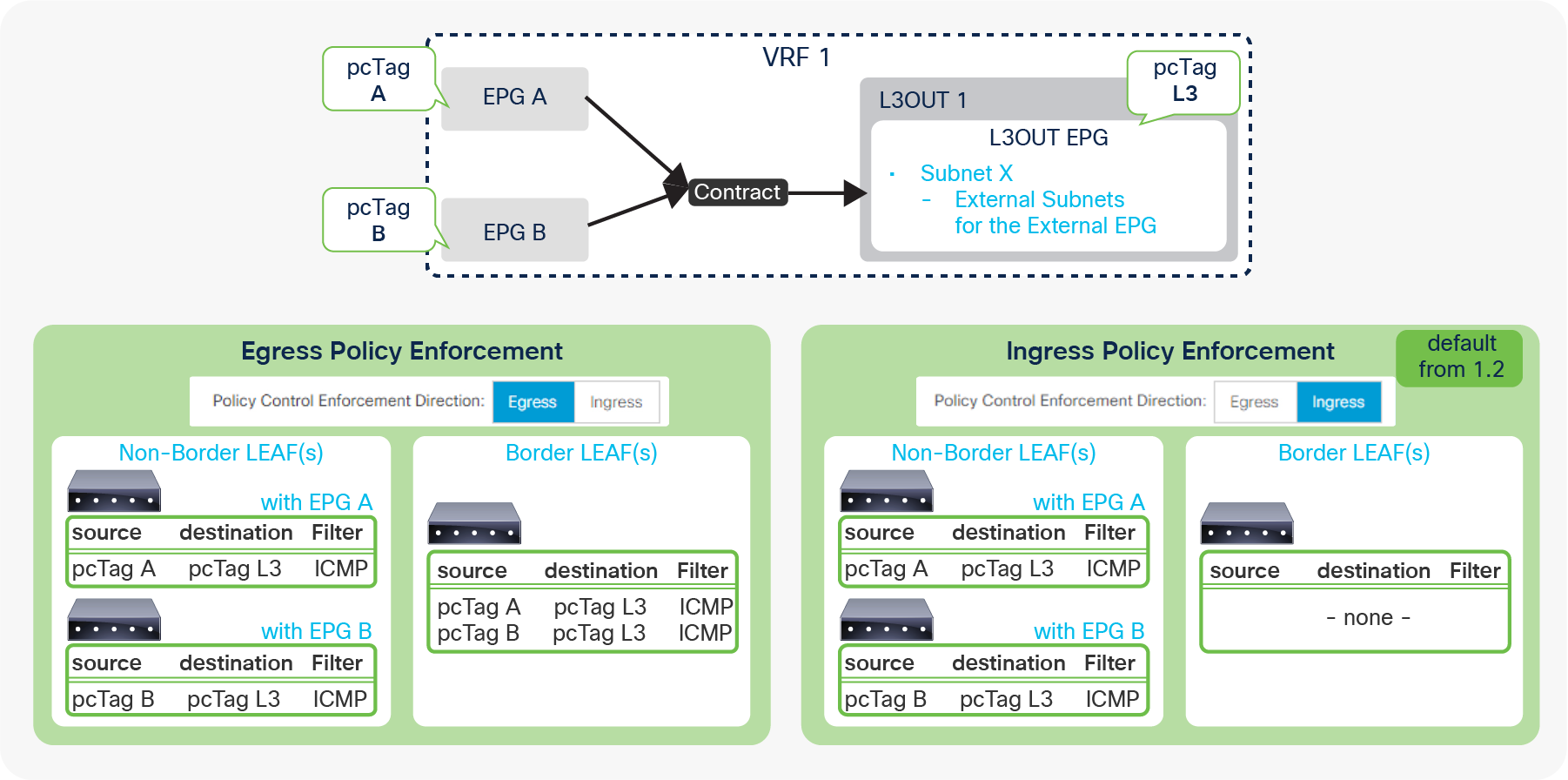
Policy Control Enforcement Direction and contracts
When Policy Control Enforcement Direction is set to “Egress” (see the left bottom in Figure 84), the contract rules for an L3Out are deployed on both border-leaf and non–border-leaf switches. In this situation, when there are many EPGs that need to talk to the L3Out, the TCAM resources for contracts on border leaf switches could be a bottle neck because a border leaf deploys all contracts while contracts on non–border leaf switches are typically distributed to multiple leaf switches. However, when set to “Ingress”, the contract rules are deployed only on non-border leaf switches; hence, this resolves the concern about TCAM resources for contracts on border leaf switches.
In summary, when this feature is set to “Ingress”, a contract for packets from or to L3Out is always applied on a non–border leaf. Figure 85 shows the details on how and where a contract is applied in each scenario.
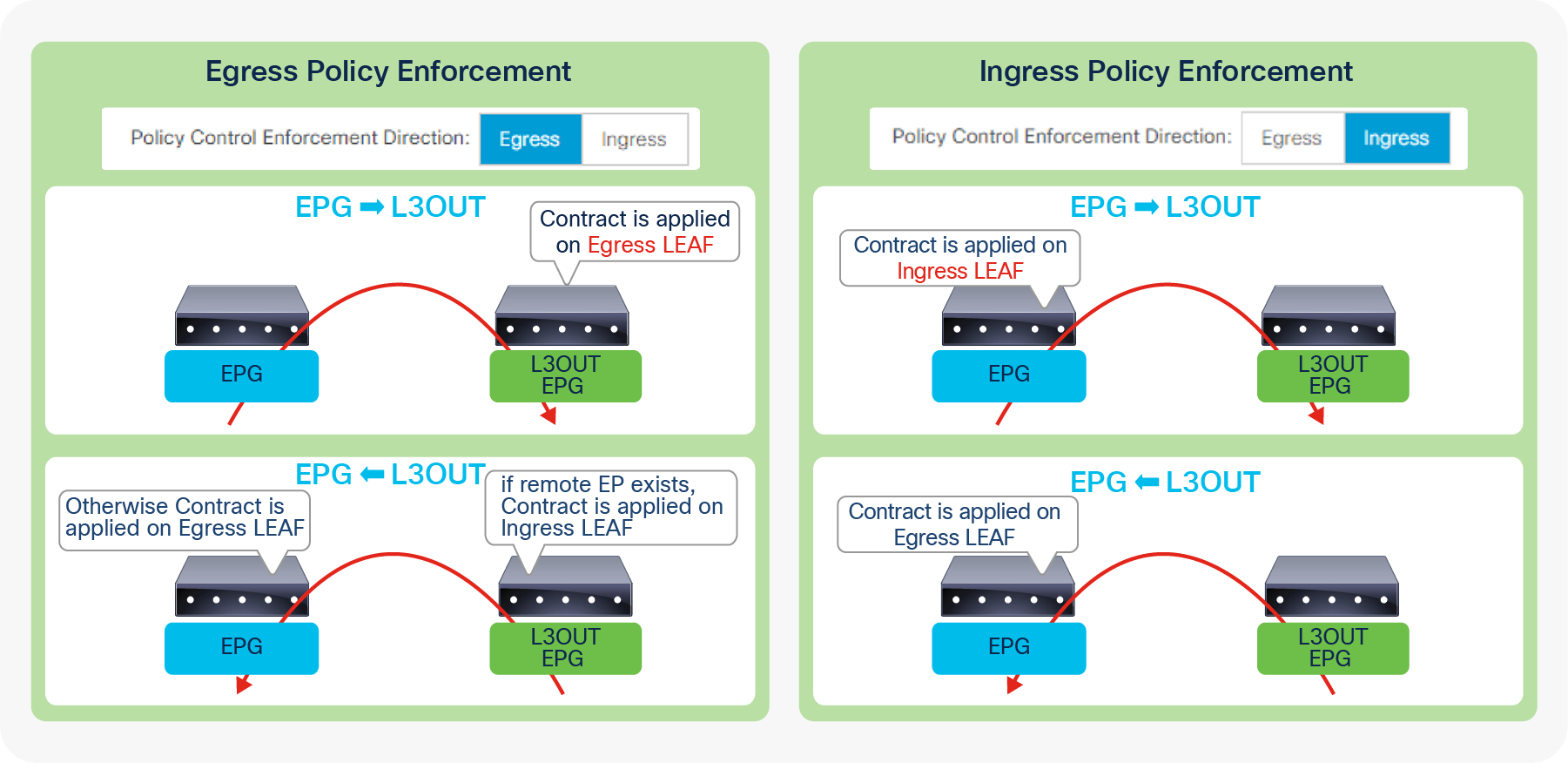
Policy Control Enforcement Direction and packet flow
First, let’s focus on packets from a normal EPG to an L3Out (see the top two diagrams in Figure 85). For this flow, a non–border leaf is an ingress leaf and a border leaf is an egress leaf. With the “Egress” option in this feature, a contract for this flow is always applied on a border leaf (egress leaf). With the “Ingress” option, a contract for the same flow is always applied on a non–border leaf (ingress leaf).
For the traffic flow in the opposite direction (that is, from the L3Out to a regular EPG), since the destination is a normal endpoint, whether a contract is applied on the ingress leaf (in this case, a border leaf) or the egress leaf (here a non–border leaf) depends on the remote endpoint’s learning on the ingress (border) leaf when this feature is set to “Egress”. If the remote endpoint is learned on the ingress leaf, the ingress leaf knows both the source (L3Out) and the destination (EPG) pcTag to apply a contract. Therefore, the ingress leaf can apply the contract; otherwise, the contract is applied on the egress (non–border) leaf. However, with “Ingress” mode, the ingress leaf does not have a contract rule to apply; thus, it is always applied on the egress leaf.
Transit Routing was introduced in APIC Release 1.1(1). This is a feature to allow the ACI fabric to be a transit network by advertising external routes that were learned from one external routing domain to another. Prior to this feature, the ACI fabric was meant to be a pure Stub network. The “Export Route Control Subnet” scope under the L3Out EPG subnet was introduced for this feature. It is located under “Tenant > Networking > External Routed Networks > L3Out > Networks > L3Out EPG > Subnets”.
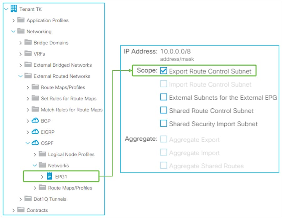
Transit Routing in GUI (APIC Release 3.2)
| Note: The “Import Route Control Subnet” scope under L3Out EPG subnet was also introduced as part of Transit Routing to provide controls not only for external routes that ACI advertises out, but also for the external routes that ACI may learn. However, the “Import Route Control Subnet” scope is not used as often because the default import behavior where ACI learns all external routes suffices in most situations. |
| Note: For supported routing protocol combinations in Transit Routing, please refer to the Supported Transit Combination Matrix in the “Transit Routing” section of the Cisco APIC Layer 3 Configuration Guide. |
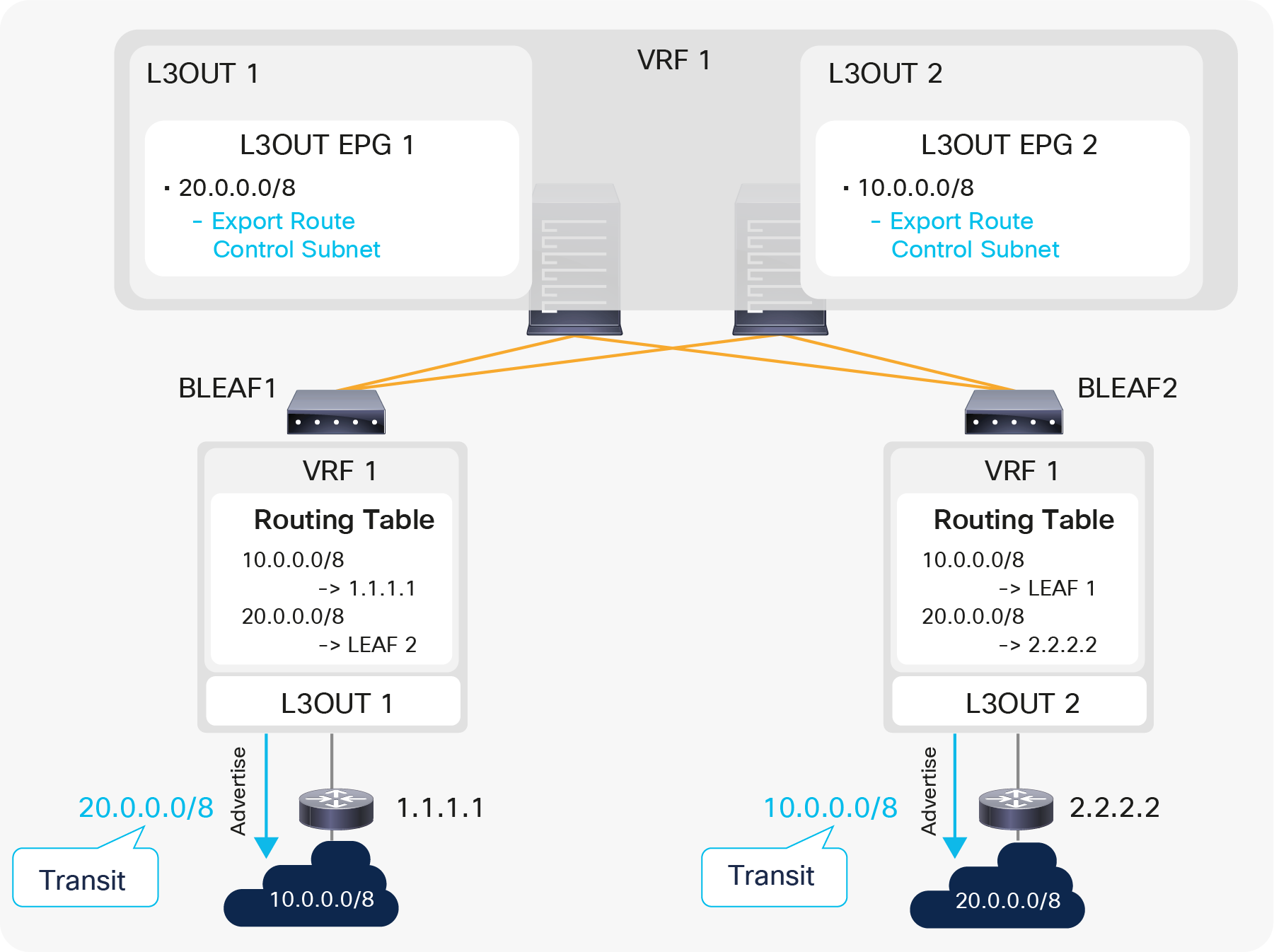
A simple example of a Transit Routing diagram
Figure 87 is a simple example for Transit Routing without any contracts. The purpose of Figure 87 is to illustrate the fact that the “Export Route Control Subnet” scope is used to advertise routes from one L3Out to another. Please keep in mind that the “Export Route Control Subnet” scope is used only on an L3Out that needs to advertise routes and not on an L3Out that is learning routes.
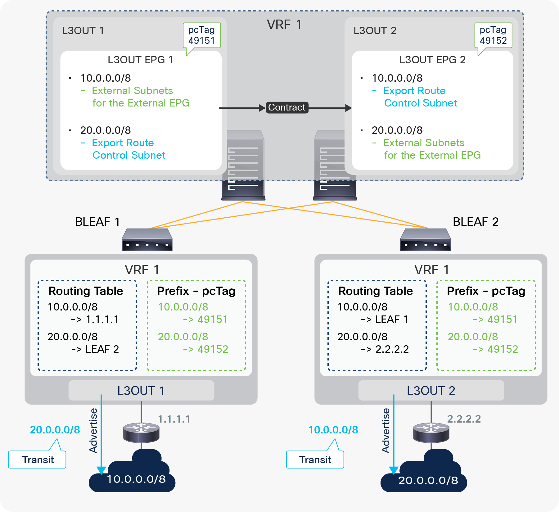
Figure 88 is the same Transit Routing example as shown in Figure 87, with the inclusion of the contract portion for traffic filtering. L3Out 1 and 2 are in the same VRF on two different border-leaf switches. ACI fabric is learning a route 10.0.0.0/8 from L3Out 1 and 20.0.0.0/8 from L3Out 2. The requirement here is that devices in 10.0.0.0/8 and 20.0.0.0/8 can communicate with each other through ACI L3Out 1 and 2. There are two configurations to accomplish this: routing and contract, the same as in any other L3Out scenario. To complete the routing part for Transit Routing, ACI uses the “Export Route Control Subnet” scope. Here, L3Out 1 needs to advertise 20.0.0.0/8 to its peer. Hence, 20.0.0.0/8 with an “Export Route Control Subnet” scope is configured under L3Out 1. If 20.0.0.0/8 is already available on border leaf 1 because of infra MP-BGP, it is redistributed into the L3Out 1 routing protocol and advertised via L3Out 1. A common mistake is to configure 20.0.0.0/8 with an “Export Route Control Subnet” scope on L3Out 2, which is learning 20.0.0.0/8, instead of on L3Out 1, where you want the route to be advertised from. The same applies to 10.0.0.0/8 with an “Export Route Control Subnet” scope on L3Out 2. It is configured on L3Out 2, and L3Out 2 starts advertising 10.0.0.0/8 to the outside if the route is available on border leaf 2. The contract configuration is not specific to Transit Routing.
The same principle as in EPG-to-L3Out communication applies here. Users configure L3Out 1 and 2 with the “External Subnets for the External EPG” scope for the respective subnets to map them into each L3Out EPG (pcTag). A contract is applied between those two L3Out EPGs (pcTags).
Caution:
As mentioned in step 4 in the “Basic components of L3Out” section, configuring an “Export Route Control Subnet” scope and an “External Subnets for the External EPG” scope on the same subnet in the same L3Out is a mis-configuration except for OSPF Inter-Area route summarization, and can potentially create a routing loop. An “External Subnets for the External EPG” scope implies that the subnet belongs to a routing domain behind this L3Out. Yet ACI is trying to advertise (export) the subnet back to the L3Out. Even though these advertisements are normally blocked implicitly by the routing-loop-prevention mechanism in each routing protocol, there can be a situation where the advertisement may occur. Hence, this configuration should be avoided.
When exporting all subnets using an “Export Route Control Subnet” scope and an “Aggregate Export” option, the exporting subnet will, unavoidably, include its own subnet. Therefore, please perform such configurations in general with decent care, as you would for any other routing devices with redistribution.
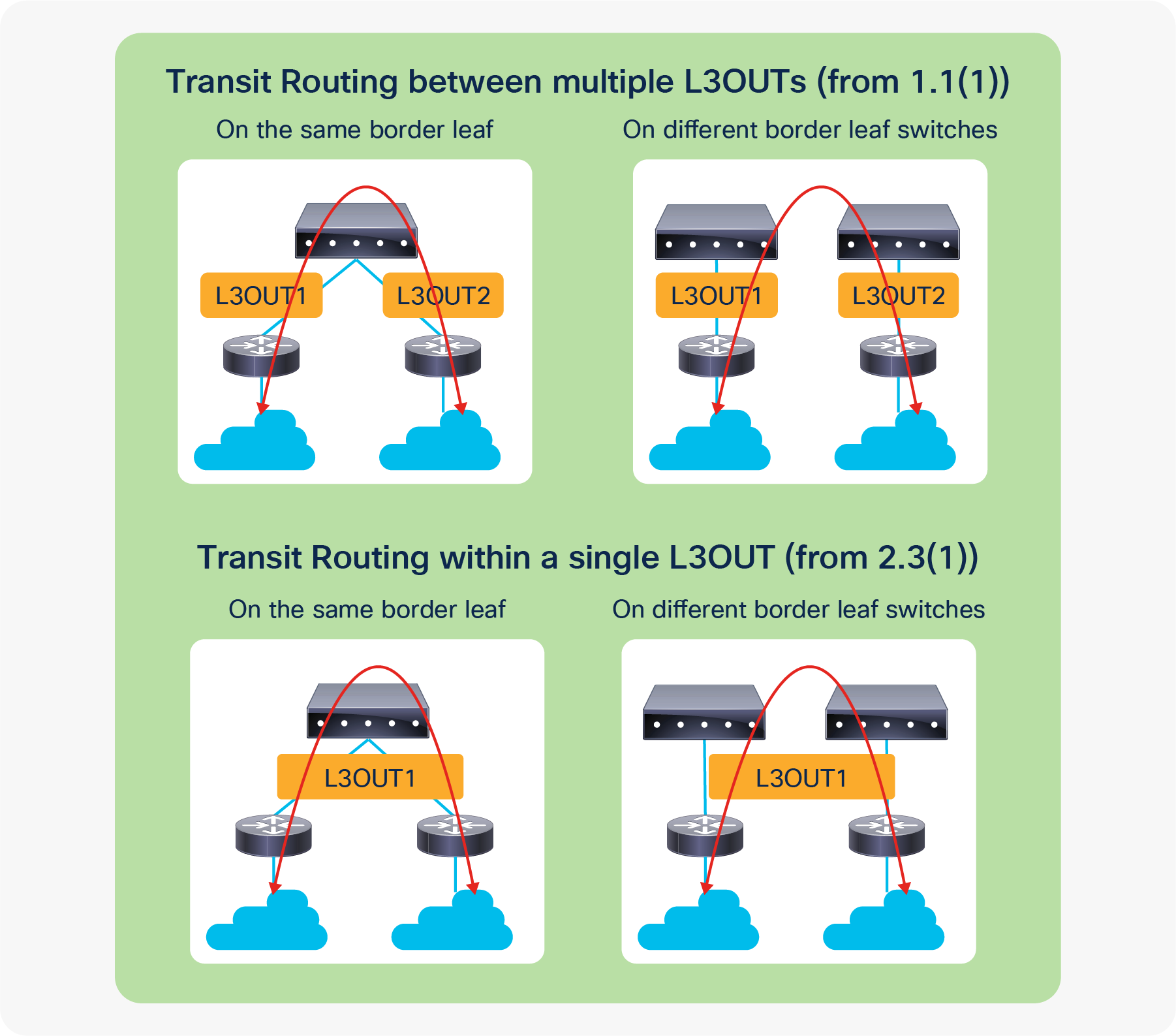
Figure 89 illustrates four main topologies of Transit Routing. The top two with multiple L3Outs are the original Transit Routing topologies. Transit Routing within a single L3Out between multiple routing devices (the bottom two) were introduced in APIC Release 2.3(1) with a limitation in contracts for 0.0.0.0/0 with an “External Subnets for the External EPG” scope. Please refer to Guidelines for Transit Routing in the “Transit Routing” section of the Cisco APIC Layer 3 Network Configuration guide or CSCuy16355 for the limitation with 0.0.0.0/0.
| Note: When Transit Routing is performed on the same border leaf across two OSPF L3Outs, one of them needs to be OSPF Area 0 because there will be a route exchange between the OSPF areas without going through infra MP-BGP. |
VRF tag was introduced as a mechanism to avoid a potential routing loop in conjunction with Transit Routing. This feature utilizes OSPF or EIGRP route tagging. Hence, this is mainly for those two protocols instead of BGP.
In ACI, every VRF has its own VRF tag, which by default is the same for all VRFs; it is 4294967295. ACI sets the VRF tag in the subnets that ACI advertises out via L3Outs. This includes both BD subnets and Transit Routes. When performing Transit Routing, OSPF or EIGRP on a border leaf use redistribution (or the OSPF area filter) to get external routes from other L3Outs, and while doing so, ACI sets the VRF tag as a route tag to the redistributed routes. When ACI sees an external route with its own VRF tag, it will not use the route in its routing table, to prevent a potential loop.
| Note: This behavior (not to use such routes) is implemented with the table-map feature from NX-OS, which is also used for the “Import Route Control Subnet” scope for OSPF and EIGRP. Hence, the VRF tag and “Import Route Control Subnet” scope share the same route map for the table map. |
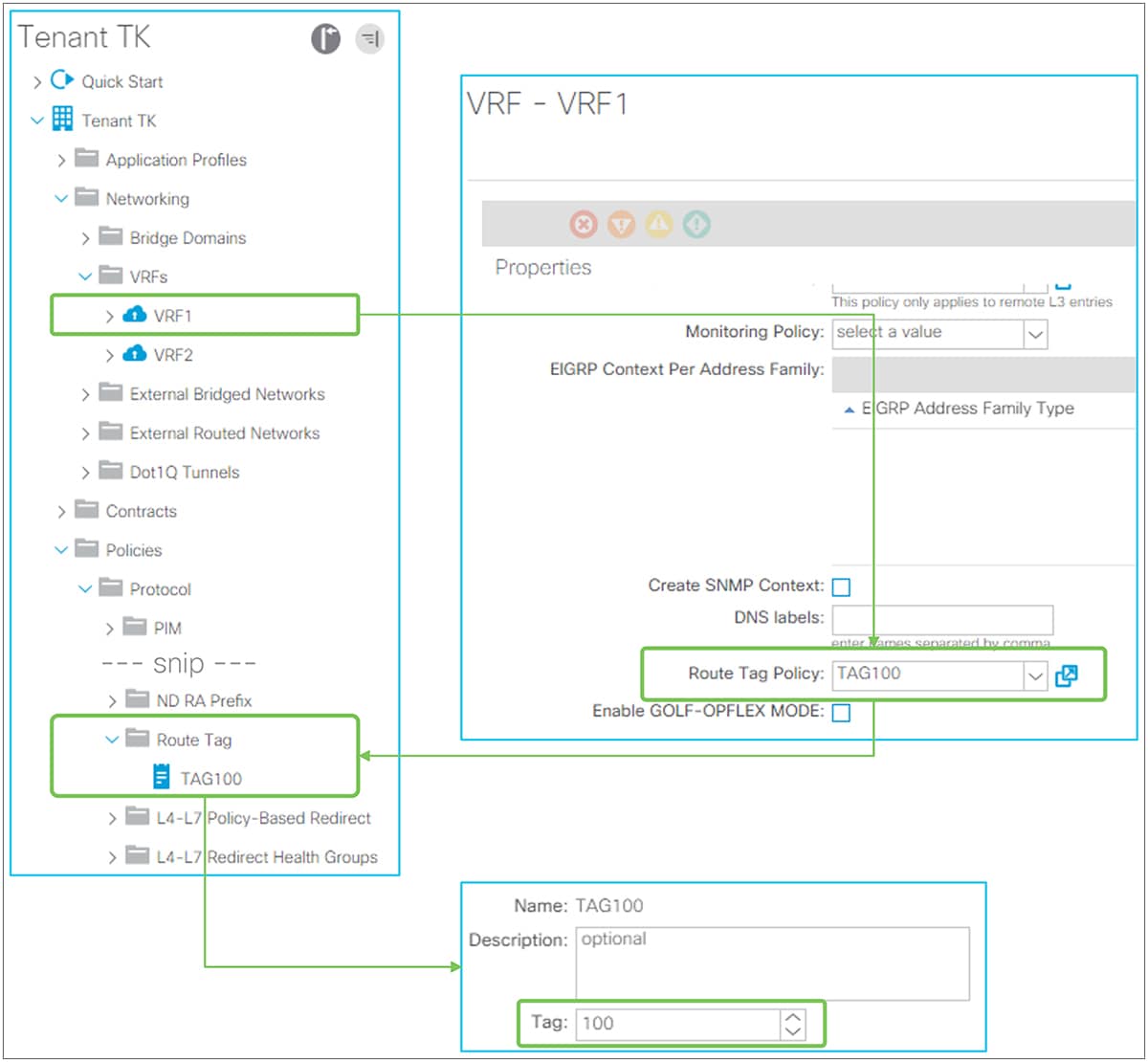
VRF tag in GUI (APIC Release 3.2)
Figure 90 shows how to change the VRF tag for VRF 1. The Route Tag policy is located under “Tenant > Policies > Protocol > Route Tag”. This policy is configured on each VRF that needs to change the VRF tag from a default value. In this example, the VRF tag of VRF1 was changed to 100. If the transit routes are expected to be learned in ACI again from another VRF, then the VRF tag needs to be changed from the default value. Otherwise, the route will not show up in the routing table because all VRFs use the same default VRF tag by default. The example in Figure 91 shows this issue.
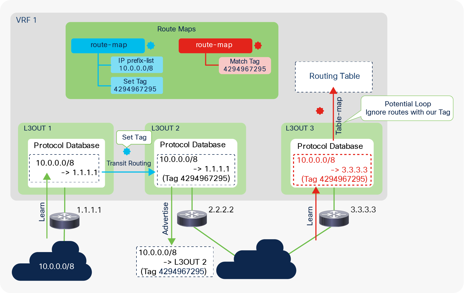
Using VRF tags in Transit Routing to prevent loops
Figure 91 is an example to show how ACI uses VRF tags to prevent loops. In this example, Transit Routing is configured on L3Out 2 for the route 10.0.0.0/8 that is learned from L3Out 1. ACI sets a VRF tag to 10.0.0.0/8 when L3Out 2 gets the route from L3Out 1. This tag is carried through external routers because it is a standard route tag. When the route is advertised back to ACI for some reason, ACI knows this could be a potential loop due to the route tag. Thanks to the table map on OSPF or EIGRP, this potential loop route does not show up in the routing table. Please see the next subsection, “Internal route-map for Transit Routing,” for details on how Transit Routing is implemented (L3Out 1 to L3Out 2 in Figure 91).
| Note: There are other route tags, on top of 4294967295, that ACI uses internally for various reasons. The following ranges show such route tags. It is recommended to avoid using these manually in your network to prevent conflicts of usage. 4294966001 - 4294966512 4294967287 - 4294967295 |
Internal route-map for Transit Routing
This subsection goes over the details of how a border leaf implements the Transit Routing capability when an “Export Route Control Subnet” scope is configured. ACI utilizes standard routing protocol mechanisms, such as redistribution with route maps. Although users typically don’t need this level of understanding to operate an ACI fabric, it helps to understand the limitations of ACI L3Out and Transit Routing instead of having to memorize them as a list of limitations.
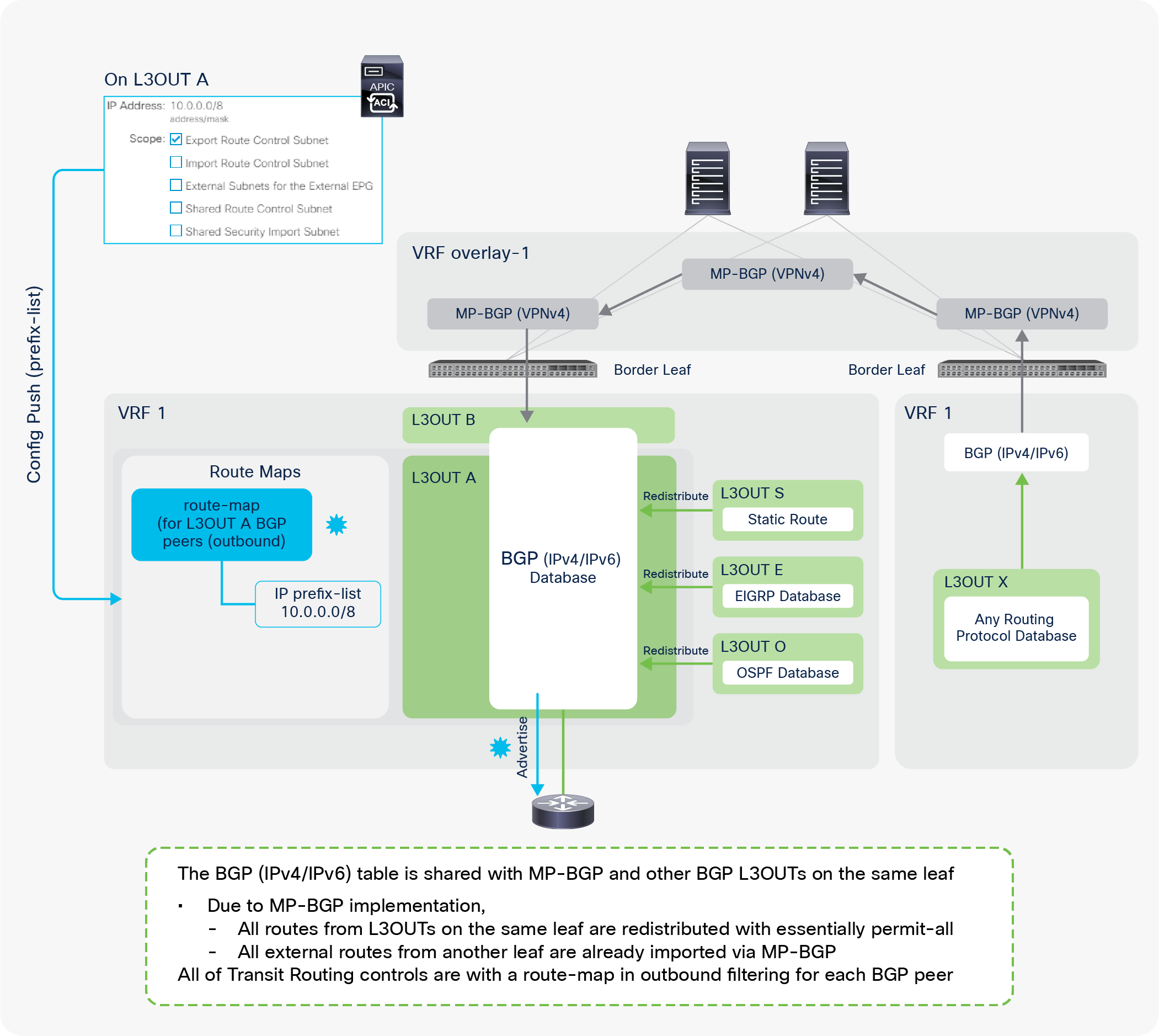
Route-map implementation for Transit Routing with BGP
Figure 92 illustrates all the combinations of L3Outs related to Transit Routing. The focus is advertising routes via BGP L3Out A. It does not mean that all of the other L3Outs have to be deployed at the same time.
The implementation of BGP L3Outs is slightly different compared with that of other L3Outs, such as OSPF and EIGRP, because BGP in the user VRFs is utilized for infra MP-BGP as well as for user L3Outs. Due to the infra MP-BGP implementation, the BGP IPv4/IPv6 database in a user VRF has all of the external routes from other L3Outs on the same border leaf and other border leaf switches without any Transit Routing configurations. Hence, Transit Routing control with the BGP L3Out is performed via an outbound route-map applied to BGP peer neighbor sessions on the border leaf. By default, ACI creates one outbound route-map per BGP L3Out, which is applied to all BGP peers on the same L3Out. This can be changed with the new feature to configure a BGP route-map per peer, which was introduced in APIC Release 4.2(1).
| Note: The outbound route-map for BGP is shared with BD subnet advertisement. It is important to ensure that both Transit Routing for BGP and BD subnet advertisement are configured with the correct subnets to prevent unintended advertisement. Please refer to the “BD subnet advertisement” section for details. |
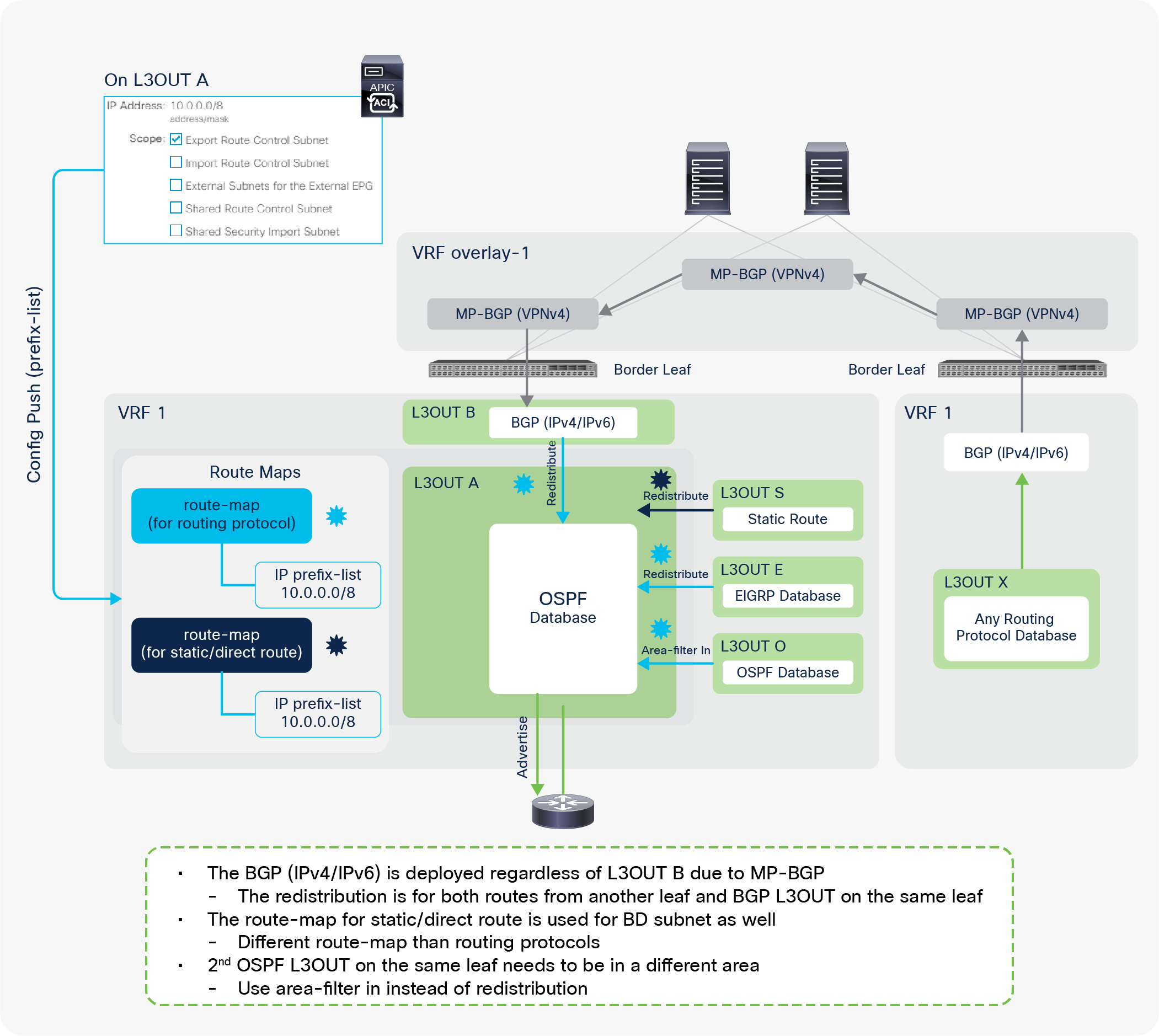
Route-map implementation for Transit Routing with OSPF
Figure 93 illustrates all the combinations of L3Outs related to the Transit Routing. The focus is advertising routes via OSPF L3Out A. It does not mean that all of the other L3Outs have to be deployed at the same time.
The OSPF L3Out implementation for Transit Routing is mainly relying on redistribution. In Figure 93, the external routes from another border leaf should be available on the BGP IPv4/IPv6 table because of infra MP-BGP. The same BGP table is used by the BGP L3Out B as well. Those routes in the BGP table can be used in the routing table but not yet in the OSPF database (LSDB: Link State Data Base). ACI redistributes those routes from BGP to OSPF with an “Export Route Control Subnet” scope so that OSPF can advertise them to the outside for Transit Routing. For other L3Outs such as EIGRP or static route on the same border leaf, ACI also uses redistribution. However, if you had another OSPF L3Out on the same border leaf, the redistribution would not be an option, because it is the same routing protocol. In this case, ACI uses an area-filter with an “in” direction, because each OSPF L3Out on the same border leaf must belong to a different OSPF area.
| Note: In OSPF and EIGRP, ACI internally creates two route maps: one is for routing protocols, the other is for static or direct routes. An “Export Route Control Subnet” scope deploys the same IP prefix-list entry on both route maps. The route map for a static or direct route is shared with BD subnet advertisement because BD subnets are also static and direct routes. It is important to check that both Transit Routing and BD subnet advertisement are configured with the correct subnets, to ensure that only the intended subnets are advertised. Please refer to the “BD subnet advertisement” section for details. Also, both route maps are shared with all OSPF and EIGRP L3Outs in the same VRF on the same border leaf. There is an enhancement request filed to address this shared route-map between OSPF and EIGRP. CSCuy63998 ACI: Export Subnet under EIGRP is applied to OSPF on the same node |
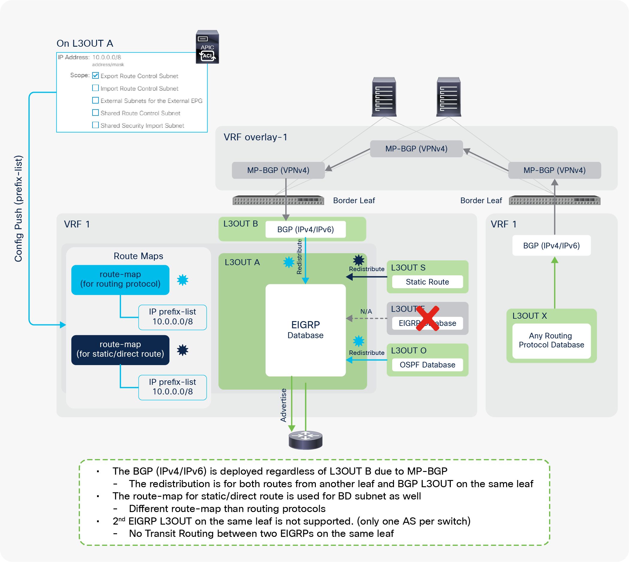
Route-map implementation for Transit Routing with EIGRP
Figure 94 illustrates all of the combinations of L3Outs related to Transit Routing. The focus is advertising routes via EIGRP L3Out A. It does not mean that all of the other L3Outs have to be deployed at the same time.
The EIGRP L3Out implementation for Transit Routing is almost the same as for OSPF. The only difference is that Transit Routing between the same L3Outs using the same protocol on the same border leaf is not supported for EIGRP. This is because the second EIGRP L3Out cannot be configured on the same border leaf, because the EIGRP AS number is per L3Out and there cannot be two EIGRP ASs on the same switch node. Other details, such as route maps that are internally created, are the same as for the OSPF L3Out implementation.
L3Out Route Profile / Route Map
Route Profile / Route Map basics
ACI uses route maps internally for various purposes, such as infra MP-BGP, BD subnet advertisement to the outside, and Transit Routing, as mentioned in the previous sections. ACI provides users with the ability to add user-defined matching or set rules for those internal route maps. This is performed by using Route Profiles, which is sometimes referred to as Route Control Profiles or Route Maps. The following are examples of use cases for this feature:
● A route map to redistribute (export) BD subnets to the outside via L3Outs
● A route map to redistribute (export) external routes from one L3Out to another (Transit Routing)
● A route map to limit learning (importing) external routes from the outside via L3Outs
● A route map to redistribute (interleak) external routes from L3Outs to BGP for infra MP-BGP, etc.
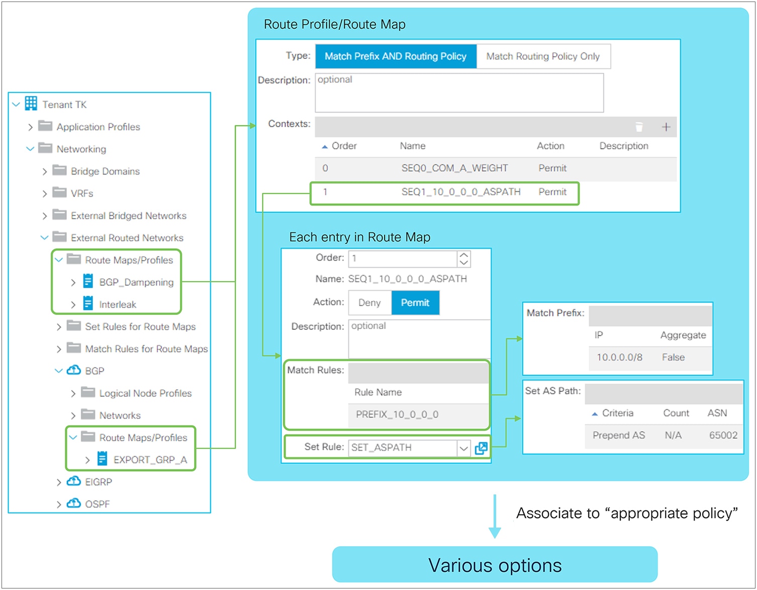
Route Profile Structure in GUI (APIC Release 3.2)
As Figure 95 shows, there are two places to configure Route Profiles. One is at the tenant level, located under “Tenant > External Routed Networks > Route Maps/Profiles”, which was introduced in APIC Release 1.2(2). Another is at the L3Out level, located under “Tenant > External Routed Networks > {L3Out} > Route Maps/Profiles”. Both use Match and/or Set Rules from the tenant level, which is located under “Tenant > External Routed Networks > Set Rules (or Match Rules) for Route Maps”. The difference is the following:
● Tenant-level Route Profile: for interleak (redistribution from OSPF or EIGRP to the infra MP-BGP) and BGP Route Dampening
● L3Out-level Route Profile: for anything else
The components in each Route Profile represent the components in a route map on a normal router, as Figure 96 illustrates. These components are merged into route maps that are used to implement other APIC policies, such as Transit Routing.

The following explains the two options of a context policy:
● Order: Decides the order of the context policies to be applied. It is equivalent to a sequence number in a normal route map. But, since this is merged into implicit route maps, the actual sequence number will not be the same as this order number.
● Action: Permit or deny action was introduced in APIC Release 2.3(1). In some earlier releases prior to this option, Set Rules was labeled as Action. This is equivalent to permit or deny in a normal route map.
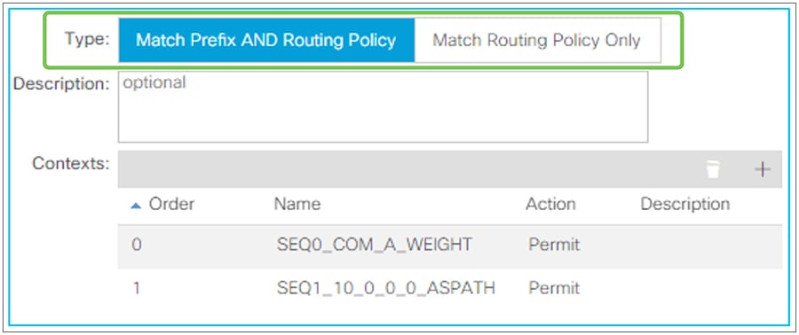
Route Profile Type in GUI (APIC Release 3.2)
Route Profile Type was introduced in APIC Release 1.2(2). Prior to 1.2(2), all Route Profiles (route maps) behave in the same way as “Match Prefix AND Routing Policy”.
When a Route Profile is associated to a component such as an L3Out EPG or an L3Out subnet, the Match Rules from the Route Profiles are merged into the internal route map for the component. See other sections (such as the “L3Out Transit Routing” section) for detailed examples of route maps internally created by other components. The Route Profile Type option defines how APIC merges the configured Route Profile rules into a route map deployed from other APIC policies such as an “Export Route Control Subnet” scope under the L3Out subnet.
● Match Prefix AND Routing Policy
This type will combine prefixes from the component that the Route Profile is associated to AND the match criteria configured in the Route Profile. For example, if the Route Profile is associated in the export direction to an L3Out EPG that has L3Out subnets 10.0.0.0/8 and 20.0.0.0/8 with an “Export Route Control Subnet” scope, the match clause of each internal route-map sequence on a leaf will have the match criteria of the prefixes from the associated component (10.0.0.0/8 and 20.0.0.0/8) AND from each Context Policy in the Route Profile.
● Match Routing Policy Only
This type will use only the match criteria configured in the Route Profile and ignore prefixes from the component to which the Route Profile is associated. For example, if the Route Profile is associated in the export direction to an L3Out EPG that has L3Out subnets 10.0.0.0/8 and 20.0.0.0/8 with an “Export Route Control Subnet” scope, APIC will ignore 10.0.0.0/8 and 20.0.0.0/8 and overwrite the internal route-map sequences for them with a new route map using the match criteria from the context policy in the Route Profile only. Some components that do not have a subnet configuration, such as BGP Route Dampening Policy, need to be configured with this type.
Figure 98 illustrates the differences of each type in an L3Out EPG.
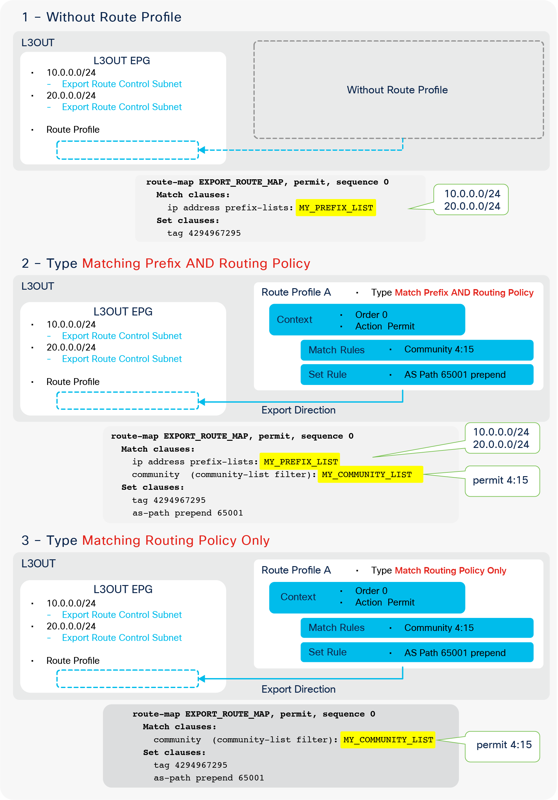
Comparison of Route Profile Types
As Figure 98 shows, “Type Match Routing Policy Only” (scenario 3) completely ignores the L3Out subnets with an “Export Route Control Subnet” scope. Hence, in this particular case, there is no point in configuring L3Out subnets with an “Export Route Control Subnet” scope. More guidance on which type should be used will be provided in the following sections for each scenario in associating Route Profiles.
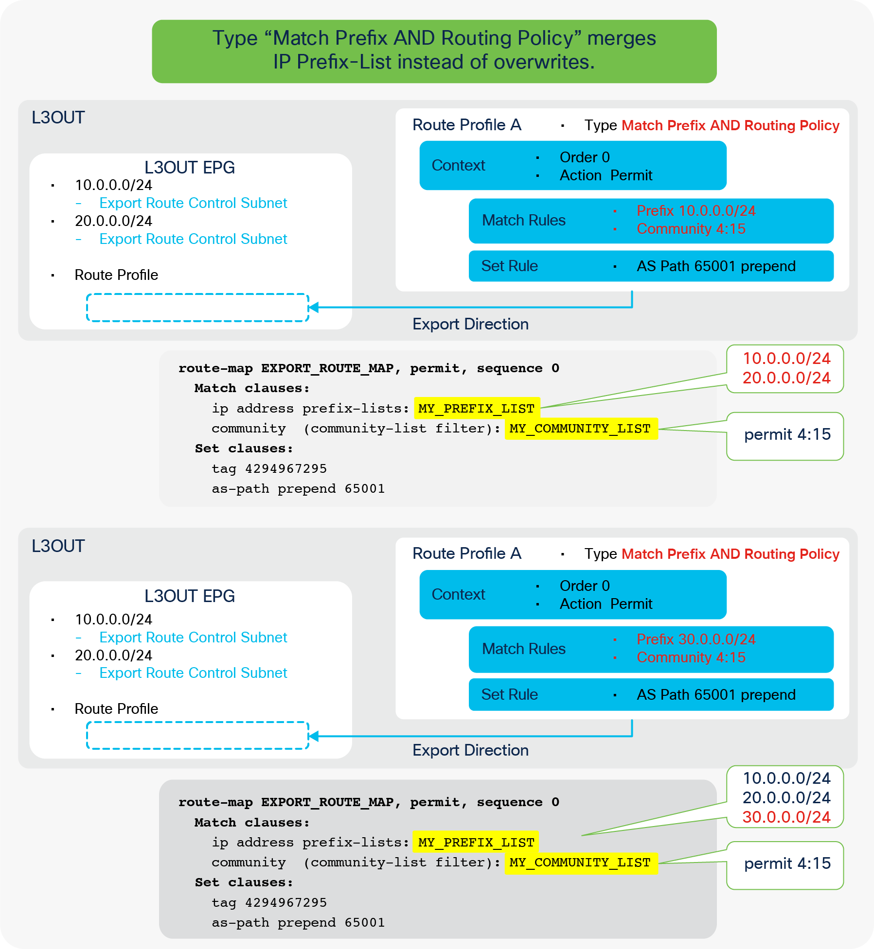
Explicit Prefix List and Match Prefix AND Routing Policy
Figure 99 illustrates the behavior of Type “Match Prefix AND Routing Policy” in conjunction with Explicit Prefix List (that is, match prefix criteria). As shown, this does not overwrite or take the “logical AND” between L3Out Subnets and prefixes in the Explicit Prefix List. The route map just merges prefixes from both objects.
Route Profile Match and Set Rules
Route Profile Match Rule options
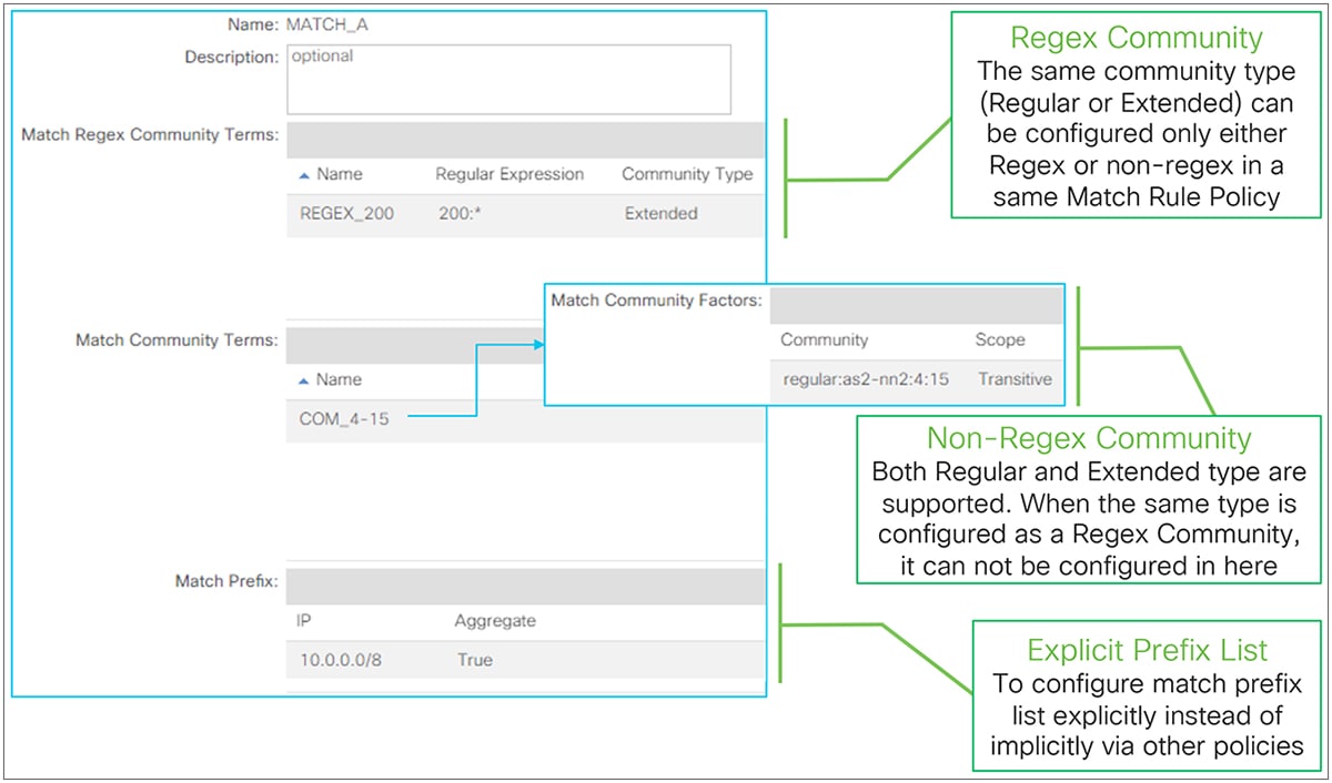
Route Profile Match Options in GUI (APIC Release 3.2)
Match Rules have been added to the Route Profile since the APIC Release 1.2(2). Prior to that release, only Set Rules were supported.
● Match Regex Community
This is to create match criteria using the regular expression (regex) community. If the same type of community (Regular or Extended) is configured as a non-regex community match in the same Match Rule Policy, it cannot be configured as a regex community match.
The standalone NX-OS equivalent commands are the following:
| ip community-list expanded <list-name> permit <regular expression> ip extcommunity-list expanded <list-name> permit <regular expression>
route-map <rm-name> match community <list-name> match extcommunity <list-name> |
● Match Community
This is to create match criteria using the BGP community. ACI supports both a Regular and an Extended community type. The community is in a format of AS2:NN2 (two-bytes AS and two-bytes user-defined Network Number) or AS4:NN2 (four-bytes AS number and two-bytes user-defined Network Number) in an extended community. The community syntax when configured on APIC is as follows:
◦ Regular: regular:as2-nn2:<2bytes AS number>:<2 bytes Network Number>
| Ex.) “regular:as2-nn2:65001:100” |
◦ Extended: extended:as4-nn2:<4 bytes AS number>:<2 bytes Network Number>
| Ex.) “extended:as4-nn2:65536:100” |
An Extended community type supports the following two scopes;
◦ Transitive: The community will be propagated across eBGP peering (that is, across AS’s).
◦ Non Transitive: The community will not be propagated across eBGP peering (that is, across AS’s).
The standalone NX-OS equivalent commands are the following:
| ip community-list standard <list-name> permit <as2:nn community> ip extcommunity-list standard <list-name> permit 4bytegeneric {transitive | nontransitive} <as4:nn community>
route-map <rm-name> match community <list-name> match extcommunity <list-name> |
● Match Prefix (Explicit Prefix List)
This is to create match criteria using the IP prefix-list. This option was introduced in APIC Release 2.1(1). It is referred to as Explicit Prefix List, in comparison to IP prefix-lists implicitly created by other APIC policies, such for “Export Route Control Subnet”.
When the “Aggregate” option is enabled, the IP prefix-list adds “le 32” to the prefix. This prefix does not have to be 0.0.0.0/0. This can be used as an alternative for “Aggregate Export/Import” for an “Export/Import Route Control Subnet” scope in case an aggregation is required for a non-0.0.0.0/0 subnet. Please remember that “Export/Import Route Control Subnet” scope only supports 0.0.0.0/0 to use “Aggregate Export/Import” option.
The standalone NX-OS equivalent commands are the following:
| ip prefix-list <list-name> permit <prefix>/<mask> {le 32}
route-map <rm-name> match ip address prefix-list <list-name> |
Route Profile Set Rule options
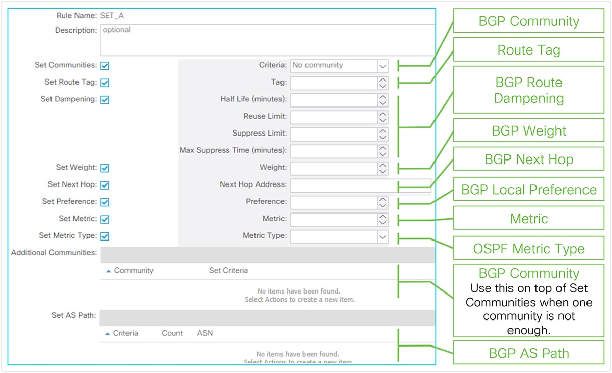
Route Profile Set options in GUI (APIC Release 3.2)
● Set Communities (BGP Community)
This is to set the BGP Community. The syntax is the same as for Match Community, mentioned above. The available options are as follows:
◦ No Community: This is to remove an existing community.
◦ Append Community: This is to append a community to existing ones.
◦ Replace Community: This is to replace an existing with a new community.
When multiple communities need to be set, use the Additional Communities option on top of this option.
The standalone NX-OS equivalent commands are the following:
| route-map <rm-name> set community <community> {none | additive] set extcommunity <extcommunity> 4bytes-generic transitive {additive} |
● Set Route Tag
This is to set a Route Tag. This does not apply for routes that are given a tag by the VRF Tag Policy such as routes advertised (exported) to the outside.
The standalone NX-OS equivalent commands are the following:
| route-map <rm-name> set tag <num> |
● Set Dampening (BGP Route Dampening)
This is to set parameters for BGP Route Dampening. See the “BGP Route Dampening” in the “L3Out BGP” section for details.
● Set Weight (BGP Weight)
This is to set the BGP weight. If the same BGP weight needs to be set for all routes from a particular BGP peer, the weight can be set in the BGP Peer Connectivity Profile instead. See the “BGP protocol options – neighbor-level” subsection for details.
The standalone NX-OS equivalent commands are the following:
| route-map <rm-name> set weight <num> |
● Set Next Hop (BGP Next Hop)
This is to overwrite the next-hop IP in BGP routes.
The standalone NX-OS equivalent commands are the following:
| route-map <rm-name> set ip next-hop <next-hop ip> |
● Set Preference (BGP Local Preference)
This is to set the BGP local preference.
The standalone NX-OS equivalent commands are the following:
| route-map <rm-name> set local-preference <num> |
● Set Metric
This is to set the metric for OSPF or BGP routes, or to set the minimum bandwidth for EIGRP routes.
The standalone NX-OS equivalent commands are the following:
| route-map <rm-name> set metric <num> |
● Set Metric Type (OSPF Metric Type)
This is to set the OSPF external metric type (Type 1 or Type 2). OSPF uses Type 2 by default, which does not include the cost (metric) to reach the ASBR that originated the external route, whereas Type 1 includes the cost to the ASBR.
The standalone NX-OS equivalent commands are the following:
| route-map <rm-name> set [type-1 | type-2] |
● Additional Communities
This is used on top of Set Community when multiple communities need to be set. This option was introduced in APIC Release 2.2(2). See Set Community for available configuration parameters.
● Set AS Path (BGP AS Path)
This is to prepend a BGP AS Path in BGP routes. This was introduced in APIC release 3.0(1). The available options are as follows:
◦ Prepend AS: This is to manually specify each AS number to prepend.
◦ Prepend Last-AS: This is to prepend automatically the last AS number multiple times.
The standalone NX-OS equivalent commands are the following:
| route-map <rm-name> set as-path prepend <AS> <AS> ... set as-path prepend last-as <count> |
Route Profile Match Rules AND/OR
This subsection explains how multiple match criteria within a Route Profile are handled. This is not regarding Route Profile Type “Match Prefix AND Routing Policy” or “Match Routing Policy Only”, which is regarding the L3Out subnet (Prefix) and the match criteria in the Route Profile. Instead, this is about the match criteria inside a single Route Profile.
The following Figure 102 shows when match criteria are handled as “AND” which means when multiple match criteria are configured in the same route-map sequence. In this situation, the match criteria need to be configured under a single Match Rule Policy in a single context policy.
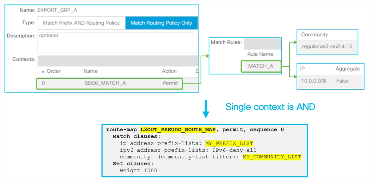
The following Figure 103 shows when match criteria are handled as “OR,” which means when multiple match criteria are configured in separate route-map sequences. In this situation, the match criteria need to be configured in separate context policies. The order option in each context defines which context (route-map sequence) is applied first.
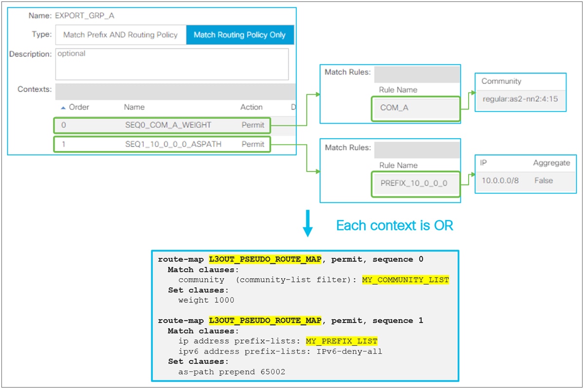
Route Profile OR Match Rules (part 1)
| Note: When Match Rules need to be “OR”, one can configure the match criteria in separate Match Rules in a single context policy. However, the order of match criteria will be indeterministic in this case. Thus, choosing this configuration for “OR” is not recommended, unless the order of each match criteria does not matter. |
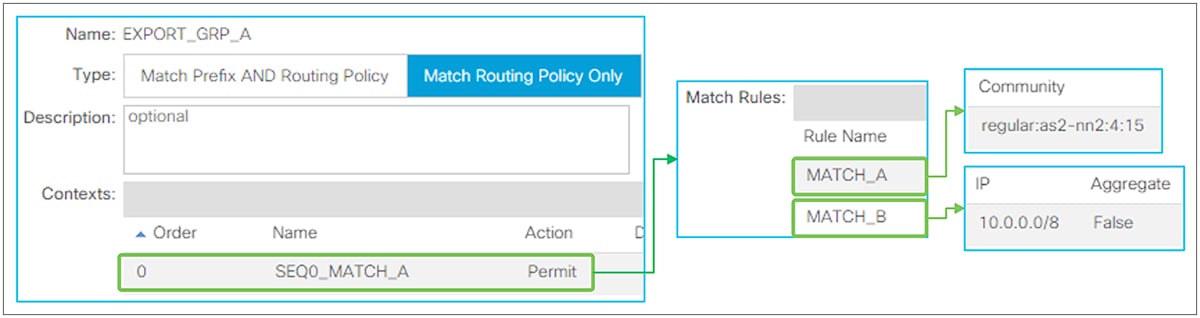
Route Profile OR Match Rules (part 2)
Route Profile on L3Out EPG (export/import routes)
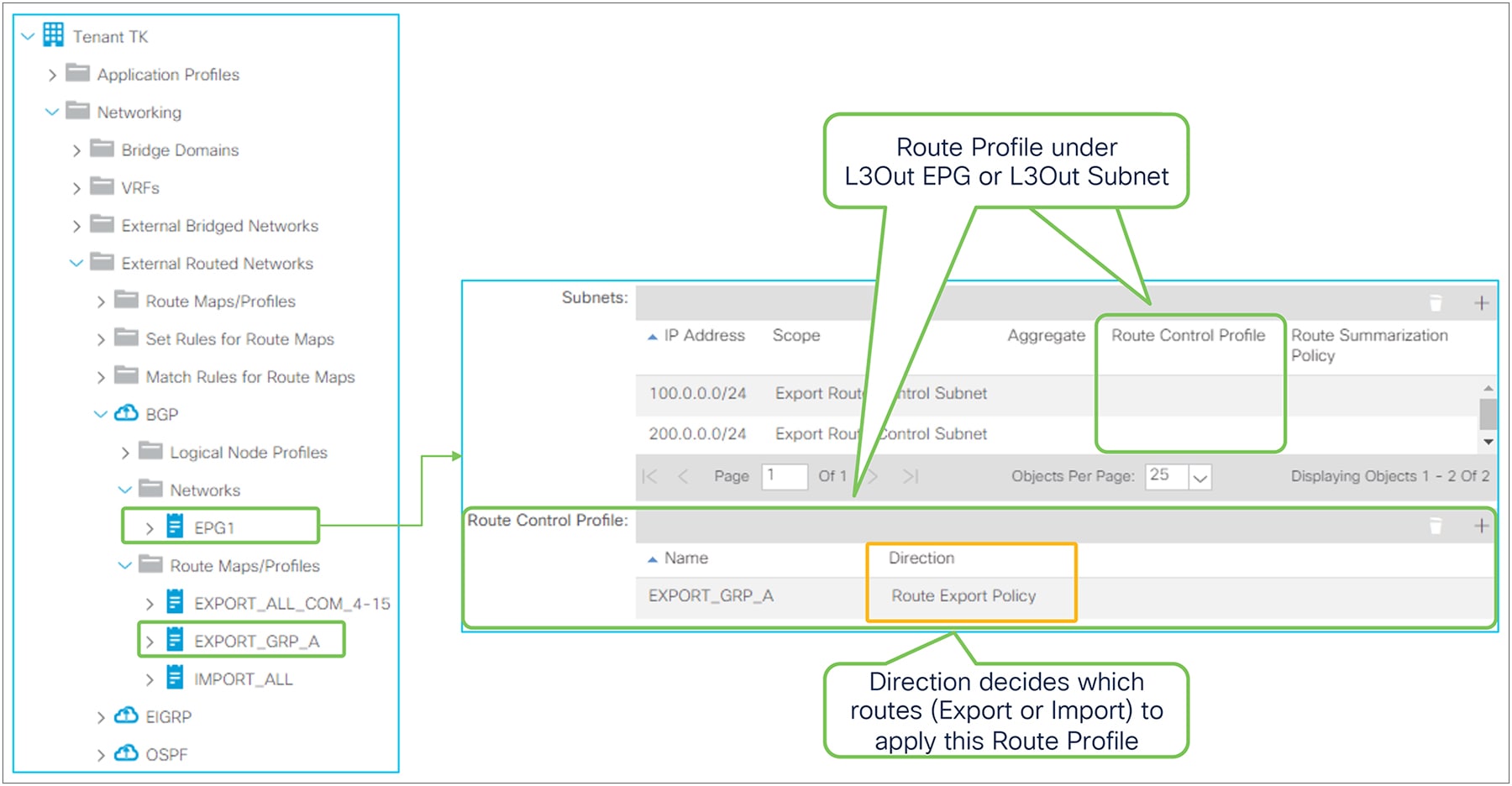
Route Profile on L3Out in the GUI (APIC Release 3.2)
In an L3Out EPG, the Route Profile under each L3Out is used to add Match and/or Set Rules to the internal route-maps used for an “Export Route Control Subnet” or “Import Route Control Subnet” scope. See the “L3Out Transit Route” section for details on each subnet scope. There are two elements in Route Profile for L3Out EPG. The first is Direction and the second is the component to which a Route Profile is associated.
● Route Profile Direction
This decides which subnet type the Route Profile is applied to.
◦ Route Export Policy: The Route Profile is applied to subnets with an “Export Route Control Subnet” scope.
◦ Route Import Policy: The Route Profile is applied to subnets with an “Import Route Control Subnet” scope.
● Route Profile Association
This decides the scope of the Route Profile. The following describes the behavior when the Route Profile uses Type “Match Prefix AND Routing Policy” without Explicit Prefix List (that is, match prefix criteria), which is the recommended configuration.
◦ L3Out EPG
The Route Profile is applied to all of the configured L3Out subnets with matching direction scope in this L3Out EPG. In Figure 105, the Route Profile “EXPORT_GRP_A” with Export direction on the L3Out EPG1 will be applied to both L3Out subnets 100.0.0.0/24 and 200.0.0.0/24 that have an “Export Route Control Subnet” scope. If the direction of the Route Profile was Import in Figure 105, the Route Profile is not applied to those two subnets because of their nonmatching directions.
◦ L3Out Subnet
The Route Profile is applied to this particular subnet. If the subnet scope and Route Profile direction do not match, the Route Profile is not applied.
| Note: On top of these two association levels, there is one more level. That is a special Route Profile called default-export or default-import, which will be applied to the entire L3Out and associated BDs. See the following subsection for details on default-export/import. When Route Profiles are associated to multiple levels, a more granular scope will be prioritized. This means L3Out Subnet > L3Out EPG > default-export/import. |
The following series of diagrams (Figure 106 through Figure 110) illustrates some recommended configurations and how the rules from the Route Profiles are applied. In these examples, L3Out 1 in the middle is trying to advertise a BD1 subnet and external routes from L3Out 2.
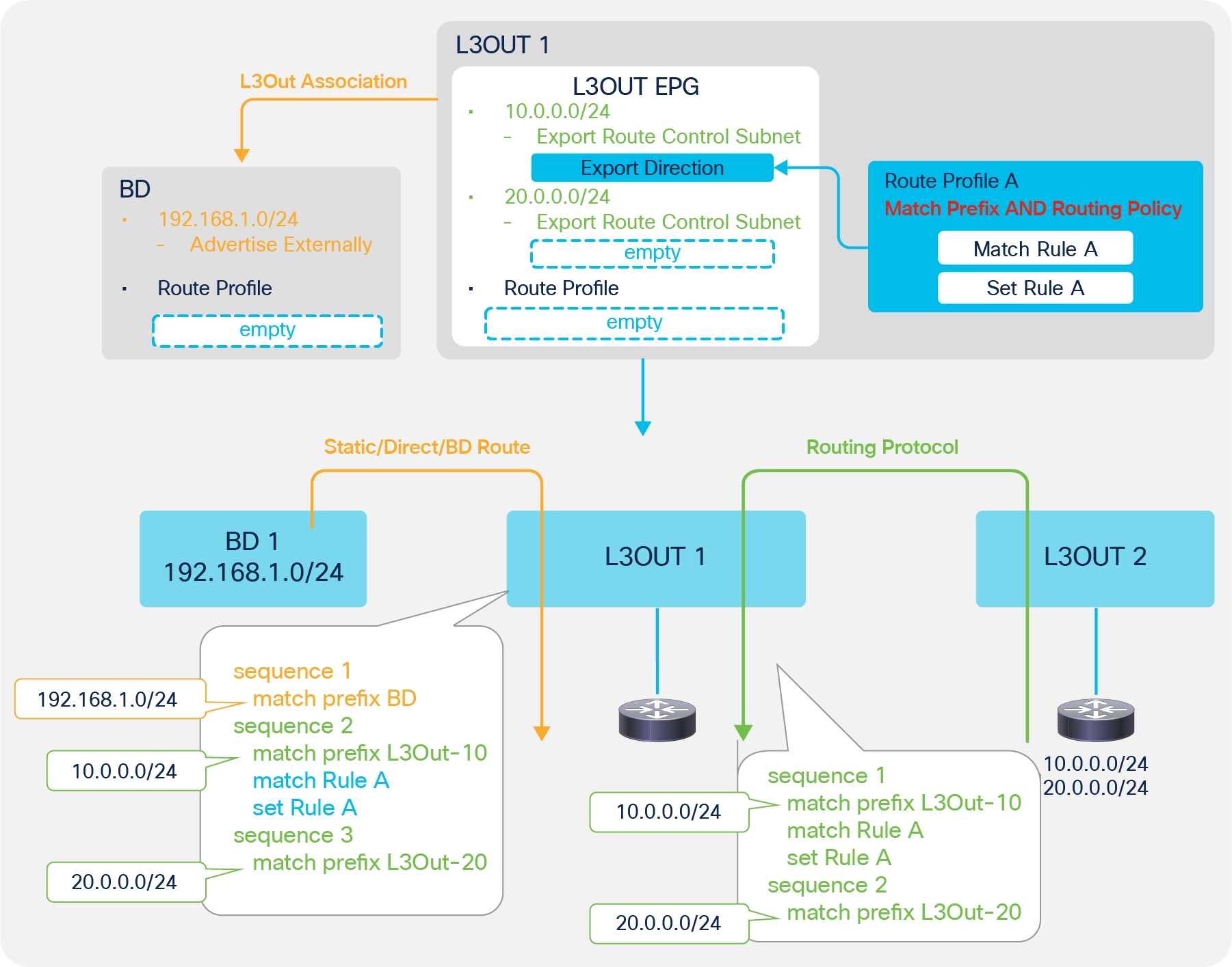
Route Profile Example on the L3Out subnet (Match Prefix AND Routing Policy)
In this example, the Route Profile is applied only to the L3Out subnet 10.0.0.0/24 via Route Profile A. It is also applied to a part of the redistribution for BD subnets (the orange arrow in Figure 106) since the “Export Route Control Subnet” scope could be used to advertise BD subnets. In this example, the Route Profile doesn’t do anything for BD subnet announcements because the BD subnet is different from the IP prefix-list subnet (match prefix L3Out-10 in the picture), and the advertisement is configured via the L3Out association to the BD.
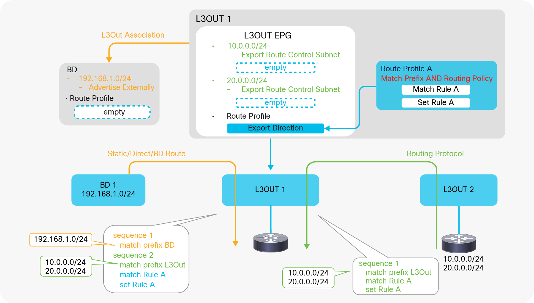
Route Profile Example on the L3Out EPG (Match Prefix AND Routing Policy)
In this example, the Route Profile is applied to all of the L3Out subnets that have a matching direction scope “Export Route Control Subnet”. It is also applied to a part of the redistribution for the BD subnets (the orange arrow in Figure 107) since the “Export Route Control Subnet” scope could be used to advertise the BD subnets. In this example, the Route Profile does not do anything for BD subnet announcements because the BD subnet is different from the IP prefix-list subnet (match prefix L3Out in the picture), and the advertisement is configured via the L3Out association to the BD. In case an “Export Route Control Subnet” scope is used to advertise the BD subnets instead of the L3Out association, the rules from the Route Profile such as Set Rule A will apply to the BD subnet advertisement as well.
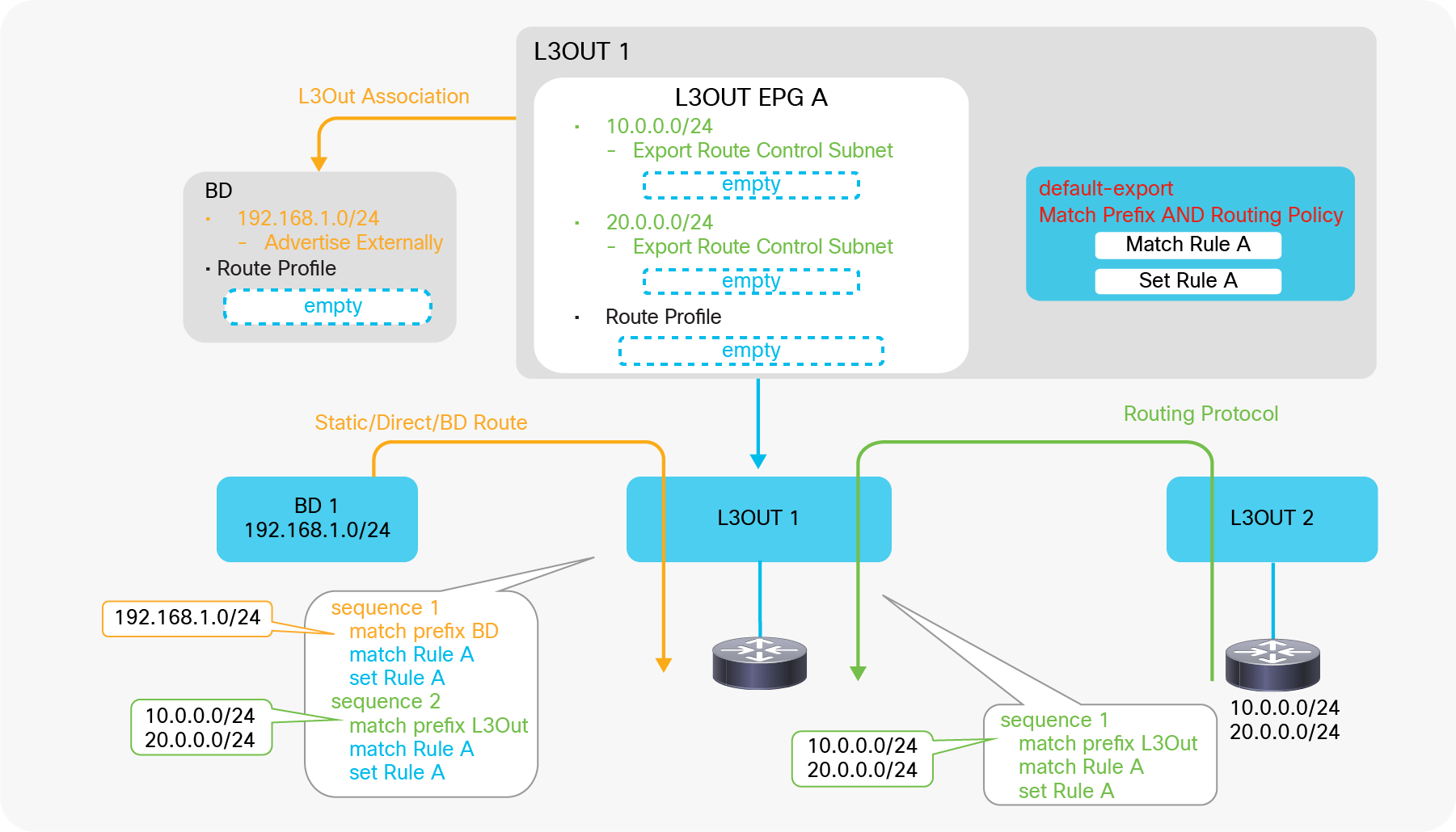
Route Profile Example on the L3Out default-export (Match Prefix AND Routing Policy)
In this example, the Route Profile is default-export, and its type is “Match Prefix AND Routing Policy”. Hence, ACI applies the Route Profile to all subnets related to this L3Out 1, including the BD subnets with L3Out association and an “Advertise Externally” scope.
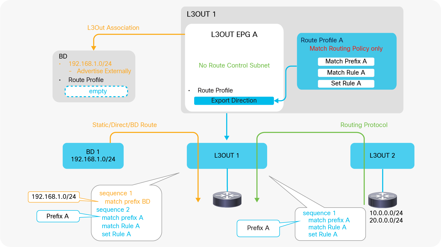
Route Profile Example on L3Out EPG (Match Routing Policy Only)
In this example, the Route Profile is of the type “Matching Routing Policy Only”, hence ACI creates rules based purely on the Route Profile due to “Match Routing Policy Only”. The Route Profile is applied to L3Out routes (the green arrow in Figure 109) and also to the redistribution of the BD subnet (the orange arrow in Figure 109), since the Route Profile could be used to advertise the BD subnet as well (see the “ACI BD subnet advertisement” section). In this example, it does not affect the BD subnet because the prefix (match prefix A in the picture) is different from the BD subnet, and the advertisement is achieved via the L3Out association to the BD. Also, there is no point in creating an L3Out subnet with an “Export Route Control Subnet” scope in this L3Out EPG because it will be ignored in both Transit Routing and BD subnet advertisement due to the Route Profile with “Match Routing Policy Only” in the Export Direction.
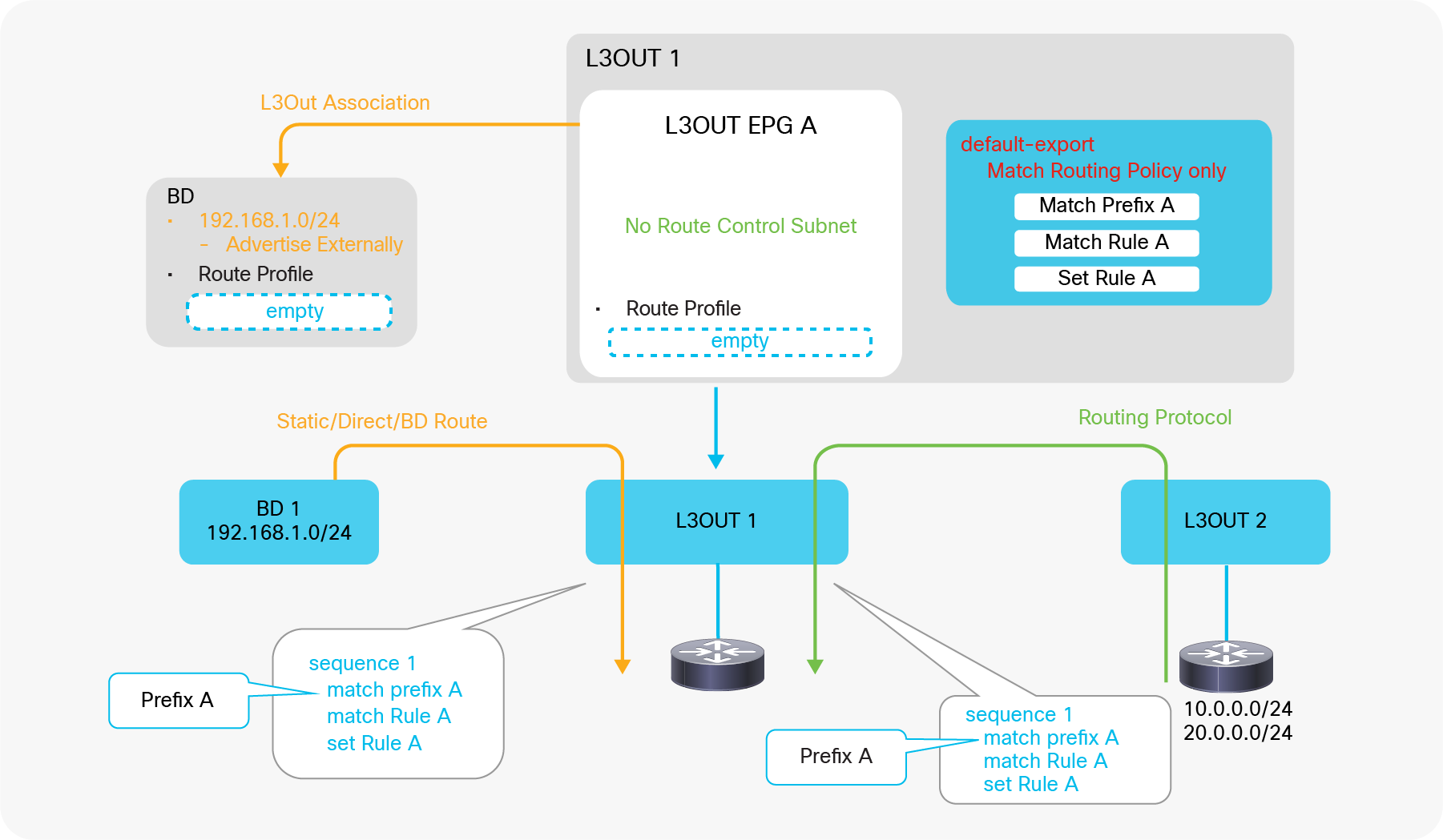
Route Profile Example on L3Out default-export (Match Routing Policy Only)
In this example, ACI creates rules based purely on the Route Profile because of “Match Routing Policy Only”. Also, due to default-export, ACI overwrites any other rules related to L3Out 1. In this example, the L3Out association has no effect and is not required, since the BD subnet redistribution from the L3Out association to the BD is ignored and overtaken by default-export with “Match Routing Policy Only”. Because of this, the administrator should include the BD subnet (192.168.1.0/24) in the Explicit Prefix List in default-export (Match Prefix A in Figure 110). However, the “Advertised Externally” scope in the BD subnet is still required.
The configuration in Figure 110 is recommended in case a Route Profile is used to control Transit Routing and BD subnet advertisement.
| Note: There are multiple ways to apply Route Profiles to all possible routes: 1. Use default-export/default-import with Explicit Prefix List of 0.0.0.0/0 and an Aggregate option (Figure 110). 2. Apply a custom Route Profile with Explicit Prefix List of 0.0.0.0/0 and an Aggregate option to L3Out EPG (Figure 109). 3. Apply a custom Route Profile to L3Out EPG or L3Out subnet for 0.0.0.0/0 with an “Export/Import Route Control Subnet” scope and an “Aggregate Export/Import” option. (Supported only from APIC Release 4.2 onward.) When using the second option, please be aware of the following behavior: ● It is applied to routes from routing protocols (the green arrow in Figure 109 and Figure 110) ● It is not applied to static routes, directly connected subnets, and BD subnets (the orange arrows in Figure 109 and Figure 110). This is because the internal route-map for routing protocol redistribution and others (static and direct routes) are different. See the “Internal route-map for Transit Routing” in the “L3Out Transit Routing” section for details. |
Route Profile Type and L3Out EPG/subnet
The following is a general recommendation regarding the combination of Route Profile Type and Explicit Prefix List. The recommendation is to use an Explicit Prefix List only with the “Match Routing Policy Only” type to avoid overlapping configurations.
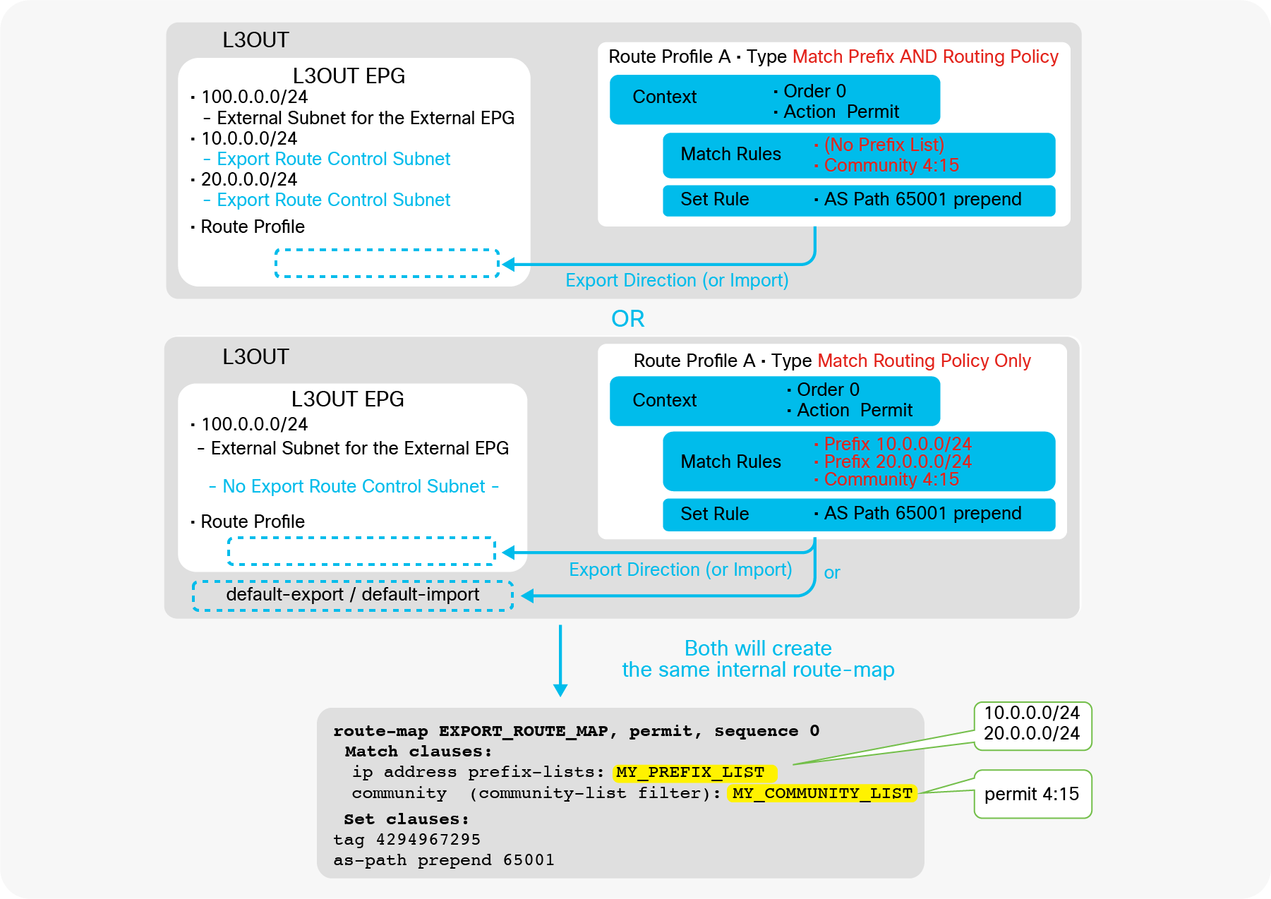
L3Out Route Profile Type differences and recommendations
● With Type “Match Prefix AND Routing Policy”
The recommendation is to use L3Out subnets with an “Export / Import Route Control Subnet” scope exclusively without an Explicit Prefix List (that is, match prefix criteria) to apply Set Rules or additional Match Rules such as communities. Otherwise, the configuration will not be easy to consume and maintain, because it merges prefixes from L3Out subnets and the Explicit Prefix List, as Figure 99 illustrates.
● With Type “Match Routing Policy Only”
The recommendation is to use Explicit Prefix List exclusively without L3Out subnets with an “Export / Import Route Control Subnet” scope because subnets with that scope will be ignored, as Figure 98 shows. It is also recommended to use this type under L3Out always with “default-export” or “default-import” Route Profile instead of a custom Route Profile, because there is no point in using a custom Route Profile and applying it to the L3Out EPG since the L3Out EPG configurations (that is, subnets with an “Export / Import Route Control Subnet” scope) are ignored anyway. See the “default-export / default-import” subsection below for details on these two specific Route Profiles.
| Note: The recommendation regarding L3Out subnets is specific to the “Export / Import Route Control Subnet” scope. Other scopes such as “External Subnets for the External EPG” are not affected and can be used regardless of Route Profile Type. |
default-export / default-import
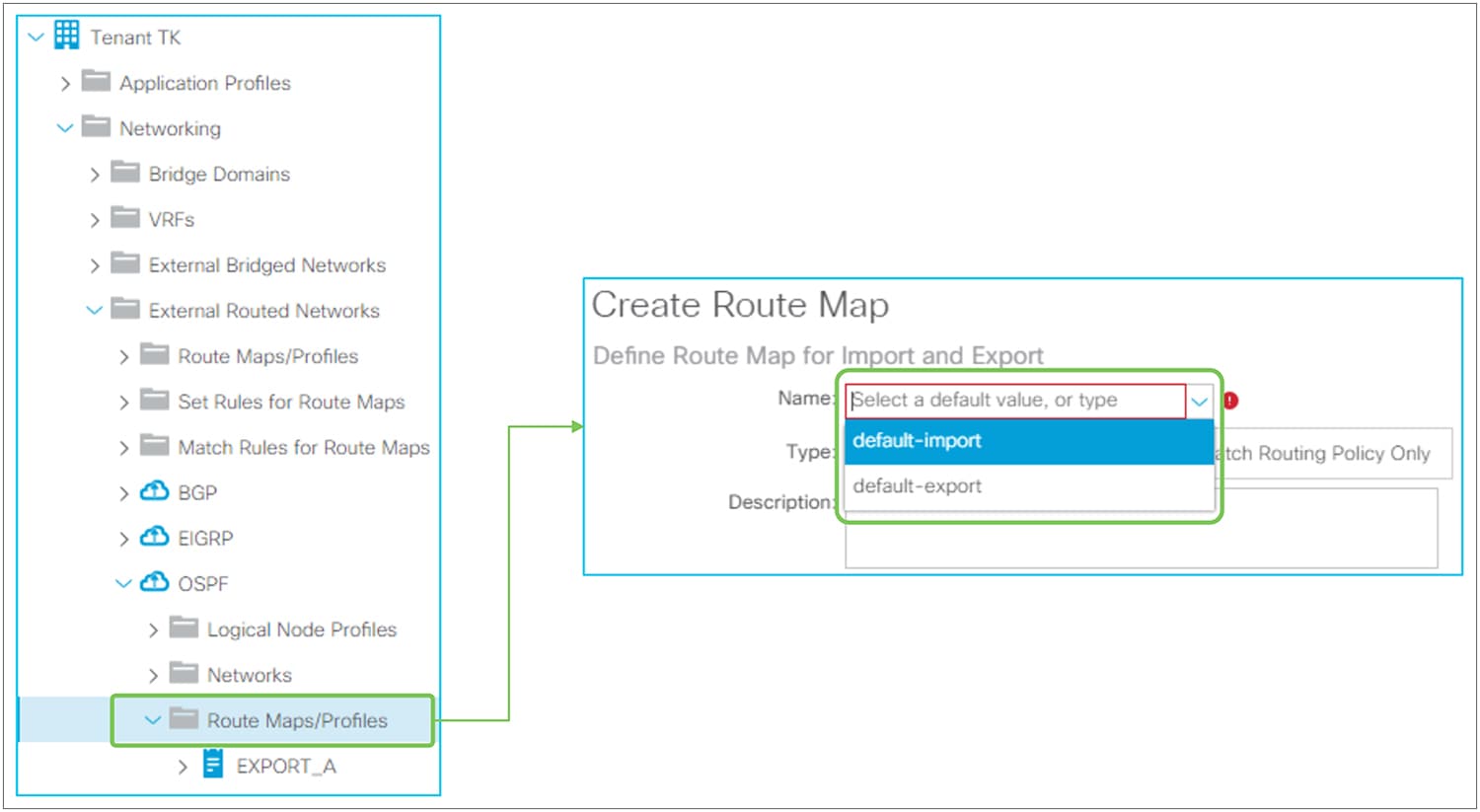
Route Profile default-export / default-import in the GUI (APIC Release 3.2)
When creating a Route Profile / Route Map under L3Out, there are two default policy names in the dropdown menu: default-export and default-import. The configurations of these Route Profiles are the same as in other Route Profiles; the difference is that these two special Route Profiles will take effect without association to other components, such as L3Out EPG or L3Out subnet.
| Note: Prior to APIC Release 4.2, the dropdown menu for default-export and default-import was also displayed on the Tenant-level Route Profile. However, it was not applied anywhere and did not take effect. Starting with APIC Release 4.2, the dropdown menu for default-export and default-import on the Tenant-level Route Profile was removed, and these two special Route Profiles are made available only under L3Out. |
When created with Type “Match Prefix AND Routing Policy”, default-export will be applied to all L3Out subnets with an “Export Route Control Subnet” scope (default-import for “Import Route Control Subnet”) without having to associate it to each L3Out subnet or L3Out EPG. The default-export Route Profile will also be applied to BD subnets with an “Advertised Externally” scope in a BD that has association to this L3Out. If each component (L3Out EPG, L3Out subnet, BD subnet) already has its own Route Profile, those Route Profiles will be prioritized over the default-export or default-import Route Profile. Figure 113 shows the internal route-map when default-export is used with type “Match Prefix AND Routing Policy” under L3Out.
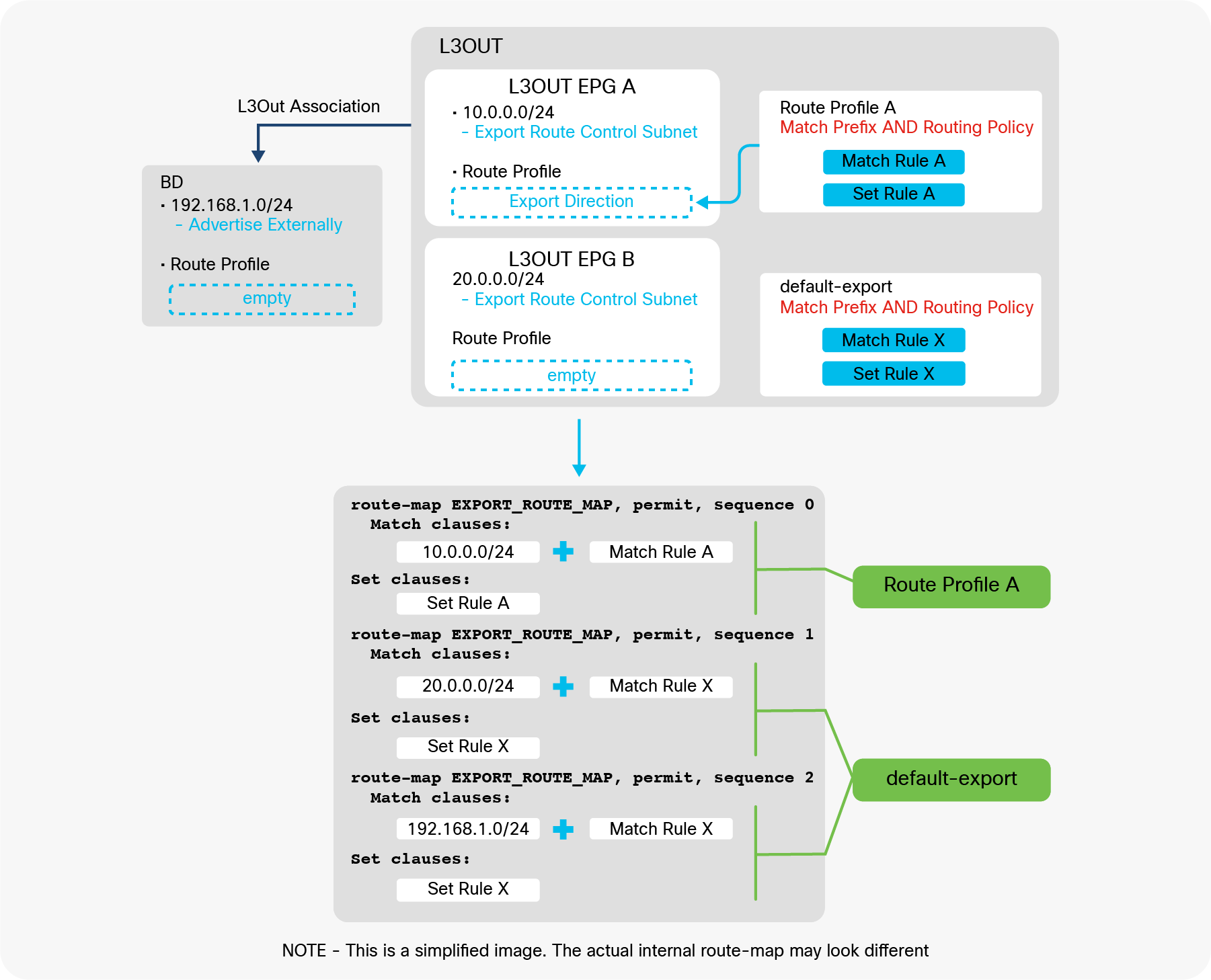
L3Out default-export Route Profile with Match Prefix AND Routing Policy
When it is created with Type “Match Routing Policy Only”, it will create a route-map sequence with its own match criteria only and ignore all other internal route-map sequences for L3Out subnet with an “Export Route Control Subnet” scope (or “Import Route Control Subnet” for default-import). The default-export Route Profile will also ignore the configuration of BD subnets with an “Advertise Externally” scope in the BD to which the L3Out is associated. If each component (L3Out EPG, L3Out subnet, BD subnet) has its own Route Profile, they will be prioritized over the default-export or default-import Route Profile. Figure 114 shows the internal route-map when default-export is used with type “Match Routing Policy Only” under L3Out.
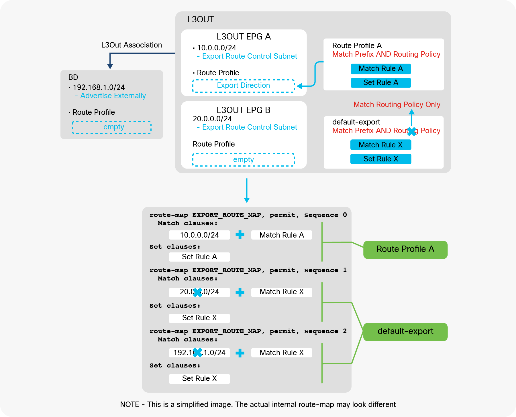
L3Out default-export Route Profile with Match Routing Policy Only
default-export for simple routing control (the recommended configuration)
This subsection explains how default-export can simplify the configuration of subnet advertisement in ACI.
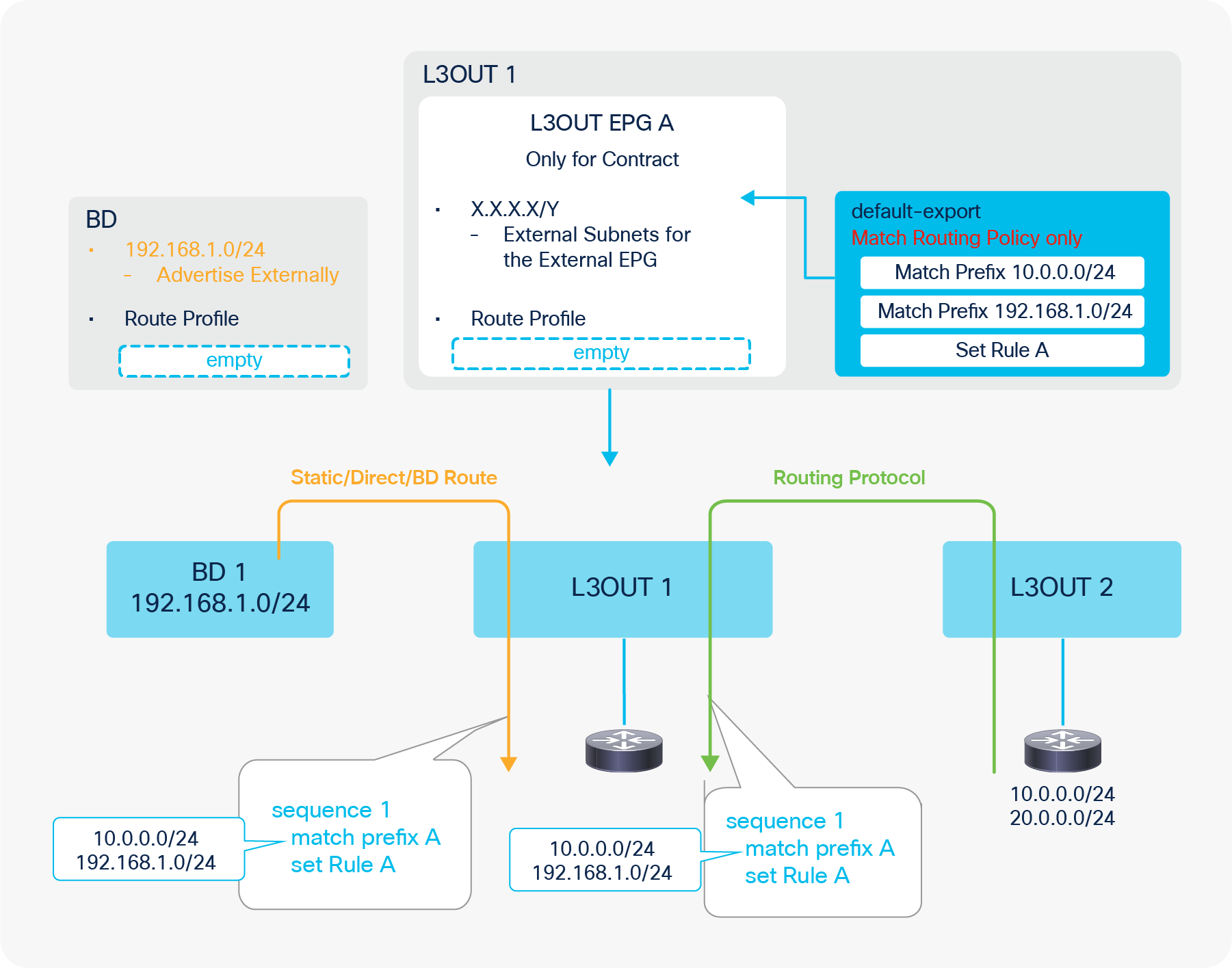
Default-export for BD Subnets and Transit Routing
Figure 115 illustrates an example of how the default-export Route Profile with type “Match Routing Policy Only” simplifies the configuration to advertise subnets from the L3Out. As mentioned in the previous sections, the default-export with type “Match Routing Policy Only” ignores other subnet advertisement configurations such as an “Export Route Control Subnet” scope and the L3Out association to the BD. Then, without merging with other configurations, the default-export is applied to internal route-maps for both Static/Direct/BD subnets (the orange arrow in the picture) and routes from routing protocols (the green arrow in the picture). Hence, it can be used as a single source of controls for any subnet advertisements from the L3Out. In this example, the default-export Route Profile is configured with the BD subnet (192.168.1.0/24) and one of the external routes from L3Out 2 (10.0.0.0/24). Without any other configurations in the L3Out, the L3Out advertises those routes to the outside. Please note that the “Advertise Externally” scope in the BD subnet is still required. If set rules need to be applied to those routes, it can be easily accomplished by adding a set rule in the same Route Profile (default-export) as shown in the picture.
With this approach, the L3Out EPG can focus on the security (contracts) management with an “External Subnets for the External EPG” scope for subnets that are learned via the L3Out as opposed to the routes it is advertising to the outside. L3Out shared service (VRF route leaking) still needs to be configured in the L3Out EPG.
Please also see the “ACI BD subnet advertisement” section for comparisons of the configuration options to advertise BD subnets.
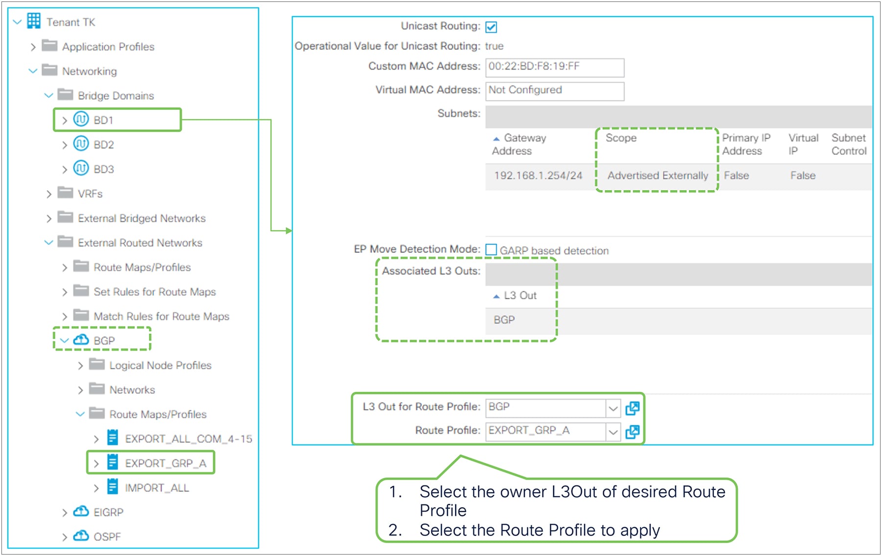
Route Profile on BD in the GUI (APIC Release 3.2)
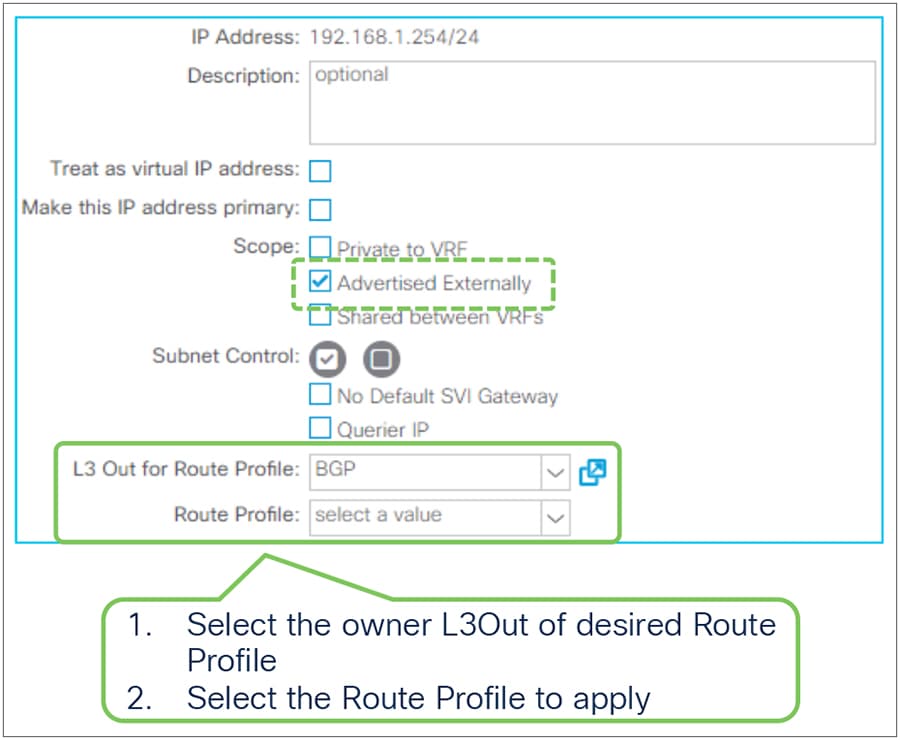
Route Profile on BD subnet in the GUI (APIC Release 3.2)
In the BD, the Route Profile is used to add match and/or set rules to internal route-maps used for advertising BD subnets to the outside via L3Out association to BD, which redistributes BD subnets to the L3Out routing protocol. See the “ACI BD subnet advertisement” section for details on internal route-maps for this.
Unlike the Route Profile on L3Out EPG, there is no direction in the BD. You just need to specify the L3Out that owns the Route Profile to be applied first, since a BD may be associated to multiple L3Outs.
| Note: The same recommendation on Route Profile Type from Route Profile on L3Out EPG is applied to the BD. When using an Explicit Prefix List, the recommendation is to use Type “Match Routing Policy Only”. In such scenario, it is equivalent to scenario 3 in Figure 69 from the “ACI BD subnet advertisement” section. |
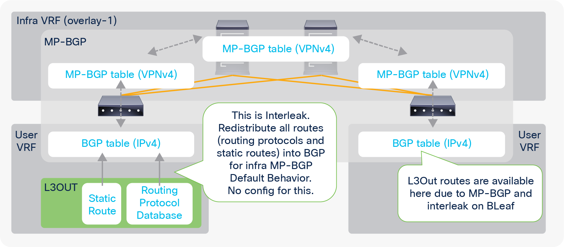
As briefly mentioned in the “Infra MP-BGP” section, interleak is an internal automatic redistribution for MP-BGP from an L3Out since the first release of Cisco ACI. An option to apply a Route Profile to interleak was introduced in APIC Release 1.2(2). This option is supported for OSPF and EIGRP L3Outs. The BGP L3Out does not need interleak because the routes are already in the BGP table. Applying a Route Profile to interleak of static routes was introduced in APIC Release 4.2(1).
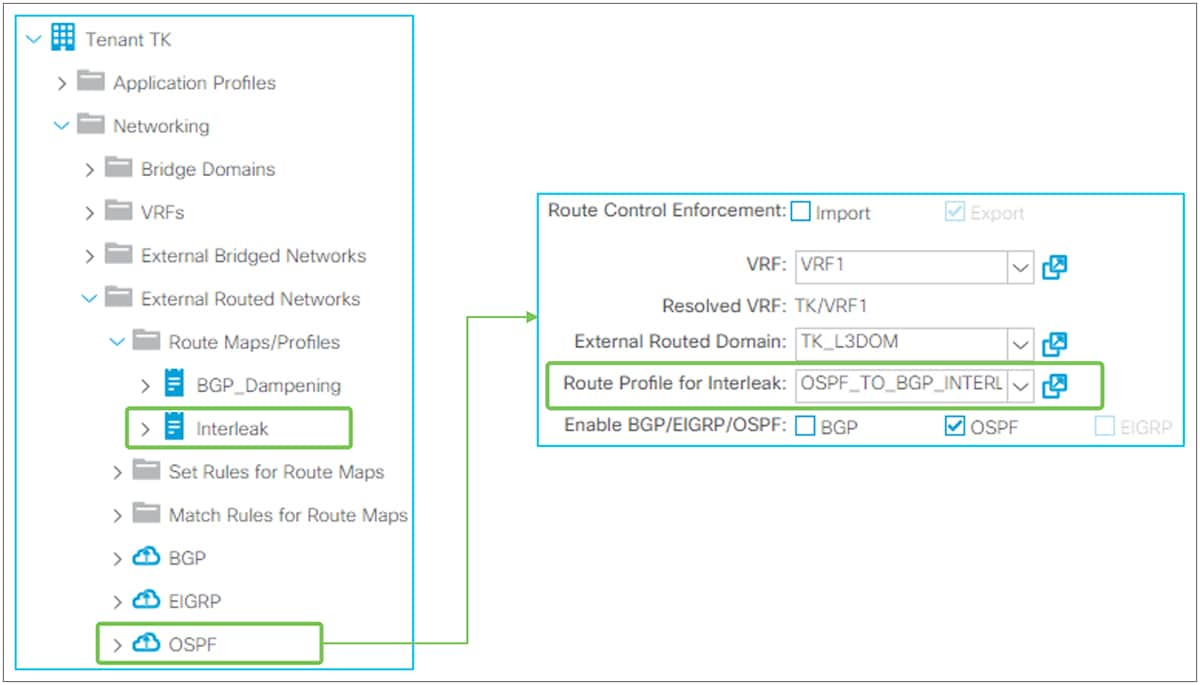
Route Profile for interleak in the GUI (APIC Release 3.2)
For interleak, a Route Profile is associated to an L3Out itself, as Figure 119 shows. The Route Profile used for interleak is the tenant-level Route Profile instead of the one under L3Out.
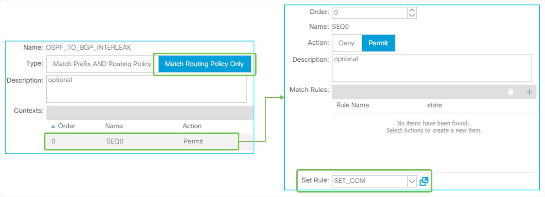
Route Profile contents for interleak
Route Profile for interleak needs to use the “Match Routing Policy Only” type; there is no point in using “Match Prefix AND Routing Policy” because there is no subnet information that it can refer to in objects unlike the case for a Route Profile on an L3Out EPG. Route Profile for interleak is intended to set a community rule that will traverse infra MP-BGP to other border leaf switches so that other border leaf switches can selectively perform Transit Routing based on the community.
Figure 121 shows an example of a Route Profile for interleak use case where L3Out 2 assigns different metrics for the same external route from two other L3Outs (1 and 3).
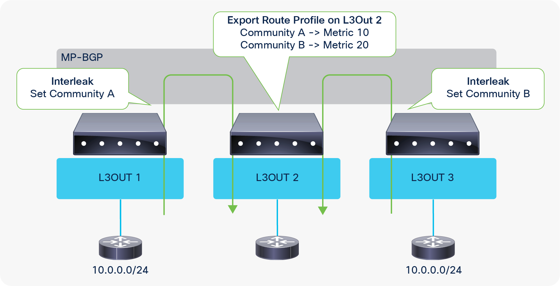
Route Profile for interleak use case
L3Out shared service (VRF route leaking)
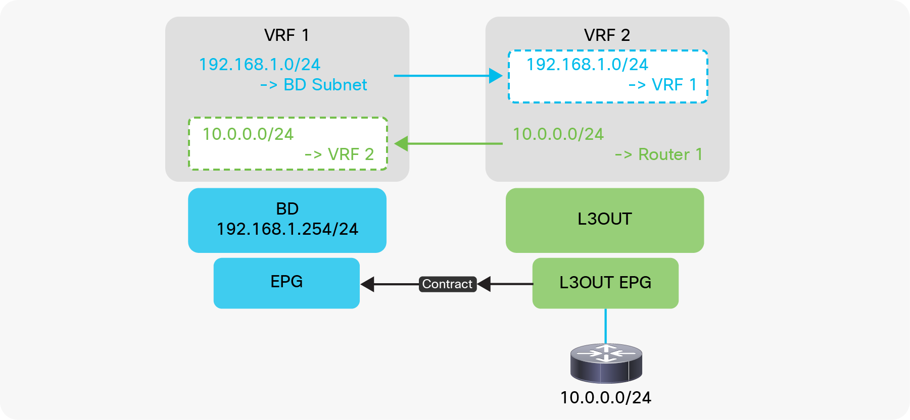
L3Out shared service (VRF route leaking)
VRF route leaking with L3Out was introduced in APIC release 1.2(1). This feature allows the leaking of external routes learned via L3Out to another VRF so that it can be consumed by EPGs in another VRF. This feature is also referred to as L3Out shared service or shared L3Out because it is sharing a service behind L3Out to another VRF. Figure 122 shows the typical use case where L3Out is providing a service (10.0.0.0/24) to an EPG in another VRF (VRF 1). The EPG on the left in VRF 1 could be another L3Out in VRF1 instead that consumes the external routes from VRF 2, which is a combination of L3Out Transit Routing and shared service. See some limitations from “Shared Layer 3 Out” section in ACI Fundamentals Guide.
| Note: Prior to this feature, the term “shared service” used to imply that a user tenant used a component from the Tenant Common; for example, user tenant A using VRF A, defined in Tenant Common, for BDs in tenant A. This allowed endpoints in tenant A to belong to the same IP space (Tenant Common VRF A) as services (endpoints or L3Outs) in Tenant Common. In this case, no VRF route leaking was required for cross-tenant communication because all the components were in the same VRF A. However, since the release of VRF route leaking, “shared service” tends to imply VRF route leaking rather than sharing services from Tenant Common. VRF route leaking can be within a tenant or between tenants. The original shared service using the Tenant Common is still a valid design and configuration. |
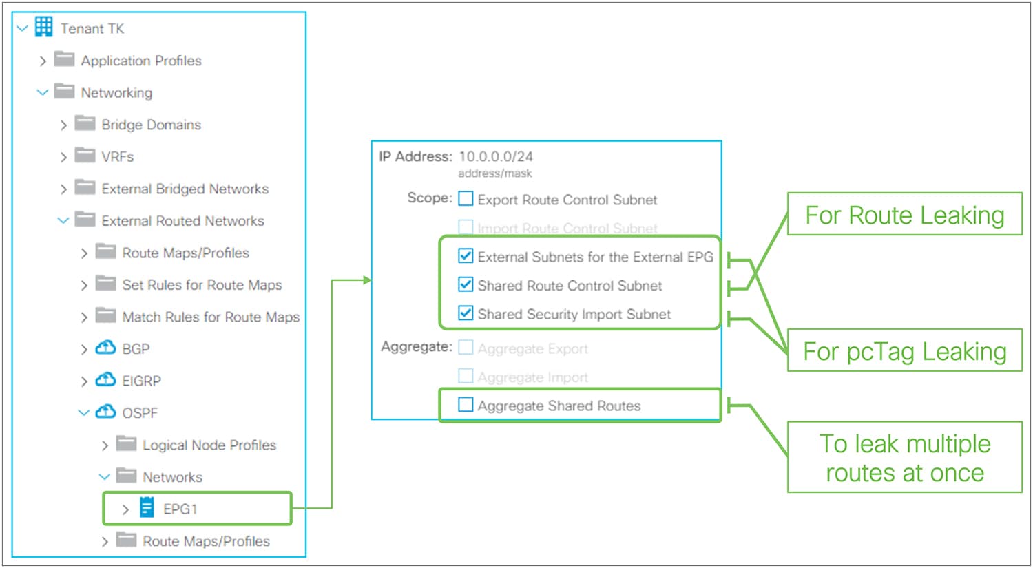
L3Out subnet shared service scope in the GUI (APIC Release 3.2)
There are two L3Out subnet scopes for the L3Out shared service:
● Shared Route Control Subnet: This is to leak the routes in the routing tables into another VRF.
● Shared Security Import Subnet: This is to leak prefix-to-pcTag mapping into another VRF. This needs to be used with an “External Subnets for the External EPG” scope.
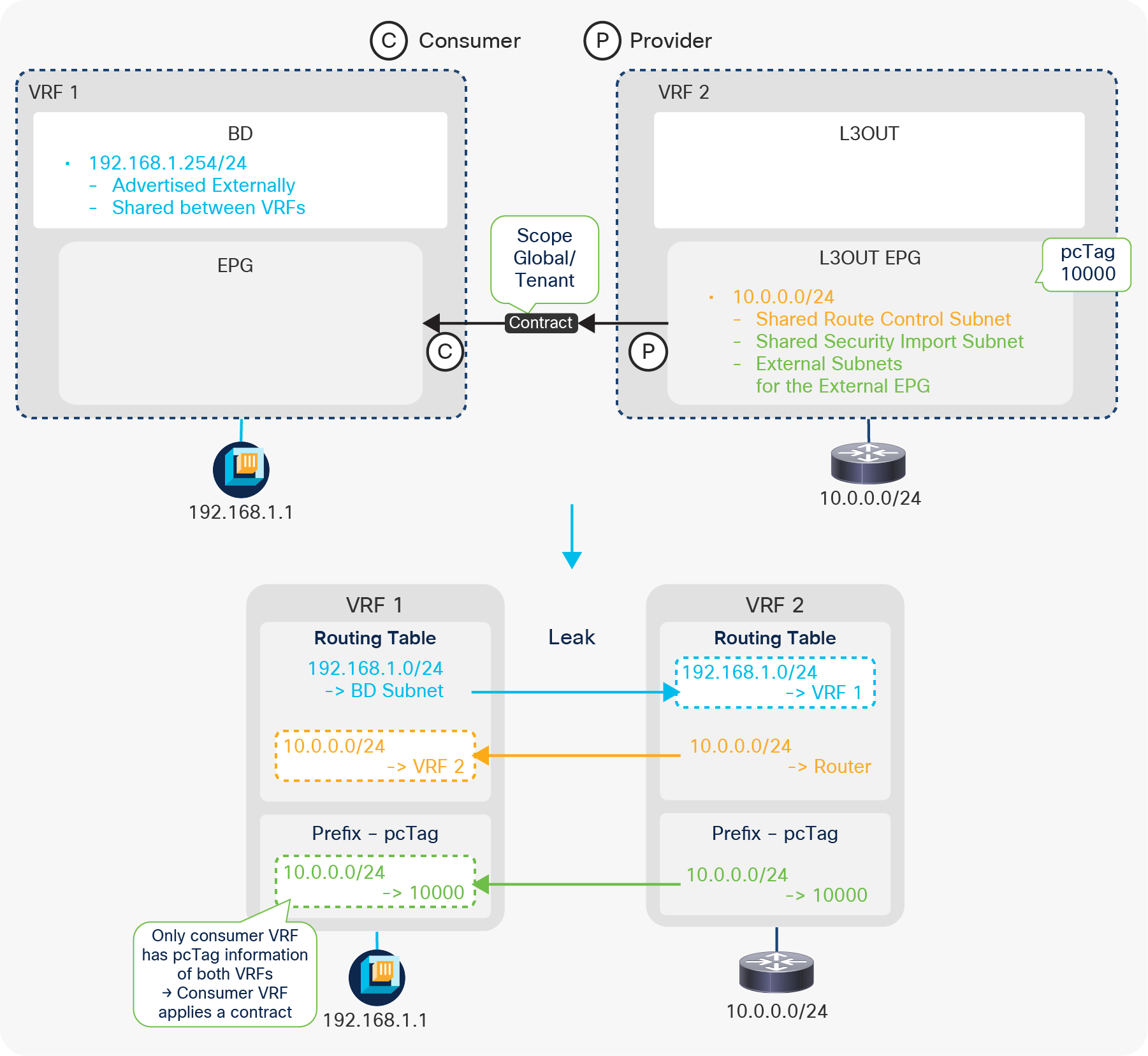
Example diagram of a shared L3Out configuration
Figure 124 illustrates the most basic shared L3Out configuration, in which an L3Out provides a service (subnet 10.0.0.0/24) from VRF 2 to endpoints in VRF 1. As mentioned previously, there are two parts in shared L3Out: route leaking and prefix-pcTag mapping leaking for contracts.
Route leaking
This is to leak routes between routing tables in each VRF, like a normal router. The three components to make this happen are the following:
● L3Out Subnet with “Shared Route Control Subnet” scope
This is to define which external routes (or static routes) in the routing table to leak. This is the part in orange (10.0.0.0/24 in VRF 2) in Figure 124. If the route is not in the routing table, it will not be leaked.
● BD Subnet with “Shared between VRFs” and “Advertised Externally” scope
This is to define which BD subnet to leak. This is the part in blue (192.168.1.0/24 in VRF 1) in Figure 124. The “Shared between VRFs” scope is the one to leak the route to another VRF. The “Advertised Externally” scope is also required so that the leaked BD subnet will be advertised to external routers via the L3Out in VRF 2. In this case, L3Out association to the BD or any other BD subnet advertisement configuration mentioned in Figure 69 is not required.
● Contract between the L3Out EPG and an EPG in the BD
This is to define between which VRFs these routes need to be leaked, on top of the main purpose of contracts; to allow traffic. The scope of the contract needs to be Global when the two VRFs are in different tenants, or Tenant when the two VRFs are in the same tenant. The scope Application Profile is not applicable here since the L3Out EPG is not part of any application profile.
Prefix-pcTag (contract) leaking
This is to leak the prefix-pcTag mapping. By default, pcTag is unique only within a VRF, and an EPG in VRF 1 and an L3Out EPG in VRF 2 (in the example shown in Figure 124) could use the same pcTag. Hence, ACI has a concept called global pcTag that is unique across all VRFs in the ACI fabric. There are two parts in shared L3Out to utilize this global pcTag for contracts across VRFs.
● L3Out Subnet with “Shared Security Import Subnet” scope
This is to define which prefix-pcTag mapping to leak. Hence, the L3Out subnet must be configured with an “External Subnets for the External EPG” scope as well to create the prefix-pcTag mapping in the first place. This is the part in green (10.0.0.0/24 to pcTag 10000) in Figure 124. See the “L3Out contracts” section for details on prefix-pcTag mapping.
● Contract between the L3Out EPG and an EPG in the BD
This is to define which VRF the prefix-pcTag mapping needs to be leaked to and which EPG needs to use a global pcTag. Once a contract with the scope Global or Tenant is consumed and provided across VRFs, the pcTag of the provider EPG is changed to a global pcTag. In the example in Figure 124, the L3Out EPG in VRF 2 is assigned a global pcTag. This global pcTag is used to create a prefix-pcTag mapping in VRF 2 and leaked to VRF 1 due to the “Shared Security Import Subnet” scope.
This implies that the contract is always applied on the consumer VRF side that has the pcTag information for both the consumer and the provider sides. The provider side (VRF 2 in Figure 124) will not be aware of the pcTag (EPG) of the endpoints in the consumer VRF and will always allow leaked traffic, assuming that the consumer side will take care of it. In the example in Figure 124, there will be no prefix-pcTag mapping table entry for the endpoint 192.168.1.1, because the prefix-pcTag mapping table is only for L3Out external routes, and the endpoints use the endpoint table.
Figure 125 shows a GUI configuration summary of this basic example.
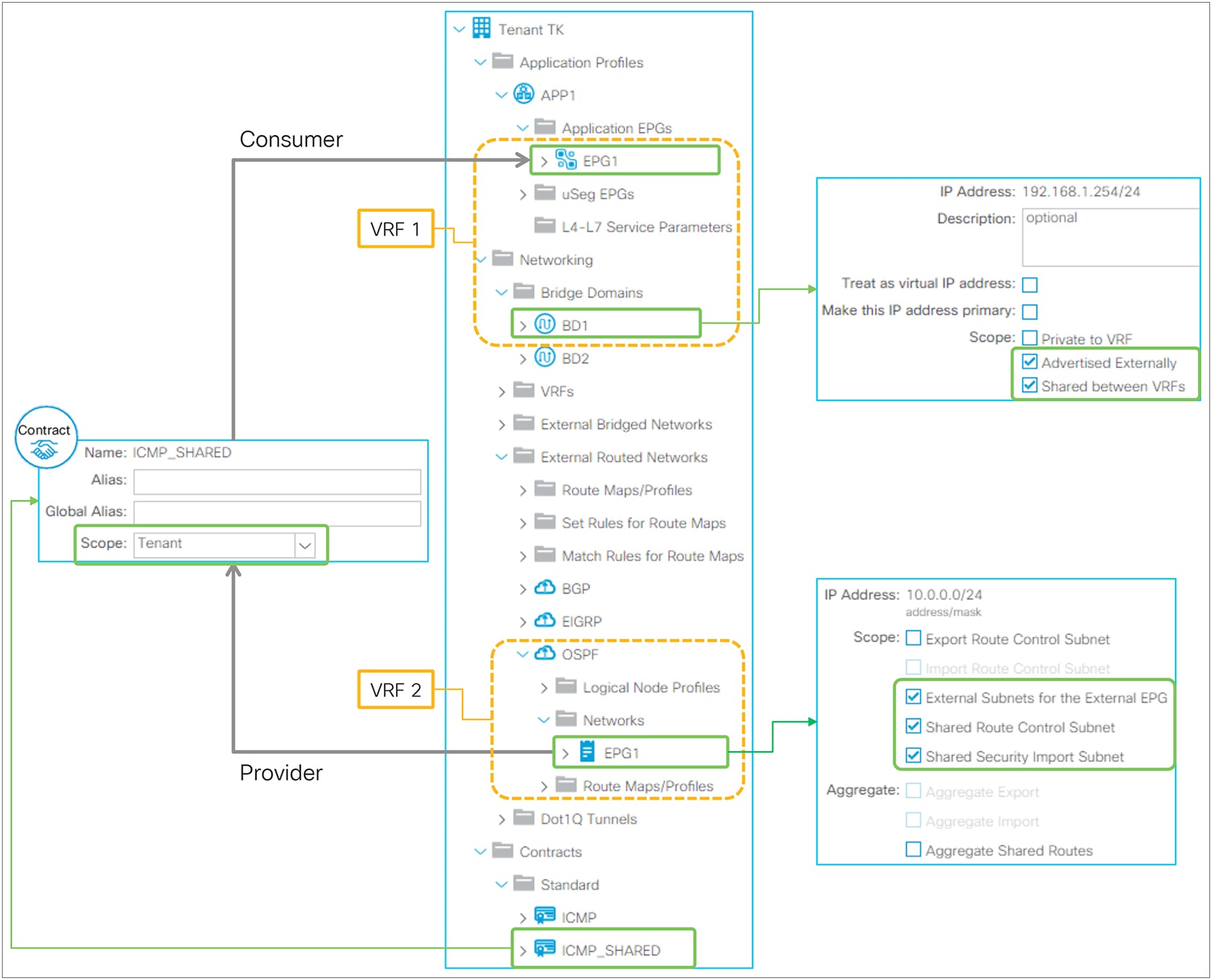
Example of a configuration of shared L3Out in the GUI (APIC Release 3.2)
| Note: A global pcTag uses a number lower than, while a normal pcTag uses a number higher than, 0x4000 (16384). The scope of a normal pcTag is per VRF so that the same number can be reused in multiple VRFs for scalability. When a normal pcTag is changed to a global pcTag due to a contract on an existing EPG, there may be a small amount of traffic disruption due to rewriting of all of the contract rules on the switches that have the new global pcTag. |
“Shared Route Control Subnet” and “Shared Security Import Subnet”
The “Shared Route Control Subnet” and “Shared Security Import Subnet” scopes are typically configured on the same L3Out subnet entry. However, users can configure the more granular “Shared Security Import Subnet” scope than the “Shared Route Control Subnet” scope in case different contract needs to be applied for the subset of the leaked subnets. For example, the following configuration is to leak 10.0.0.0/8 in a routing table into another VRF, but the prefix-pcTag mapping is created for 10.1.0.0/16 and 10.2.0.0/16 respectively so that different contracts can be applied for each prefix.
● 10.0.0.0/8 with a “Shared Route Control Subnet” scope
● 10.1.0.0/16 and 10.2.0.0/16 with a “Shared Security Import Subnet” scope (and an “External Subnets for the External EPG” scope)
However, a “Shared Security Import Subnet” scope cannot be less granular than a “Shared Route Control Subnet” scope, such as 10.0.0.0/4 in this example.
“Aggregate Shared Routes”
This scope is used with a “Shared Route Control Subnet” scope. Just like a “Export Route Control Subnet” scope, a “Shared Route Control Subnet” scope also internally uses an IP prefix-list, hence it is an exact match. When an “Aggregate Shared Routes” scope is enabled with a “Shared Route Control Subnet” scope, it adds “le 32” in the IP prefix-list entry that will match with any subsets of the configured subnet. Unlike an “Export Route Control Subnet” scope, this aggregate option for shared routes can be used not only for 0.0.0.0/0 but also for non-0.0.0.0/0 subnets.
Shared L3Out configuration options
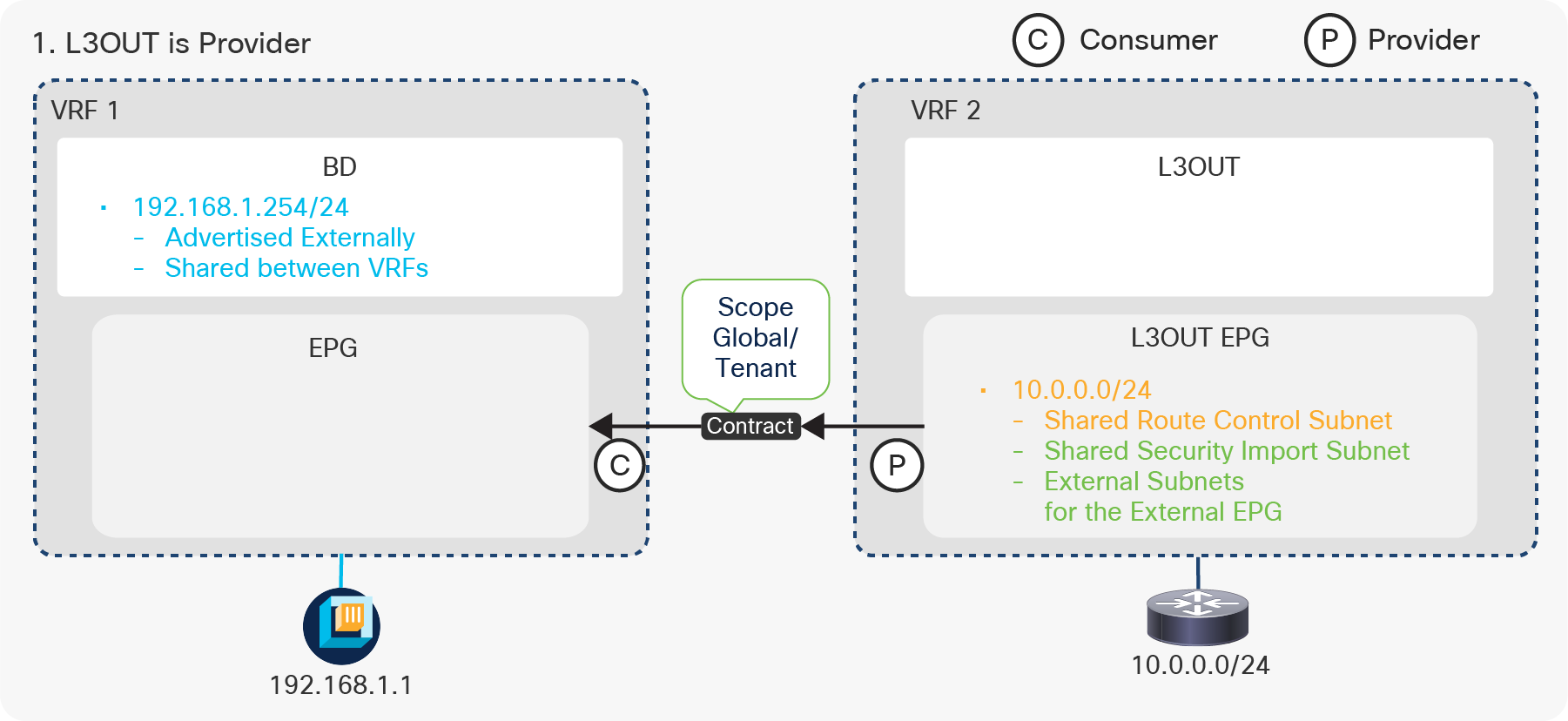
Shared L3Out configurations (1. L3Out is Provider)
The first option is using L3Out as the provider. This is the most basic configuration, as explained above. The L3Out is the provider; the EPG is the consumer. See the “Basic configuration example” above for details.
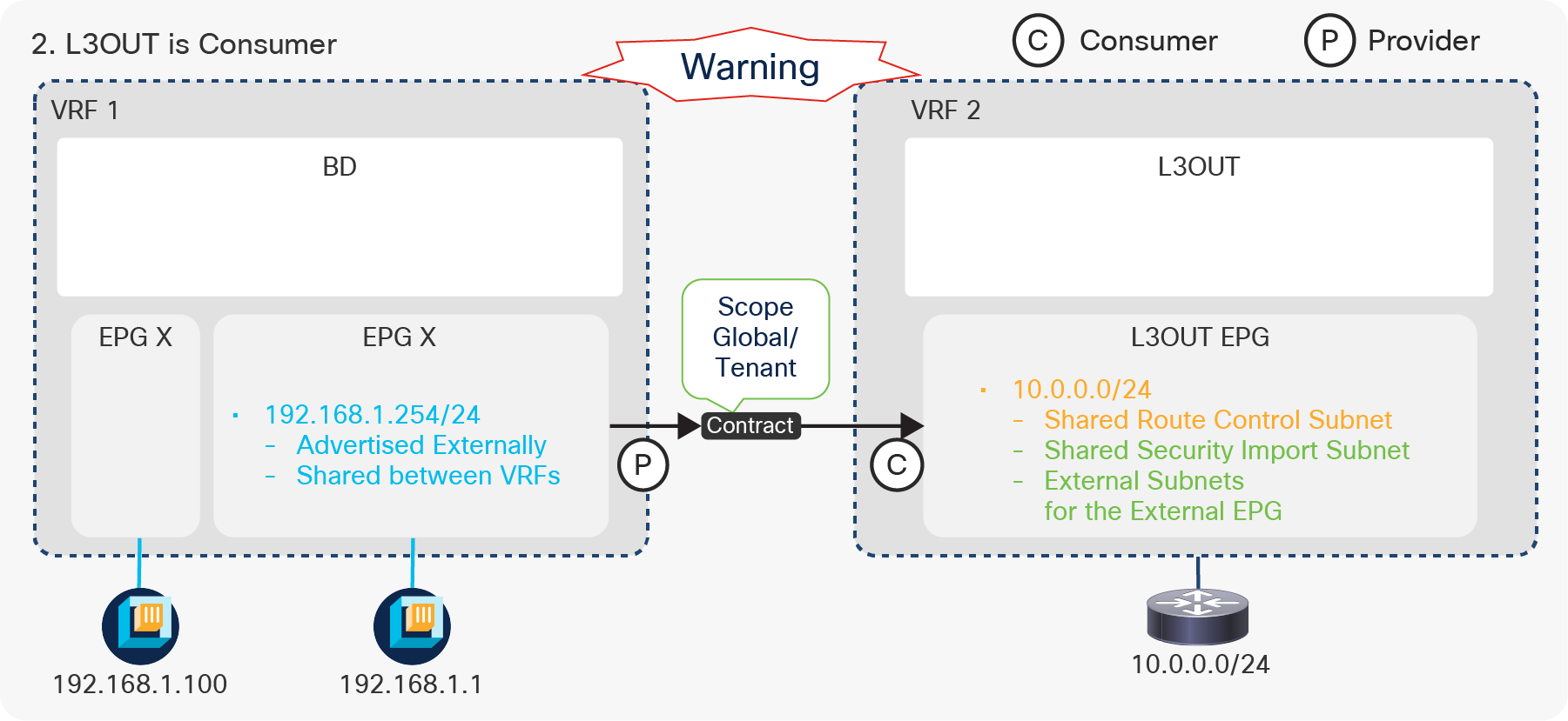
Shared L3Out configurations (2. L3Out is Consumer)
The other option is to use the L3Out as the consumer and the EPG as the provider. With this option, a BD subnet is configured under EPG 1, since EPG 1 is the provider (see the configuration guide for VRF Route Leaking between normal EPGs). EPG X has an endpoint in the same subnet, but it does not have a contract with VRF 2. Please note that even though the subnet is configured under the EPG, the subnet is deployed on leaf switches as a BD SVI, and other EPGs under the same BD can also use the same subnet. This configuration where the L3Out EPG is the consumer has a caveat because of pcTag usage and how contracts are applied. With this design, even though EPG 1 is a provider, not only EPG 1 but also the L3Out EPG will use a global pcTag (EPG X still uses a normal pcTag). A caveat on how contracts are applied is described below:
● Both the consumer and the provider VRF will have the same contract rule and a contract will be applied on an ingress VRF.
● In the consumer VRF (VRF 2), the global pcTag of EPG 1 will be tied to the BD (EPG) subnet (192.168.1.0/24). This means that traffic from the L3Out EPG in VRF 2 to any IP in the 192.168.1.0/24 subnet will be allowed in VRF 2 even if the destination IP does not belong to EPG 1. For example, when the packet to 192.168.1.100 that belongs to EPG X instead of EPG 1 enters VRF 2, ACI will get a pcTag based on the leaked subnet 192.168.1.0/24. This pcTag is the leaked pcTag of EPG 1 that actually has the contract for the shared L3Out. Then, VRF2 allows the packet using the leaked pcTag, even though the packet destination does not belong to the leaked EPG.
The recommendation to avoid this problem is to configure a smaller subnet that only includes the IP addresses of EPG 1 instead of the entire BD subnet. “No Default SVI Gateway” should be enabled for this smaller EPG subnet to avoid having an unnecessary secondary IP address on the BD SVI. Figure 128 illustrates an example of a smaller EPG subnet. In this case, the BD subnet 192.168.1.254/24 should be configured under the BD instead without the “Advertised Externally” and “Shared between VRFs” scopes so that the BD can still provide the pervasive gateway for EPGs such as EPG X.
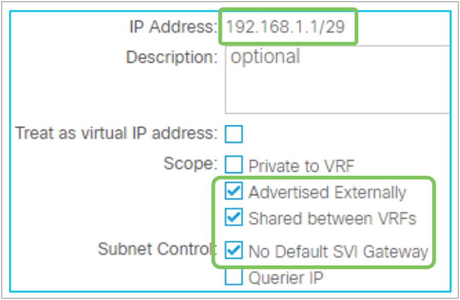
Smaller subnet under an EPG with No Default SVI Gateway
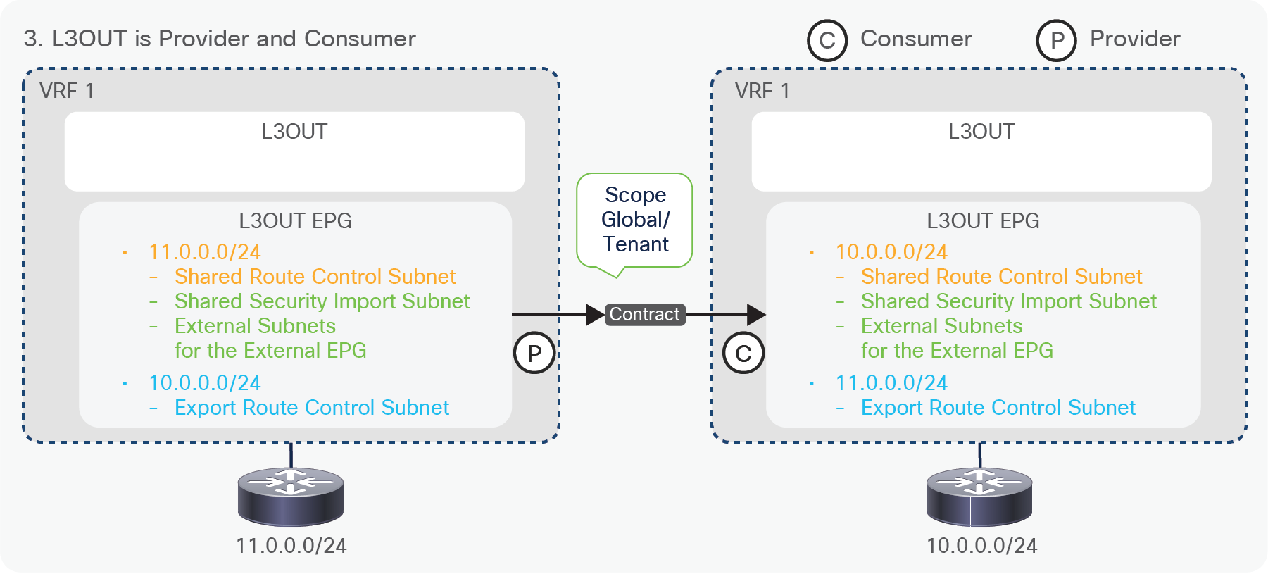
Shared L3Out configurations (3. L3Out is Provider and Consumer / Transit Routing)
The third option consists in configuring Transit Routing between different VRFs. This is a Transit Routing and shared service design combined. This configuration has been supported since APIC Release 2.2(2). To complete the communication, a normal Transit Routing configuration (an “Export Route Control Subnet” scope or a Route Profile such as default-export for the leaked route) also needs to be configured on each VRF so that the leaked routes can be advertised to the outside.
Advanced shared L3Out configuration options
Advanced configuration 1 (L3Out EPG separation)
Figure 130 illustrates a bad example of a configuration, where only a subset of external routes accessible between VRFs. In this example, the requirements are the following:
● VRF 2 has intra-VRF communication between L3Out (10.0.0.0/24) and an EPG (172.16.1.1)
● Only half of the L3Out routes (10.0.0.128/25) should be able to communicate between VRFs
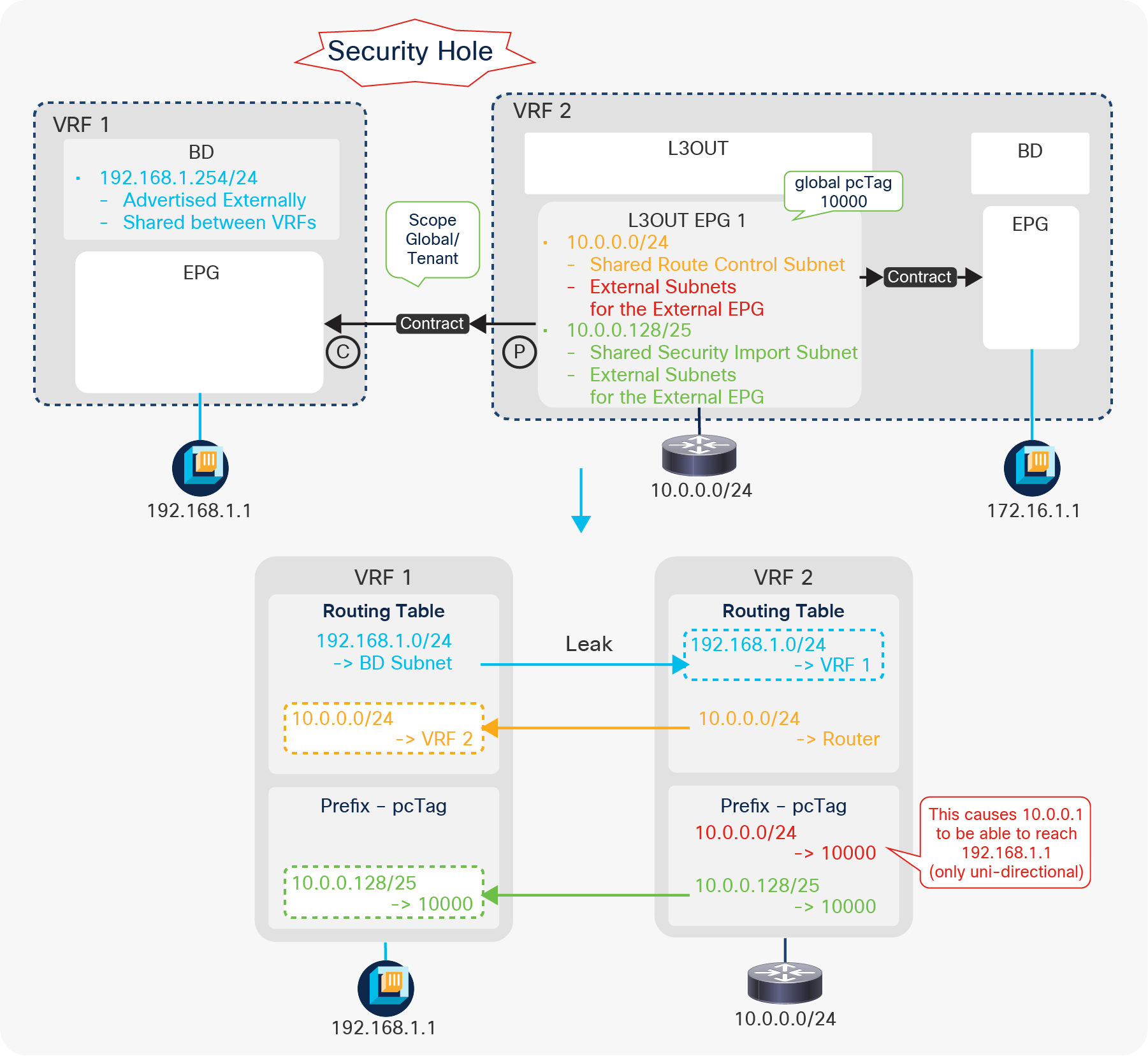
Shared L3Out advanced configuration 1 (an incorrect example)
The problem is that, not only 10.0.0.128/25, but also the entire 10.0.0.0/24 from VRF 2 can reach 192.168.1.1 in VRF 1 even though the “Shared Security Import Subnet” scope is configured only for 10.0.0.128/25. This is because 10.0.0.0/24 is configured with “External Subnets for the External EPG” in the same L3Out EPG. This causes both prefixes (10.0.0.0/24 and 10.0.0.128/25) to be mapped to the single global pcTag 10000 in VRF 2. When a packet (source IP 10.0.0.1, destination IP 192.168.1.1) arrives from the L3Out in VRF 2, the source IP 10.0.0.1 is classified into the global pcTag 10000 by the ingress provider VRF (VRF 2). Hence, even though the consumer VRF (VRF 1) is not aware of the prefix-pcTag mapping for IP 10.0.0.1 (which is outside of 10.0.0.128/25), the source of the packet is already classified into the global pcTag 10000 by VRF 2 when the packet reaches VRF 1, which is a consumer that will apply the contract. A contract for 10.0.0.128/25 will then be applied based on the pcTag 10000 even though 10.0.0.1 is outside of 10.0.0.128/25 and will allow the packet to be sent to the destination 192.168.1.1. This is only for the provider-to-consumer direction. The opposite direction (192.168.1.1 to 10.0.0.1) will be dropped in the consumer VRF (VRF 1).
To avoid allowing such unintended traffic between VRFs, the configuration needs to be changed to the one shown in Figure 131.
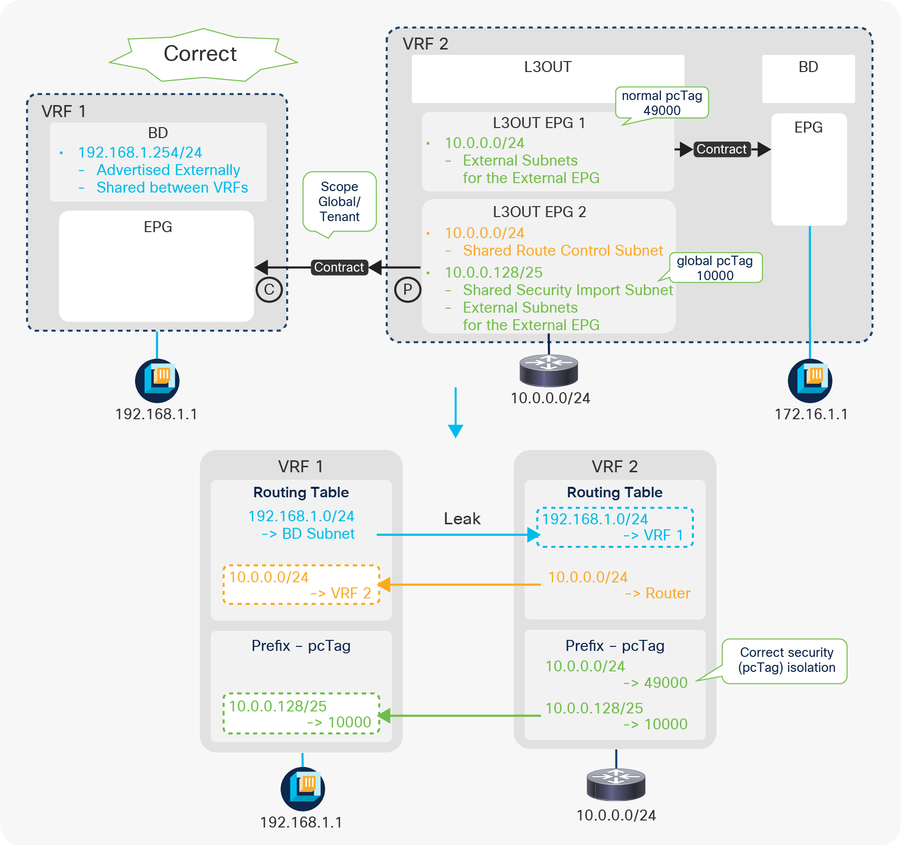
Shared L3Out advanced configuration 1 (a correct example)
In Figure 131, the configuration uses a different L3Out EPG for intra-VRF communication (10.0.0.0/24). Because of this, when a packet (source IP 10.0.0.1, destination IP 192.168.1.1) arrives from the L3Out in VRF 2, the source IP 10.0.0.1 is classified into the normal pcTag 49000 and will be dropped by the ingress provider VRF (VRF 2) since there is no route-leaking configuration for the normal pcTag (L3Out EPG 1). This ensures that only 10.0.0.128/25 will be allowed to go between VRFs.
Advanced configuration 2 (Shared L3Out with multiple VRF/BDs)
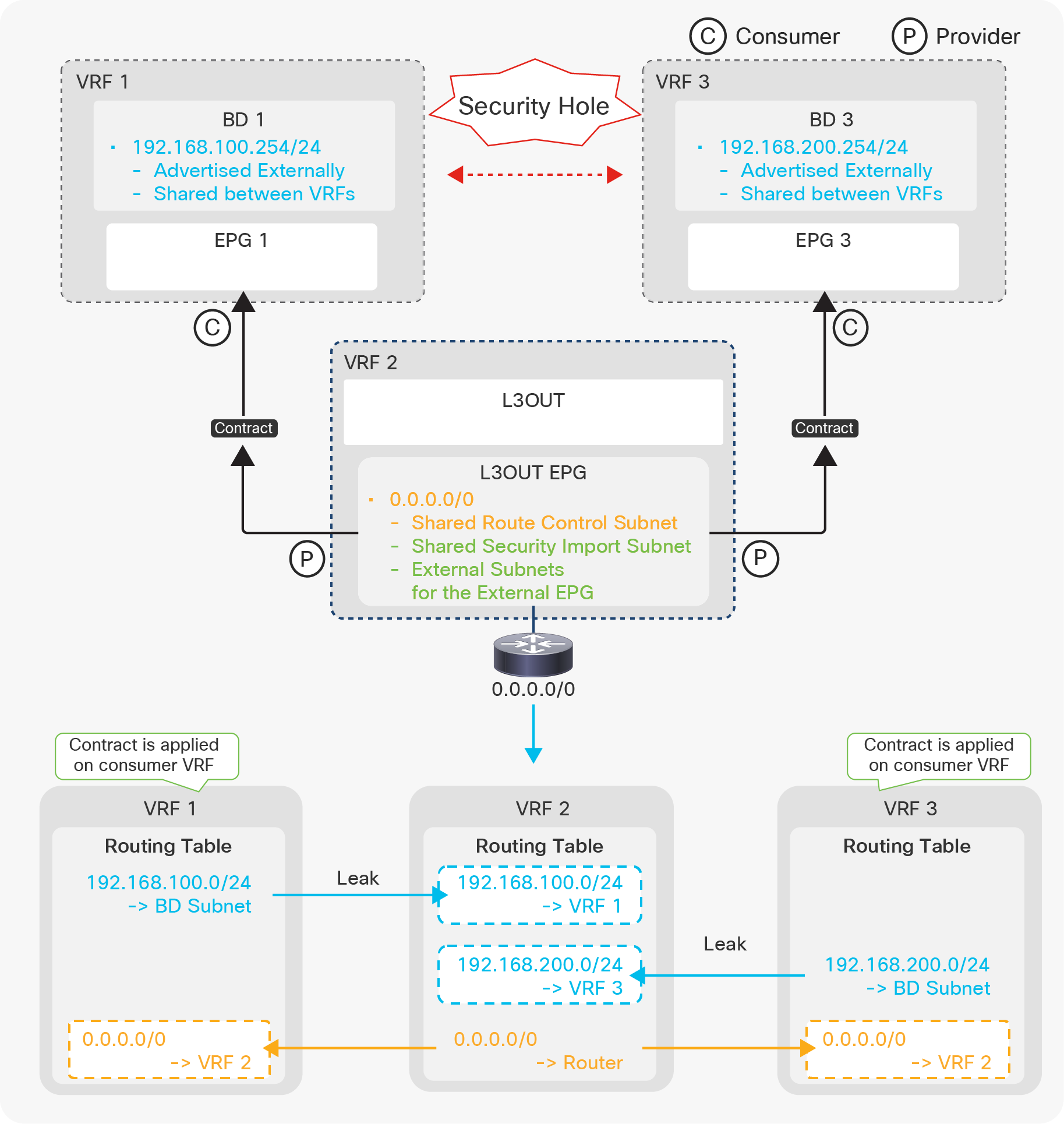
Shared L3Out advanced configuration 2 (Shared L3Out with multiple VRF/BDs)
Figure 132 illustrates a configuration where one L3Out (in VRF 2) is sharing (leaking) a default route to EPGs in VRF 1 and VRF 3. This configuration is valid. EPGs in VRF 1 and 3 can communicate with devices behind L3Out in VRF 2 based on the contract. However, users need to be aware of a security hole with this configuration in first-generation leaf switches. This configuration with first-generation leaf switches results in that EPG 1 in VRF 1 and EPG 3 in VRF 3 can also communicate with each other through VRF 2. In shared service (VRF route leaking), a contract is applied in a consumer VRF with a global pcTag shared by a provider VRF. This means, in this example, that a contract is applied on either VRF 1 or VRF 3. When EPG 1 in VRF 1 tries to talk to 192.168.200.1 (EPG 3 in VRF 3), it falls under the default route leaked by VRF 2, and a contract for the default route is applied. Hence, the packet is allowed on the ingress consumer VRF 1. After that, it just follows a routing table on each VRF in order to reach VRF 3 without being applied more contracts. To avoid this issue on first-generation leaf switches, the L3Out in VRF 2 should leak only unique routes that do not overlap with subnets in other VRFs.
On second-generation (or later) leaf switches, traffic from VRF 1 gets dropped on VRF 2 instead of getting forwarded to VRF 3 through VRF 2. However, when the ingress EPG and the shared L3Out are on the same leaf, traffic is sent out to the external device which may send the traffic back to ACI VRF 2. In such a case, the traffic is sent to VRF 3 if 0.0.0.0/0 is used for “External Subnets for the External EPG/Shared Security Import Subnet” on top of “Shared Route Control Subnet”. If non-0.0.0.0/0 subnets such as 0.0.0.0/1 and 128.0.0.0/1 are used for “External Subnets for the External EPG/Shared Security Import Subnet” while 0.0.0.0/0 is used only for “Shared Route Control Subnet”, the traffic is dropped when it’s sent back to ACI VRF 2.
Advanced configuration 3 (Shared L3Out with multiple VRF/L3Outs)
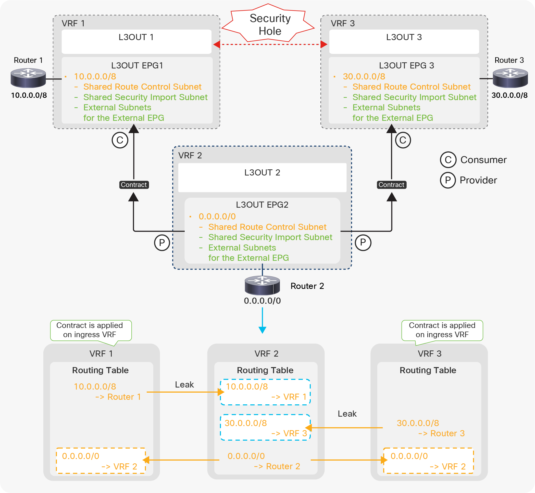
Shared L3Out advanced configuration 3 (Shared L3Out with multiple VRF/L3Outs)
Figure 133 illustrates a configuration where one L3Out (in VRF 2) is sharing (leaking) a default route to VRF 1 and VRF 3. In exchange, VRF 2 is receiving external routes (10.0.0.0/8, 30.0.0.0/8) from L3Outs in VRF 1 and 3. This configuration may allow traffic from L3Out 1 (VRF 1) to L3Out 3 (VRF 3) through VRF 2 regardless of leaf generations. On second-generation leaf switches, if the source L3Out (VRF) is on the same border leaf as the intermediate VRF 2, the traffic is sent out to Router 2 via L3Out 2 in VRF 2 instead of being reforwarded to VRF 3. For example, if L3Out 1 (VRF 1) and L3Out 2 (VRF 2) are on the same border leaf, traffic from 10.0.0.0/8 (L3Out 1) to 30.0.0.0/8 (L3Out 3) is sent out to Router 2 in VRF 2 instead of being reforwarded to L3Out 3 in VRF 3. This means that if all three L3Outs are on the same border leaf, this security hole can be prevented. In the case of three L3Outs being deployed on different leaf switches, VRF 2 should leak only unique routes that do not overlap with other VRFs. This issue will be fixed through the following:
CSCvt06173 ACI: Shared L3Outs allow traffic through the intermediate VRF
Advanced configuration 4 (Shared L3Out with unintended leak)
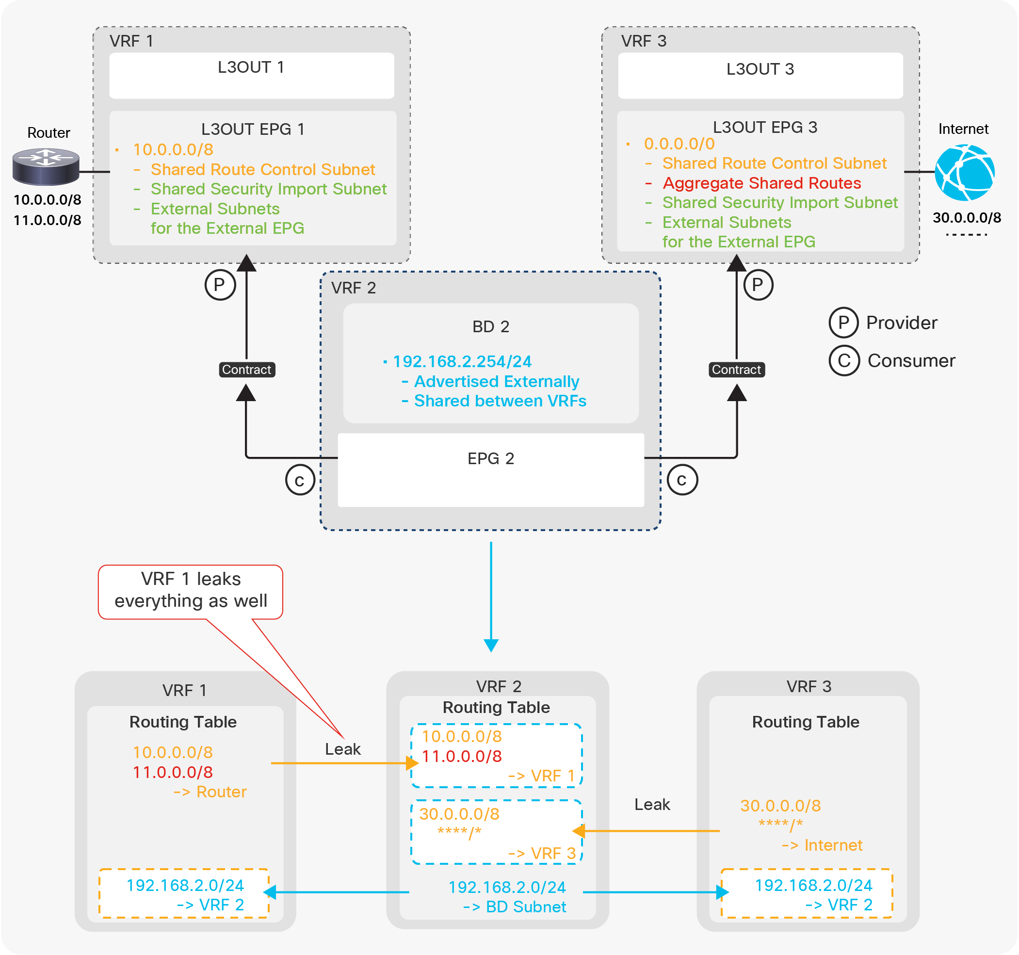
Shared L3Out advanced configuration 4 (Shared L3Out with unintended leak)
Figure 134 illustrates a configuration where VRF 2 is receiving (shared/leaked) routes from multiple VRFs. The intention is L3Out 1 (VRF 1) to leak only 10.0.0.0/8 without 11.0.0.0/8, and L3Out 3 (VRF 3) to leak all routes to VRF 2. In this configuration, however, not only 10.0.0.0/8 but also all routes from L3Out 1 (VRF 1) are leaked to VRF 2. This is because VRF 2 only checks the prefix when it imports routes from other VRFs via MP-BGP VPNv4. It does not check its source VRF, which is identified by a Route-Target (RT) as mentioned in the “Infra MP-BGP” section. Hence, in this particular example, all routes from any VRFs are subject to be leaked (imported via MP-BGP) to VRF 2 due to Aggregate Shared Routes in L3Out 3. The same thing occurs if L3Out 3 is configured with Shared Route Control Subnet for 11.0.0.0/8 explicitly instead of the aggregate option. This means that the shared L3Out configuration in each VRF should specify only its own unique external routes without overlapping with other VRFs. This limitation was resolved in ACI 5.0(1k) as a result of the following enhancement:
CSCvi20535 ACI: Need VRF awareness in Shared Route Control scope for Shared L3Outs
Bidirectional forwarding detection (BFD) on L3Out interfaces was introduced in APIC Release 1.2(2). See the APIC Layer 3 Networking Configuration Guide for BFD on other components, such as ISIS between leaf and spine switches, OSPF, and static routes between spines and IPN devices, etc.
● BFD on L3Out is supported only on routed interface, subinterface, and SVI. It is not supported on loopback interfaces since there is no multihop BFD in ACI yet.
● BFD for BGP prefix peers (dynamic neighbors) is not supported.
● BFD subinterface optimization can be enabled only on the Interface BFD Policy, but not on the Global BFD Policy. When BFD subinterface optimization is enabled on one subinterface, it will be activated for all of the subinterfaces on the same physical interface.
There is just one checkbox in each L3Out to enable and establish a BFD session if no customization is required. As mentioned in the previous sections for each of the L3Out routing protocols, Figure 135 shows the checkbox to enable BFD, which is disabled by default.
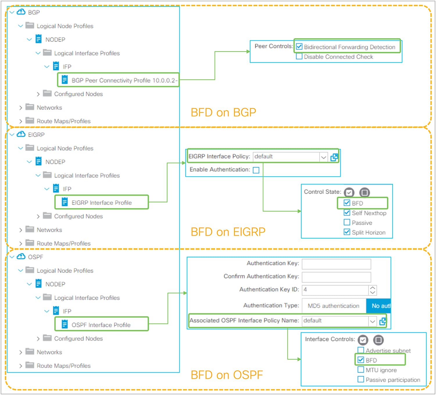
Enable BFD on L3Out routing protocols in the GUI (APIC Release 3.2)
When BFD is enabled without any customization, the BFD parameters will be derived from a default BFD policy located under “Fabric > Access Policies > Policies > Switch > BFD > BFD IPv4/v6 > default”. See the next section for how to customize BFD parameters.
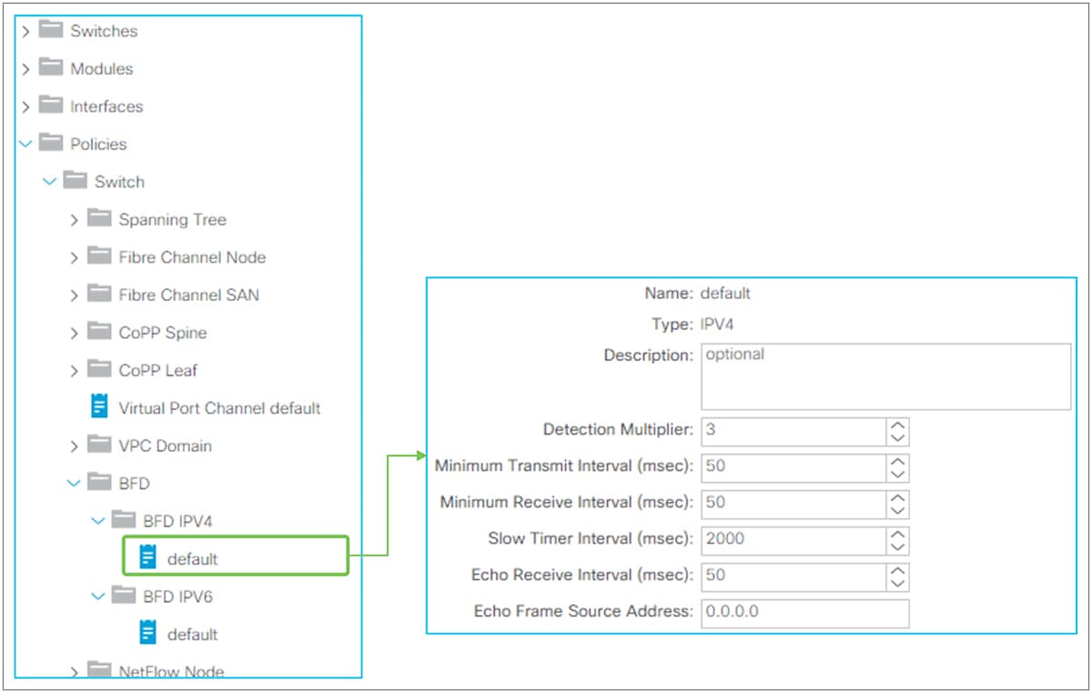
Global BFD parameters in the GUI (APIC Release 3.2)
A default global BFD policy located under “Fabric > Access Policies > Policies > Switch > BFD > BFD IPv4/v6 > default” contains the BFD parameters to be used on any switches in the ACI fabric. Users can also create a nondefault BFD policy and apply it to a specific switch via Switch Policy Group and Switch Profile under “Fabric > Access Policies > Switches”.
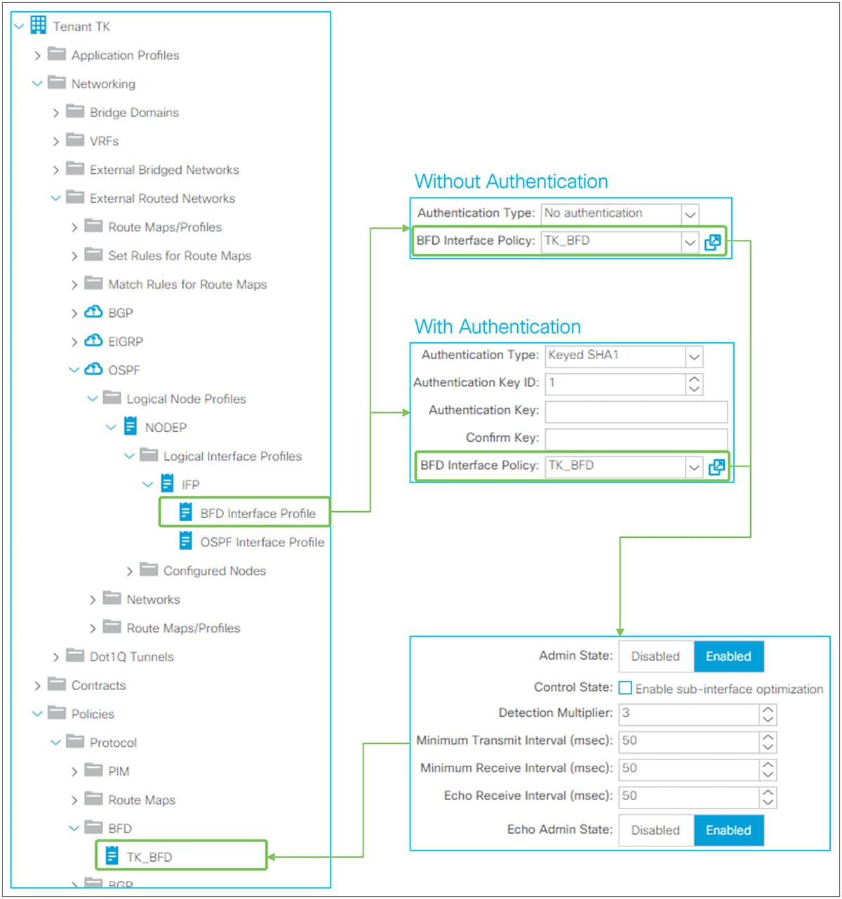
Interface BFD parameters in the GUI (APIC Release 3.2)
Users can override the BFD parameters from a switch-level global BFD policy via an interface-level BFD policy by creating BFD Interface Profile under Logical Interface Profile. The interface-level BFD policy is located under “Tenant > Policies > Protocol > BFD”.
| New or Revised Content |
Updated section |
Date |
| Added a note to call out that routes learned via OSPF inside a BGPL3Out are not distributed to other switches via MP-BGP. |
L3Out BGP > Limitations and guidelines |
February 28, 2023 |
| Added a corner case for 2nd generation switches when the ingress VRF and shared VRF are on the same leaf |
L3Out Shared Service (VRF route leaking) > Advanced shared L3Out configuration options > Advanced configuration 2 (Shared L3Out with multiple VRF/BDs) |
January 6, 2023 |