FlashStack with Cisco UCS X-Series and Cisco Intersight
Available Languages
Bias-Free Language
The documentation set for this product strives to use bias-free language. For the purposes of this documentation set, bias-free is defined as language that does not imply discrimination based on age, disability, gender, racial identity, ethnic identity, sexual orientation, socioeconomic status, and intersectionality. Exceptions may be present in the documentation due to language that is hardcoded in the user interfaces of the product software, language used based on RFP documentation, or language that is used by a referenced third-party product. Learn more about how Cisco is using Inclusive Language.
The FlashStack solution is a validated, converged infrastructure developed jointly by Cisco and Pure Storage. The solution offers a predesigned data center architecture that incorporates computing, storage, and network design best practices to reduce IT risk by validating the architecture and helping ensure compatibility among the components. The FlashStack solution is successful because of its ability to evolve and incorporate both technology and product innovations in the areas of management, compute, storage, and networking. This document covers the design details of incorporating the Cisco Unified Computing System™ (Cisco UCS®) X-Series modular platform into the FlashStack and its ability to manage and orchestrate FlashStack components from the cloud using the Cisco Intersight™. Some of the most important advantages of integrating the Cisco UCS X-Series into the FlashStack infrastructure follow:
● Simpler and programmable infrastructure: Infrastructure as a code delivered through an open application programming interface (API)
● Power and cooling innovations: Higher-power headroom and lower energy loss because of a 54V DC power delivery to the chassis
● Better airflow: Midplane free design with fewer barriers, thus lower impedance
● Fabric innovations: PCIe/Compute Express Link (CXL) topology for heterogeneous compute and memory composability
● Innovative cloud operations: Continuous feature delivery and no need for management virtual machines
● Built for investment protections: Design-ready for future technologies such as liquid-cooling and high-wattage CPUs; CXL-ready
In addition to the compute-specific hardware and software innovations, integration of the Cisco Intersight cloud platform with VMware vCenter and Pure Storage FlashArray delivers monitoring, orchestration, and workload optimization capabilities for different layers (virtualization and storage) of the FlashStack solution. The modular nature of the Cisco Intersight platform also provides an easy upgrade path to additional services such as workload optimization and Kubernetes.
If you are interested in understanding FlashStack design and deployment details, including configuration of various elements of design and associated best practices, please refer to Cisco Validated Designs for FlashStack at: https://www.cisco.com/c/en/us/solutions/design-zone/data-center-design-guides/data-center-design-guides-all.html#FlashStack.
Introduction
The Cisco UCS X-Series is a new modular compute system configured and managed from the cloud. It is designed to meet the needs of modern applications and improve operational efficiency, agility, and scale through an adaptable, future-ready, modular design. The Cisco Intersight platform software-as-a-service (SaaS) infrastructure lifecycle management platform delivers simplified configuration, deployment, maintenance, and support.
Powered by the Cisco Intersight cloud operations platform, the Cisco UCS X-Series enables the next-generation cloud-operated FlashStack infrastructure that not only simplifies the datacenter management but also allows the infrastructure to adapt to unpredictable needs of the modern applications as well as traditional workloads. With the Cisco Intersight platform, you get all the benefits of SaaS delivery and the full lifecycle management of Cisco Intersight connected, distributed servers and integrated Pure Storage FlashArray across data centers, remote sites, branch offices, and edge environments.
Audience
The intended audience of this document includes but is not limited to IT architects, sales engineers, field consultants, professional services, IT managers, partner engineering, and customers who want to take advantage of an infrastructure built to deliver IT efficiency and enable IT innovation.
Purpose of this document
This document provides design guidance around incorporating the Cisco Intersight software-managed Cisco UCS X-Series platform within the FlashStack solution. The document introduces various design elements and addresses various considerations and best practices for a successful deployment. It also highlights the design and product requirements for integrating virtualization and storage systems with the Cisco Intersight platform to deliver a true cloud-based integrated approach to infrastructure management.
What’s new in this release?
The following design elements distinguish this version of FlashStack software from previous models:
● Integration of the Cisco UCS X-Series
● Management of the Cisco UCS X-Series from the cloud using the Cisco Intersight platform
● Integration of the Cisco Intersight platform with Pure Storage FlashArray for storage monitoring and orchestration
● Integration of the Cisco Intersight software with VMware vCenter for interacting with, monitoring, and orchestrating the virtual environment
Solution summary
The FlashStack solution with the Cisco UCS X-Series and Cisco Intersight software offers the following critical benefits:
● Simplified cloud-based management of the solution components
● Hybrid cloud-ready policy-directed modular design
● Highly available and scalable platform with flexible architecture that supports various deployment models
● Cooperative support model and Cisco® solution support
● Architecture that is easy to deploy, consume, and manage, saving time and resources required to research, procure, and integrate off-the-shelf components
● Support for component monitoring, solution orchestration, and workload optimization
Like all other FlashStack solution designs, FlashStack with Cisco UCS X-Series and Cisco Intersight software is configurable according to the demand and usage. You can purchase exactly the infrastructure you need for your current application requirements and then can scale up by adding more resources to the FlashStack system or scale out by adding more FlashStack instances. if you move the management from the fabric interconnects into the cloud, the solution can respond to speed and scale of your deployments with a constant stream of new capabilities delivered from the Cisco Intersight SaaS model at cloud scale.
FlashStack Virtual Server Infrastructure overview
Many enterprises today are seeking pre-engineered solutions that standardize data center infrastructure, offering organizations operational efficiency, agility, and scale to address cloud and bimodal IT and their business. Their challenge is complexity, diverse application support, efficiency, and risk. FlashStack (Figure 1) addresses all the challenges with these features:
● Stateless architecture, providing the capability to expand and adapt to new business requirements
● Reduced complexity, automatable infrastructure, and easily deployed resources
● Robust components capable of supporting high-performance and high-bandwidth virtualized applications
● Efficiency through optimization of network bandwidth and inline storage compression with deduplication
● Risk reduction at each level of the design with resiliency built into each touch point
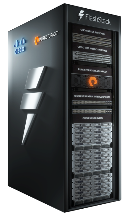
FlashStack rack
Cisco and Pure Storage have partnered to deliver several Cisco Validated Designs, which use best-in-class storage, server, and network components to serve as the foundation for virtualized workloads, enabling efficient architectural designs that you can deploy quickly and confidently.
FlashStack components
FlashStack architecture is built using the following infrastructure components for compute, network, and storage (Figure 2):
● Cisco Unified Computing System (Cisco UCS)
● Cisco Nexus® switches
● Cisco MDS 9000 switches
● Pure Storage FlashArray
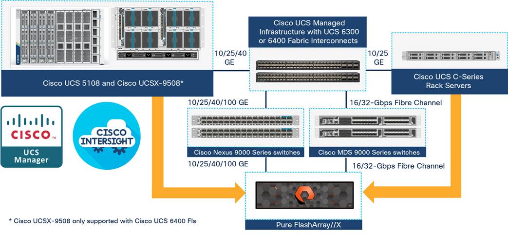
FlashStack components
All the FlashStack components are integrated, so you can deploy the solution quickly and economically while eliminating many of the risks associated with researching, designing, building, and deploying similar solutions from the foundation. One of the main benefits of FlashStack is its ability to maintain consistency at scale. Each of the component families shown in Figure 2 (Cisco UCS, Cisco Nexus, Cisco MDS, and Pure Storage FlashArray systems) offers platform and resource options to scale up or scale out the infrastructure while supporting the same features and functions.
The FlashStack solution with Cisco UCS X-Series and Cisco Intersight software uses following hardware components:
● Cisco UCS X9508 chassis with any number of Cisco UCS X210c M6 compute nodes
● Cisco fourth-generation 6454 fabric interconnects to support 25- and 100-GE connectivity from various components
● High-speed Cisco NXOS-based Nexus 93180YC-FX3 switching design to support up to 100-GE connectivity
● Pure Storage FlashArray//X50 R3 with high-speed Ethernet or Fibre Channel connectivity
The software components consist of:
● Cisco Intersight platform to deploy, maintain, and support the FlashStack components
● Cisco Intersight Assist virtual appliance to help connect the Pure Storage FlashArray and VMware vCenter with the Cisco Intersight platform
● VMware vCenter to set up and manage the virtual infrastructure as well as integration of the virtual environment with Cisco Intersight software
The next section outlines these critical product highlights and features.
Cisco Unified Computing System X-Series
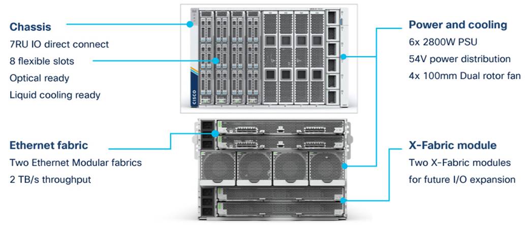
The Cisco UCS X-Series modular system is designed to take the current generation of the Cisco UCS platform to the next level with its design that will support future innovations and management in the cloud (Figure 3). Decoupling and moving platform management to the cloud allows the Cisco UCS platform to respond to your feature and scalability requirements much faster and more efficiently. Cisco UCS X-Series state-of-the-art hardware simplifies the datacenter design by providing flexible server options. A single server type that supports a broader range of workloads results in fewer different datacenter products to manage and maintain. The Cisco Intersight cloud management platform manages the Cisco UCS X-Series as well as integrating with third-party devices. These devices include VMware vCenter and Pure Storage to provide visibility, optimization, and orchestration from a single platform, thereby enhancing agility and deployment consistency.
Cisco UCSX-9508 chassis
The following sections address various components of the Cisco UCS X-Series.
Cisco UCSX-9508 chassis
The Cisco UCS X-Series chassis is engineered to be adaptable and flexible. As shown in Figure 4, the only midplane of the UCSX-9508 chassis is just a power-distribution midplane. This innovative design provides fewer obstructions for better airflow. For I/O connectivity, vertically oriented compute nodes intersect with horizontally oriented fabric modules, allowing the chassis to support future fabric innovations. Superior packaging of the Cisco UCSX-9508 chassis enables larger compute nodes, thereby providing more space for actual compute components such as memory, GPU, drives, and accelerators. Improved airflow through the chassis enables support for higher-power components, and more space allows for future thermal solutions (such as liquid cooling) without limitations.
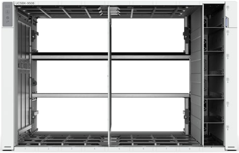
Cisco UCS X9508 chassis – only power distribution midplane
The Cisco UCSX-9508 7-rack-unit (7RU) chassis has 8 flexible slots. These slots can house a combination of compute nodes and a pool of future I/O resources that may include GPU accelerators, disk storage, and nonvolatile memory (NVM). At the top rear of the chassis are two intelligent fabric modules (IFM) that connect the chassis to upstream Cisco UCS 6400 Series fabric interconnects. At the bottom rear of the chassis are slots ready to house future X-Fabric modules that can flexibly connect the compute nodes with I/O devices. Six 2800W power supply units (PSUs) provide 54V DC power to the chassis with N, N+1, and N+N redundancy. A higher voltage allows efficient power delivery with less copper and reduced power loss. Efficient, 100-mm, dual counter-rotating fans deliver industry-leading airflow and power efficiency, and optimized thermal algorithms enable different cooling modes to best support your environment.
Cisco UCSX 9108-25G intelligent fabric modules
For the Cisco UCSX-9508 chassis, a pair of Cisco UCS 9108-25G IFMs provide network connectivity. Like the fabric extenders used in the Cisco UCS 5108 Blade Server chassis, these modules carry all network traffic to a pair of Cisco UCS 6400 Series fabric interconnects. IFM also hosts a chassis management controller (CMC). High-speed PCIe-based fabric topology provides extreme flexibility compared to a combination of serial-attached SCSI (SAS), Serial Advanced Technology Attachment (SATA), or Fibre Channel. In contrast to systems with fixed networking components, the design of the Cisco UCSX-9508 enables easy upgrades to new networking technologies as they emerge, making it straightforward to accommodate new network speeds or technologies in the future.
Each IFM supports eight 25-Gb uplink ports for connecting the Cisco UCSX-9508 chassis to the fabric interconnects and thirty-two 25-Gb server ports for the 8 compute nodes. The IFM server ports can provide up to 200 Gbps of unified fabric connectivity per compute node across the two IFMs. The uplink ports connect the chassis to a Cisco UCS fabric interconnect to provide up to 400-Gbps connectivity across the two IFMs. The unified fabric carries management, virtual-machine, and Fibre Channel over Ethernet (FCoE) traffic to the fabric interconnects, where management traffic is routed to the Cisco Intersight cloud operations platform. FCoE traffic is forwarded to the native Fibre Channel interfaces through unified ports on the fabric interconnect (to Cisco MDS switches), and virtual-machine Ethernet traffic is forwarded upstream to the data center network (by Cisco Nexus switches).
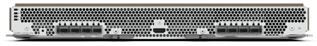
Cisco UCS 9108-25G IFM
Cisco UCS X210c M6 server
The Cisco UCS X9508 chassis is designed to host up to 8 Cisco UCS X210c M6 servers. Figure 6 shows the hardware details of the Cisco UCS X210c M6 compute node.
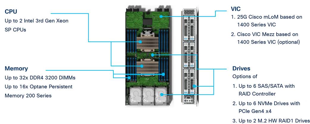
Cisco UCS X210c M6 compute node
Features of the Cisco UCS X210c M6 follow:
● CPU: The solution uses up to two third-generation Intel Xeon scalable processors with up to 40 cores per processor and a 1.5-MB Level 3 cache per core.
● Memory: The solution uses up to thirty-two 256-GB DDR4-3200 (DIMMs) for a maximum of 8 TB of main memory. You can configure the compute node for up to sixteen 512-GB Intel Optane persistent memory DIMMs for a maximum of 12 TB of memory.
● Disk storage: You can configure up to 6 SAS or SATA drives with an internal (RAID) controller or up to 6 nonvolatile memory express (NVMe) drives. You can add 2 M.2 memory cards to the compute node with RAID 1 mirroring.
● Virtual interface card: You can install up to 2 virtual interface cards, including a Cisco UCS Virtual Interface Card (VIC) modular LOM card (mLOM) 14425, and a mezzanine Cisco VIC 14825 in a compute node.
● Security: The server supports an optional trusted platform module (TPM). Additional security features include a secure a boot field-programmable gate array (FPGA) and ACT2 anti-counterfeit provisions.
Cisco UCS VICs
Cisco UCS X210c M6 compute nodes support the following two Cisco fourth-generation VIC cards:
Cisco VIC 14425
Cisco VIC 14425 fits the mLOM slot in the Cisco X210c compute node and enables up to 50 Gbps of unified fabric connectivity to each of the chassis IFMs for a total of 100 Gbps of connectivity per server (Figure 7). Cisco VIC 14425 connectivity to the IFM and up to the fabric interconnects is delivered through four 25-Gbps connections that are configured automatically as two 50-Gbps port channels. Cisco VIC 14425 supports 256 virtual interfaces (both Fibre Channel and Ethernet) along with the latest networking innovations such as NVMe over Fabric over Remote Direct Memory Access (RDMA), RDMA over Converged Infrastructure (RoCEv2), Virtual Extensible VLAN gateway/Network Virtualization using Generic Routing Encapsulation (VxLAN/NVGRE) offload, etc.
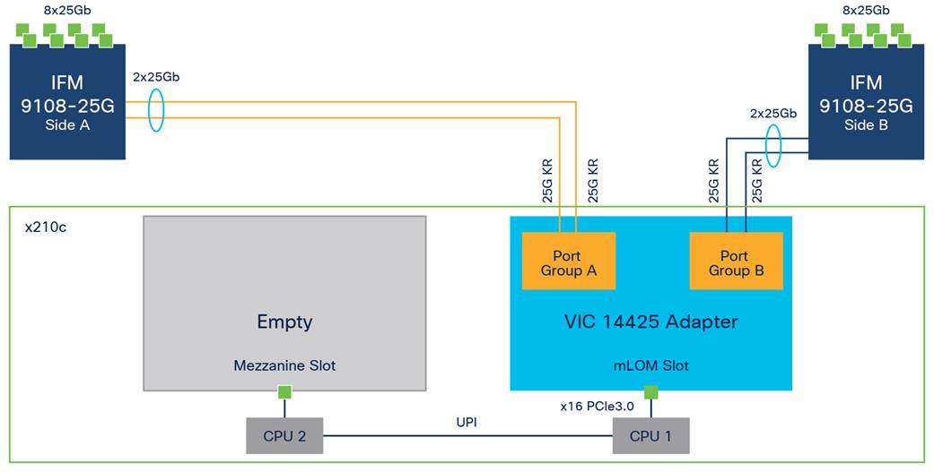
Single Cisco VIC 14425 in Cisco UCS X210c M6
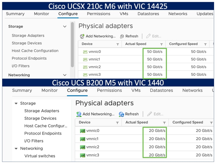
The connections between the fourth-generation Cisco VIC (Cisco UCS VIC 1440) in the Cisco UCS B200 blades and the I/O modules in the Cisco UCS VIC 5108 chassis comprise multiple 10-Gbps KR lanes. The same connections between Cisco VIC 14425 and IFM in the Cisco UCS X-Series comprise multiple 25-Gbps KR lanes, resulting in 2.5 times better connectivity in Cisco UCS X210c M6 compute nodes. The following screenshot shows the network interface speed comparison for VMware ESXi installed on the Cisco UCS B200 M5 with a VIC 1440 and Cisco UCSX 210c M6 with a VIC 14425.
Cisco VIC 14825
The optional Cisco VIC 14825 fits the mezzanine slot on the server. A bridge card (part number UCSX-V4-BRIDGE) extends the two 50 Gbps of network connections of this VIC up to the mLOM slot and out through the IFM connectors of the mLOM, bringing the total bandwidth to 100 Gbps per fabric for a total bandwidth of 200 Gbps per server (refer to Figure 8).
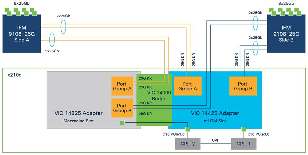
Cisco VIC 14425 and 14825 in Cisco UCS X210c M6
Cisco UCS 6400 fabric interconnects
The Cisco UCS fabric interconnects provide a single point for connectivity and management for the entire Cisco UCS system. Typically deployed as an active-active pair, the fabric interconnects of the system integrate all components into a single, highly available management domain that Cisco UCS Manager or the Cisco Intersight platform manages. Cisco UCS fabric interconnects provide a single unified fabric for the system, with low-latency, lossless, cut-through switching that supports LAN, storage-area network (SAN), and management traffic using a single set of cables (refer to Figure 9.

Cisco UCS 6454 fabric interconnect
The Cisco UCS 6454 used in the current design is a 54-port fabric interconnect. This 1RU device includes twenty-eight 10-/25-GE ports, four 1-/10-/25-GE ports, six 40-/100-GE uplink ports, and sixteen unified ports that can support 10-/25-GE or 8-/16-/32-Gbps Fibre Channel, depending on the Small Form-Factor Pluggable (SFP) adapter.
Note: For supporting the Cisco UCS X-Series, you must configure the fabric interconnects in Cisco Intersight managed mode. This option replaces the local management with Cisco Intersight cloud (or appliance)-based management.
Cisco Intersight platform
The SaaS Cisco Intersight infrastructure lifecycle management platform delivers simplified configuration, deployment, maintenance, and support. It is designed to be modular, so you can adopt services based on your individual requirements. The platform significantly simplifies IT operations by bridging applications with infrastructure, providing visibility and management from bare-metal servers and hypervisors to serverless applications, thereby reducing costs and mitigating risk. This unified SaaS platform uses a unified open application programming interface (API) design that natively integrates with the third-party platforms and tools. Figure 10 shows an overview of the platform.
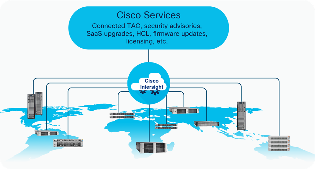
Cisco Intersight overview
The main benefits of Cisco Intersight infrastructure services follow:
● Simplify daily operations by automating many daily manual tasks.
● Combine the convenience of a SaaS platform with the capability to connect from anywhere and manage infrastructure through a browser or mobile app.
● Stay ahead of problems and accelerate trouble resolution through advanced support capabilities.
● Gain global visibility of infrastructure health and status along with advanced management and support capabilities.
● Upgrade to add workload optimization and Kubernetes services when needed.
Cisco Intersight virtual appliance and private virtual appliance
In addition to the SaaS deployment model running on Intersight.com, you can purchase on-premises options separately. The Cisco Intersight virtual appliance and Cisco Intersight private virtual appliance are available for organizations that have additional data locality or security requirements for managing systems. The Cisco Intersight virtual appliance delivers the management features of the Cisco Intersight platform in an easy-to-deploy VMware Open Virtualization Appliance (OVA) or Microsoft Hyper-V Server virtual machine that allows you to control the system details that leave your premises. The Cisco Intersight private virtual appliance is provided in a form factor designed specifically for users who operate in disconnected (air gap) environments. The private virtual appliance requires no connection to public networks or to Cisco network.
Cisco Intersight Assist
Cisco Intersight Assist helps you add endpoint devices to the Cisco Intersight platform. A datacenter could have multiple devices that do not connect directly with the platform. Any device that the Cisco Intersight platform supports but does not connect with directly must have a connection mechanism, and Cisco Intersight Assist provides it. In FlashStack, VMware vCenter and Pure Storage FlashArray connect to the Intersight platform with the help of the Cisco Intersight Assist virtual machine.
Cisco Intersight Assist is available within the Cisco Intersight virtual appliance, which is distributed as a deployable virtual machine contained within an OVA file format. Later sections in this paper have more details about the Cisco Intersight Assist virtual-machine deployment configuration.
Licensing requirements
The Cisco Intersight platform uses a subscription-based license with multiple tiers. You can purchase a subscription duration of 1, 3, or 5 years and choose the required Cisco UCS server volume tier for the selected subscription duration. Each Cisco endpoint automatically includes a Cisco Intersight Base license at no additional cost when you access the Cisco Intersight portal and claim a device. You can purchase any of the following higher-tier Cisco Intersight licenses using the Cisco ordering tool:
● Cisco Intersight Essentials: Essentials includes all the functions of the Base license plus additional features, including Cisco UCS Central software and Cisco Integrated Management Controller (IMC) supervisor entitlement, policy-based configuration with server profiles, firmware management, and evaluation of compatibility with the Cisco Hardware Compatibility List (HCL).
● Cisco Intersight Advantage: Advantage offers all the features and functions of the Base and Essentials tiers. It also includes storage widgets and cross-domain inventory correlation across compute, storage, and virtual environments (VMware ESXi). OS installation for supported Cisco UCS platforms is also included.
● Cisco Intersight Premier: In addition to the functions provided in the Advantage tier, Premier includes full subscription entitlement for Cisco UCS Director, providing orchestration across Cisco UCS and third-party systems.
Servers in the Cisco Intersight managed mode require at least the Essentials license. For more information about the features provided in the various licensing tiers, please visit: https://intersight.com/help/getting_started#licensing_requirements.
View the current Cisco Intersight Infrastructure Service licensing.
Cisco Nexus switching fabric
The Cisco Nexus 9000 Series switches offer both modular and fixed 1-/10-/25-/40-/100-GE switch configurations with scalability up to 60 Tbps of nonblocking performance with less than 5-microsecond latency, wire-speed VXLAN gateway, bridging, and routing support (refer to Figure 11).
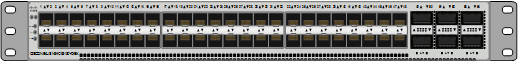
Nexus 93180YC-FX3 switch
The Nexus 9000 switch featured in this design is the Nexus 93180YC-FX3 configured in NX-OS standalone mode. NX-OS is a datacenter operating system designed for performance, resiliency, scalability, manageability, and programmability at its foundation. It provides a robust and comprehensive feature set that meets the demanding requirements of virtualization and automation in present and future datacenters.
The 1RU Cisco Nexus 93180YC-FX3 switch supports 3.6 Tbps of bandwidth and 1.2 billion packets per second. The 48 downlink ports on the 93180YC-FX3 can support 1-/10-/25-GE, offering deployment flexibility and investment protection. You can configure the 6 uplink ports can as 40- or 100-GE, offering flexible migration options.
Cisco MDS
The Cisco MDS 9132T 32G multilayer fabric switch is the next generation of the highly reliable, flexible, and low-cost Cisco MDS 9100 Series switches (Figure 12). It combines high performance with exceptional flexibility and cost-effectiveness. This powerful, compact 1RU switch scales from 8 to 32 line-rate 32-Gbps Fibre Channel ports.
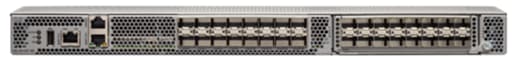
Cisco MDS 9132T
The Cisco MDS 9132T delivers advanced storage networking features and functions with ease of management and compatibility with the entire Cisco MDS 9000 Family portfolio for reliable end-to-end connectivity. This switch also offers state-of-the-art SAN analytics and telemetry capabilities that are built into this next-generation hardware platform. This new state-of-the-art technology couples the next-generation port application-specific integrated circuit (ASIC) with a fully dedicated network processing unit designed to complete analytics calculations in real time. The telemetry data extracted from the inspection of the frame headers are calculated on board (within the switch) and, using an industry-leading open format, can be streamed to any analytics-visualization platform. This switch also includes a dedicated 10/100/1000BASE-T telemetry port to maximize data delivery to any telemetry receiver, including Cisco Data Center Network Manager.
Cisco Data Center Network Manager SAN
You can use the Cisco Data Center Network Manager (DCNM)-SAN to monitor, configure, and analyze Cisco 32-Gbps Fibre Channel fabrics and show information about the Cisco Nexus switching fabric. Cisco DCNM-SAN is deployed as a virtual appliance from an OVA and is managed through a web browser. When you add the Cisco MDS and Nexus switches with the appropriate credentials and licensing, you can begin monitoring of the SAN and Ethernet fabrics. Additionally, you can add, modify, and delete virtual SANs (VSANs), device aliases, zones, and zonesets using the DCNM point-and-click interface. You also can use Cisco Data Center Device Manager to configure the Cisco MDS switches. You can add SAN analytics to Cisco MDS switches to gain insights into the fabric monitoring, analyzing, identifying, and troubleshooting performance problems.
Cisco DCNM integration with Cisco Intersight platform
The Cisco Network Insights Base (Cisco NI Base) application provides Cisco Technical Assistance Center (TAC) Assist functions that are useful when working with the center. It provides a way for Cisco customers to collect technical support across multiple devices and upload those tech supports to Cisco Cloud. The Cisco NI Base app collects the CPU, device name, device product ID, serial number, version, memory, device type, and disk-usage information for the nodes in the fabric. The Cisco NI Base application is connected to the Cisco Intersight cloud portal through a device connector that is embedded in the management controller of the Cisco DCNM platform. The device connector provides a secure way for connected Cisco DCNM to send and receive information from the Cisco Intersight portal by using a secure Internet connection.
Pure Storage FlashArray//X
The Pure Storage FlashArray Family delivers software-defined all-flash power and reliability for businesses of every size. FlashArray is all-flash enterprise storage that is up to 10X faster, space and power efficient, reliable, and far simpler than other available solutions. At the top of the FlashArray line is FlashArray//X—the first mainstream, 100-percent NVMe, enterprise-class all-flash array. //X represents a higher performance tier for mission-critical databases, top-of-rack flash deployments, and tier 1 application consolidation. //X, at 1PB in 3RU, hundred-microsecond range latency, and GBs of bandwidth, delivers an unprecedented level of performance density. FlashArray//X is ideal for cost-effective consolidation of everything on flash, including accelerating a single database, scaling virtual desktop environments, or powering an all-flash cloud.
Purity for FlashArray
Purity//FlashArray implements advanced data reduction, storage management, and flash management features, enabling your organization to enjoy tier 1 data services for all workloads. Purity software provides proven 99.9999-percent availability over 2 years, completely nondisruptive operations, 2X better data reduction, and the power and efficiency of DirectFlash. Purity also includes enterprise-grade data security, comprehensive data-protection options, and complete business continuity with an ActiveCluster multi-site stretch cluster. All these features are included with every Pure Storage array.
FlashArray//X R3 specification
Table 1 covers both capacity and physical aspects of various FlashArray systems.
Table 1. FlashArray//X R3 Specifications
|
|
Capacity |
Physical |
| //X10 |
Up to 73 TB/66.2 TiB (tebibyte) effective capacity** Up to 22 TB/19.2 TiB raw capacity |
3RU; 640–845 watts (nominal – peak) 95 lb (43.1 kg) fully loaded; 5.12 x 18.94 x 29.72 in. |
| //X20 |
Up to 314 TB/285.4 TiB effective capacity** Up to 94 TB/88 TiB raw capacity† |
3RU; 741–973 watts (nominal – peak) 95 lb (43.1 kg) fully loaded; 5.12 x 18.94 x 29.72 in. |
| //X50 |
Up to 663 TB/602.9 TiB effective capacity** Up to 185 TB/171 TiB raw capacity† |
3RU; 868–1114 watts (nominal – peak) 95 lb (43.1 kg) fully loaded; 5.12 x 18.94 x 29.72 in. |
| //X70 |
Up to 2286 TB/2078.9 TiB effective capacity** Up to 622 TB/544.2 TiB raw capacity† |
3RU; 1084–1344 watts (nominal – peak) 97 lb (44.0 kg) fully loaded; 5.12 x 18.94 x 29.72 in. |
| //X90 |
Up to 3.3 PB/3003.1 TiB effective capacity** Up to 878 TB/768.3 TiB raw capacity† |
3–6RU; 1160–1446 watts (nominal – peak) 97 lb (44 kg) fully loaded; 5.12 x 18.94 x 29.72 in. |
| DirectFlash Shelf |
Up to 1.9 PB effective capacity** Up to 512 TB/448.2 TiB raw capacity |
3RU; 460–500 watts (nominal – peak) 87.7 lb (39.8kg) fully loaded; 5.12 x 18.94 x 29.72 in. |
Table 2 covers various connectivity options using both onboard and host I/O cards.
Table 2. FlashArray //X Connectivity
| Onboard ports (per controller) |
Host I/O cards (3 slots/controller) |
|
| Two 1-/10-/25-GE |
2-port 10GBASE-T Ethernet |
2-port 25-/50-/100-Gb NVMe/RoCE |
| Two 1-/10-/25-GE replication |
2-port 1/10/25 GE |
2-port 16-/32-Gb Fibre Channel (NVMeoF Ready) |
| Two 1-Gb management ports |
2-port 40 GE |
4-port 16-/32-Gb Fibre Channel (NVMeoF Ready) |
** Effective capacity assumes high availability, RAID, and metadata overhead, GB-to-GiB conversion, and includes the benefit of data reduction with always-on inline deduplication, compression, and pattern removal. Average data reduction is calculated at 5-to-1 and does not include thin provisioning.
† Array accepts Pure Storage DirectFlash Shelf and/or Pure.
Evergreen storage
You can deploy storage once and enjoy a subscription to continuous innovation with a Pure Storage Evergreen Storage ownership model to expand and improve performance, capacity, density, and/or features for 10 years or more without downtime, performance impact, or data migrations (Figure 13).
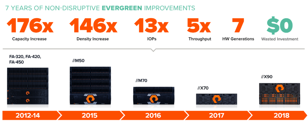
Pure Storage Evergreen storage
VMware vSphere 7.0
VMware vSphere is a virtualization platform for holistically managing large collections of infrastructures (resources - CPUs, storage, and networking) as a seamless, versatile, and dynamic operating environment. Unlike traditional operating systems that manage an individual machine, VMware vSphere aggregates the infrastructure of an entire data center to create a single powerhouse with resources that you can allocate quickly and dynamically to any application in need.
vSphere 7.0 brings several improvements and simplifications including, but not limited to:
● Fully featured vSphere Client (HTML5): The Flash-based vSphere Web Client that has been deprecated and is no longer available
● Improved Distributed Resource Scheduler (DRS): A very different approach that results in a much more granular optimization of resources
● Assignable hardware: A new framework that was developed to extend support for vSphere features when you use hardware accelerators
● vSphere Lifecycle Manager: A replacement for VMware Update Manager that brings a suite of capabilities to make lifecycle operations better
● Refactored vMotion: Improved to support today’s workloads
For more information about VMware vSphere and its components, please visit: http://www.vmware.com/products/vsphere.html.
VMware vSphere vCenter
VMware vCenter Server provides unified management of all hosts and virtual machines from a single console and aggregates performance monitoring of clusters, hosts, and virtual machines. VMware vCenter Server gives administrators a deep insight into the status and configuration of compute clusters, hosts, virtual machines, storage, the guest OS, and other critical components of a virtual infrastructure. VMware vCenter manages the rich set of features available in a VMware vSphere environment.
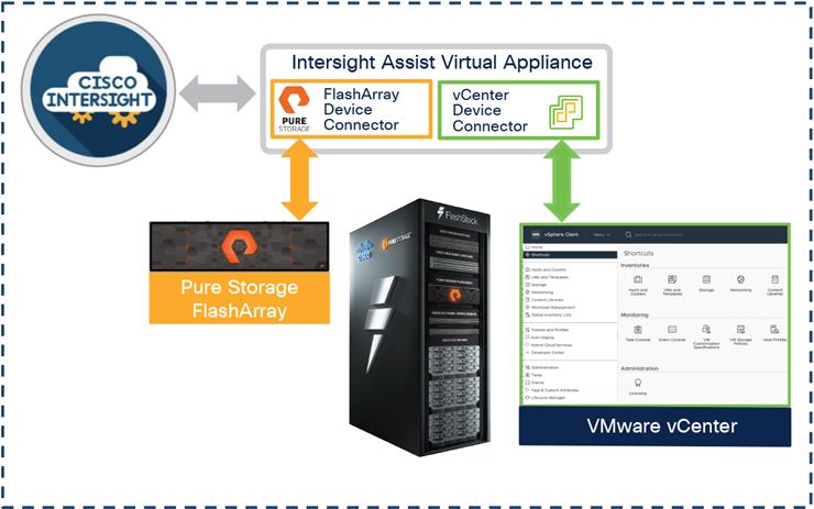
Cisco Intersight Assist device connector for VMware vCenter and Pure Storage FlashArray
The Cisco Intersight cloud integrates with VMware vCenter and Pure Storage FlashArray as follows (refer to Figure 14):
● The Cisco Intersight cloud uses the device connector running within the Cisco Intersight Assist virtual appliance to communicate with the VMware vCenter.
● The Cisco Intersight platform uses the device connector running within the Cisco Intersight Assist virtual appliance to integrate with Pure Storage FlashArray//X50 R3.
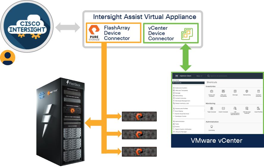
Cisco Intersight Cloud, VMware vCenter, and Pure Storage integration
The device connector provides a secure way for connected targets to send information and receive control instructions from the Cisco Intersight portal using a secure Internet connection. The integration brings the full value and simplicity of Cisco Intersight infrastructure management service to VMware hypervisor and FlashArray storage environments. The integration architecture enables FlashStack customers to use new management capabilities with no compromise in their existing VMware or FlashArray operations. IT users will be able to manage heterogeneous infrastructure from a centralized Cisco Intersight portal. At the same time, the IT staff can continue to use VMware vCenter and the Pure Storage dashboard for comprehensive analysis, diagnostics, and reporting of virtual and storage environments. The next section addresses the functions that this integration provides.
FlashStack with the Cisco UCS X-Series and Intersight solutions delivers a cloud-managed infrastructure solution on the latest Cisco UCS hardware. VMware vSphere 7.0 hypervisor is installed on the Cisco UCS X210c M6 compute nodes configured for stateless compute design using boot from SAN. Pure Storage FlashArray//X50 R3 provides the storage infrastructure required to set up the VMware environment. The Cisco Intersight cloud management platform configures and manages the infrastructure. The following sections discuss the solution requirements and design details.
Design requirements
The FlashStack with Cisco UCS X-Series and Intersight design meets the following general design requirements:
● Resilient design across all layers of the infrastructure with no single point of failure
● Scalable design with the flexibility to add compute capacity, storage, or network bandwidth as needed
● Modular design that you can replicate to expand and grow as the needs of your business grow
● Flexible design that can easily support different models of various components
● Simplified design with ability to automate and integrate with external automation tools
● Cloud-enabled design that you can configure, manage, and orchestrate from the cloud using a graphical user interface (GUI) or APIs
Physical topology
FlashStack with Cisco UCS X-Series supports both IP- and Fibre Channel-based storage access design. For the IP-based solution, Internet Small Computer System Interface (iSCSI) configuration on Cisco UCS and Pure Storage FlashArray sets up storage access including boot from SAN for the compute node. For the Fibre Channel designs, Cisco MDS 9132T switches connect Pure Storage FlashArray and Cisco UCS X-Series, and storage access uses the Fibre Channel network. The next section addresses the physical connectivity details for both IP and Fibre Channel designs.
IP-based storage access
Figure 15 shows the physical topology for the IP-based FlashStack.
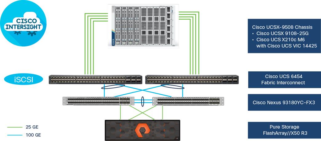
FlashStack – physical topology for IP connectivity
To validate the IP-based storage access in a FlashStack configuration, the components are set up as follows:
● Cisco UCS 6454 fabric interconnects provide the chassis and network connectivity.
● The Cisco UCSX-9508 modular chassis connects to fabric interconnects using Cisco UCSX 9108-25G IFM, where four 25 GE ports are used on each IFM to connect to the appropriate fabric interconnect. Depending on your workload requirements, you can use all eight ports for additional bandwidth to connect an IFM to a fabric interconnect.
● Cisco UCS X210c M6 servers contain fourth-generation Cisco VIC 14425 virtual interface cards.
● Cisco Nexus 93180YC-FX3 switches in Cisco NX-OS mode provide the switching fabric.
● Cisco UCS 6454 Fabric Interconnect 100-GE uplink ports connect to Cisco Nexus 93180YC-FX3 switches in a virtual port channel (vPC) configuration.
● The Pure Storage FlashArray//X50 R3 connects to the Cisco Nexus 93180YC-FX3 switches using four 25-GE ports.
● VMware 7.0 ESXi software is installed on Cisco UCS X210c M6 servers to validate the infrastructure.
Fibre Channel-based storage access
Figure 16 shows the physical topology of FlashStack for Fibre Channel connectivity.
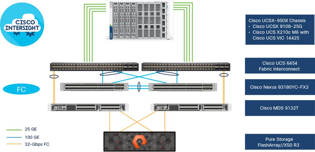
FlashStack – physical topology for Fibre Channel connectivity
To validate the Fibre Channel-based storage access in a FlashStack configuration, the components are set up as follows:
● Cisco UCS 6454 fabric interconnects provide the chassis and network connectivity.
● The Cisco UCSX-9508 modular chassis connects to fabric interconnects using Cisco UCSX 9108-25G IFM, where four 25-GE ports are used on each IFM to connect to the appropriate fabric interconnect.
● Cisco UCS X210c M6 servers contain fourth-generation Cisco VIC 14425 virtual interface cards.
● Cisco Nexus 93180YC-FX3 switches in Cisco NX-OS mode provide the switching fabric.
● Cisco UCS 6454 fabric interconnect 100-GE uplink ports connect to Cisco Nexus 93180YC-FX3 switches in a vPC configuration.
● Cisco UCS 6454 fabric interconnects are connected to the Cisco MDS 9132T switches using 32-Gbps Fibre Channel connections configured as a port channel for SAN connectivity.
● The Pure Storage FlashArray//X50 R3 connects to the Cisco MDS 9132T switches using 32-Gbps Fibre Channel connections for SAN connectivity.
● VMware 7.0 ESXi software is installed on Cisco UCS X210c M6 servers to validate the infrastructure.
VLAN configuration
Table 3 lists VLANs configured for setting up the FlashStack environment along with their usage.
Table 3. VLAN Usage
| VLAN ID |
Name |
Usage |
| 2 |
Native-VLAN |
Use VLAN 2 as a native instead of default VLAN id 1. |
| 3072 |
OOB-MGMT-VLAN |
An out-of-band management VLAN connects the management ports for various devices. |
| 19 |
IB-MGMT-VLAN |
VLAN used for all in-band management connectivity; for example, ESXi hosts, virtual-machine management, etc. |
| 172 |
VM-Traffic |
Virtual-machine data traffic VLAN |
| 3119* |
iSCSI-A |
iSCSI-A path for boot-from-SAN traffic |
| 3219* |
iSCSI-B |
iSCSI-B path for boot-from-SAN traffic |
| 3319 |
vMotion |
VMware vMotion traffic |
* iSCSI VLANs are not required when using Fibre Channel storage access.
Some of the highlights of VLAN usage follow:
● VLAN 3072 allows you to manage and access out-of-band management interfaces of various devices.
● VLAN 19 is used for in-band management of virtual machines, ESXi hosts, and other infrastructure services.
● A pair of iSCSI VLANs (3119 and 3219) are configured to provide access to block storage for ESXi hosts. You do not need these VLANs when configuring Fibre Channel connectivity.
Logical topology
In FlashStack deployments, each Cisco UCS server equipped with a Cisco VIC is configured for multiple virtual network interfaces (vNICs) that appear to the OS as standards-compliant PCIe endpoints. The end-to-end logical connectivity, including VLAN/VSAN usage between the server profile for an ESXi host and the storage configuration on Pure Storage FlashArray, is captured in the following sections.
Logical topology for IP-based storage access
Figure 17 captures the end-to-end connectivity design for IP-based storage access.
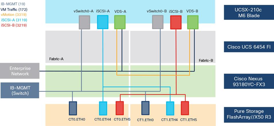
Logical connectivity for iSCSI design
Each ESXi host server profile supports:
● Managing the ESXi hosts using a common management segment
● Diskless SAN boot using iSCSI with persistent operating system installation for true stateless computing
● Six vNICs where:
◦ Two redundant vNICs (vSwitch0-A and vSwitch0-B) carry management traffic. The maximum transmission unit (MTU) value for these vNICs is set as a Jumbo MTU (9000).
◦ The vSphere distributed switch uses two redundant vNICs (VDS-A and VDS-B) to carry VMware vMotion traffic and customer application data traffic. The MTU for the vNICs is set to Jumbo MTU (9000).
◦ The iSCSI-A vSwitch uses one iSCSI-A vNIC to provide access to the iSCSI-A path. The MTU value for the vNIC is set to Jumbo MTU (9000).
◦ The iSCSI-B vSwitch uses one iSCSI-B vNIC to provide access to the iSCSI-B path. The MTU value for this vNIC is set to Jumbo MTU (9000).
● Each ESXi host (compute node) accesses virtual-machine datastores from Pure Storage FlashArray by using iSCSI to deploy virtual machines.
Logical topology for Fibre-Channel-based storage access
Figure 18 captures the end-to-end connectivity design for Fibre Channel-based storage access.
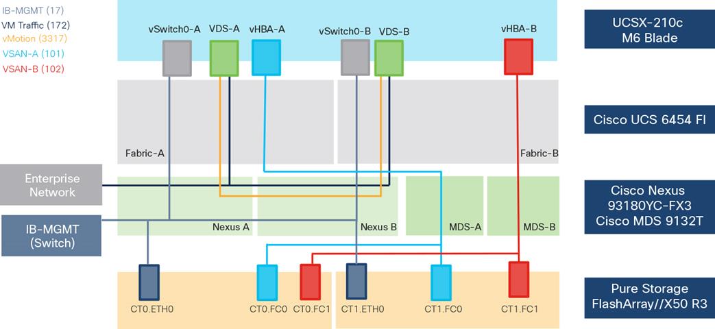
Logical connectivity for Fibre-Channel design
Each ESXi server profile supports:
● Managing the ESXi hosts using a common management segment
● Diskless SAN boot using Fibre Channel with persistent operating system installation for true stateless computing
● Four vNICs where:
◦ Two redundant vNICs (vSwitch0-A and vSwitch0-B) carry management traffic. The MTU value for these vNICs is set as a Jumbo MTU (9000).
◦ The vSphere Distributed switch uses two redundant vNICs (VDS-A and VDS-B) to carry VMware vMotion traffic and customer application data traffic. The MTU for the vNICs is set to Jumbo MTU (9000).
◦ One vHBA defined on Fabric A provides access to the SAN-A path.
◦ One vHBA defined on Fabric B provides access to the SAN-B path.
● Each ESXi host (compute node) accesses virtual-machine datastores from Pure Storage FlashArray by using Fibre Channel for deploying virtual machines.
Computing system connectivity
The Cisco UCSX-9508 chassis is equipped with two Cisco UCSX 9108-25G IFM. It connects to each Cisco UCS 6454 fiber interconnect using four 25-GE ports from each IFM, as shown in Figure 19.
Note: If you need more bandwidth, you can connect all 8 ports on the two IFM to each fiber interconnect.
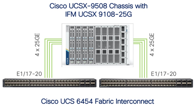
Cisco UCSX-9508 connectivity to Cisco UCS fabric interconnects
Cisco Nexus Ethernet connectivity
The Cisco Nexus 93180YC-FX3 device configuration covers the core networking requirements for Layer 2 and Layer 3 communication. Some of the important NX-OS features implemented within the design include:
● Feature interface-vlan: Allows configuration of VLAN IP interfaces within the switch as gateways.
● Feature HSRP: Allows for Hot Standby Routing Protocol configuration for high availability.
● Feature LACP: Allows for use of Link Aggregation Control Protocol (LACP 802.3ad) by the port channels configured on the switch.
● Feature vPC: Enables Virtual Port-Channel (vPC) to present the two Nexus switches as a single “logical” port channel to the connecting upstream or downstream device.
● Feature LLDP: Link Layer Discovery Protocol, a vendor-neutral device discovery protocol that allows the discovery of both Cisco and third-party devices.
● Feature NX-API: Improves the accessibility of the command-line interface (CLI) by making them available outside of the switch by using HTTP/Secure HTTPS (HTTP/HTTPS); this feature helps with configuring the Nexus switch remotely using the automation framework.
● Feature UDLD: Enables Unidirectional Link Detection for various interfaces
Cisco UCS 6454 Fabric Interconnect Ethernet connectivity
Cisco UCS 6454 fabric interconnects are connected to Cisco Nexus 93180YC-FX3 switches using 100-GE connections configured as VPCs. Each fabric interconnect is connected to both Nexus switches using a 100-GE connection, but you can easily add additional links to the port channel to increase the bandwidth as needed. Figure 20 illustrates the physical connectivity details.
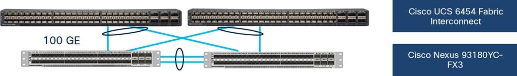
Figure 20 Cisco UCS 6454 fabric interconnect Ethernet connectivity
Pure Storage FlashArray//X50 R3 Ethernet connectivity
Pure Storage FlashArray controllers are connected to Cisco Nexus 93180YC-FX3 switches using redundant 25-GE connections. Figure 21 illustrates the physical connectivity details.
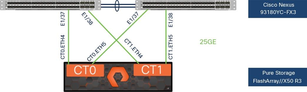
Pure Storage FlashArray//X50 R3 IP connectivity
Cisco MDS SAN Connectivity – Fibre Channel design
The Cisco MDS 9132T is the critical design component that brings together the 32-Gbps Fibre Channel capabilities to the FlashStack design. A redundant 32-Gbps Fibre Channel SAN configuration is deployed using two Cisco MDS 9132Ts switches. Some of the important MDS features implemented within the design follow:
● Feature NPIV: N port identifier virtualization (NPIV) provides a means to assign multiple Fibre Channel IDs to a single N port.
● Feature fport-channel-trunk: F-port-channel-trunks allow for the fabric logins from the NPV switch to be virtualized over the port channel. This feature provides nondisruptive redundancy if individual member links fail.
● Smart-Zoning: This feature reduces the number of Ternary Content Addressable Memory (TCAM) entries by identifying the initiators and targets in the environment.
Cisco UCS 6454 Fabric Interconnect SAN connectivity
For SAN connectivity, each Cisco UCS 6454 fabric interconnect is connected to a Cisco MDS 9132T SAN switch using two 32-Gbps Fibre Channel port-channel connections, as shown in Figure 22:
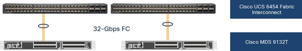
Cisco UCS 6454 fabric interconnect SAN connectivity
Pure Storage FlashArray//X50 R3 SAN connectivity
For SAN connectivity, each Pure Storage FlashArray controller is connected to both of the Cisco MDS 9132T SAN switches using 32-Gbps Fibre Channel connections, as shown in Figure 23.
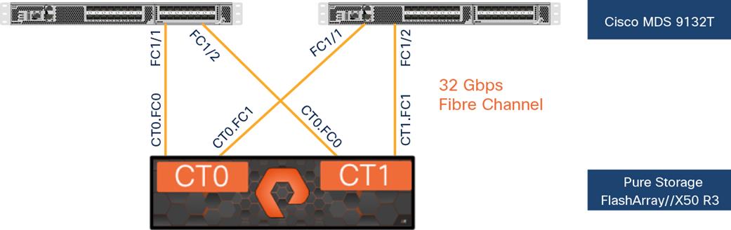
Pure FlashArray SAN connectivity
Cisco UCS X-Series configuration – Cisco Intersight managed mode
Cisco Intersight managed mode standardizes policy and operation management for the Cisco UCS X-Series. The compute nodes in the Cisco UCS X-Series are configured using server profiles defined in the Cisco Intersight cloud. These server profiles derive all the server characteristics from various policies and templates. At a high level, configuring the Cisco UCS platform using Cisco Intersight managed mode consists of the steps shown in Figure 24.
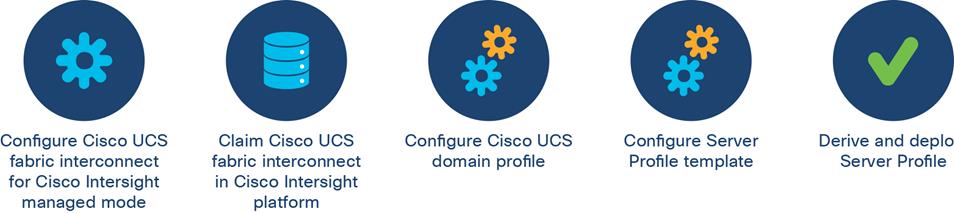
Configuration steps for Cisco Intersight managed mode
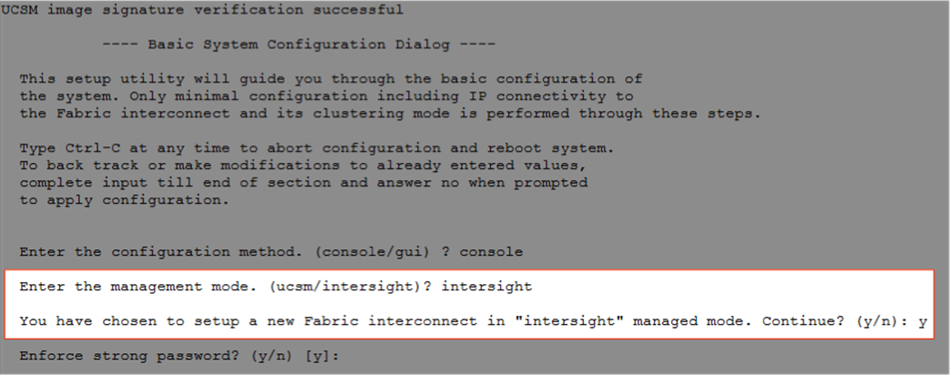
Setting up Cisco UCS fabric interconnect for Cisco Intersight managed mode
During the initial configuration, for manage mode the configuration wizard enables you to choose whether to manage the fabric interconnect through Cisco UCS Manager or the Cisco Intersight platform. You can switch the manage mode for the fabric interconnects between the Cisco Intersight cloud and Cisco UCS Manager at any time; however, Cisco UCS fabric interconnects must be set up in Cisco Intersight managed mode to configure the Cisco UCS X-Series system. The following screenshot shows the dialog during initial configuration of Cisco UCS fabric interconnects for setting up Cisco Intersight managed mode:
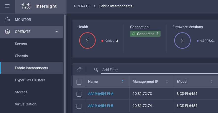
Claiming a Cisco UCS fabric interconnect in Cisco Intersight platform
After setting up the Cisco UCS fabric interconnect for Cisco Intersight managed mode, you can claim fabric interconnects to a new or existing Cisco Intersight account. When you successfully add a Cisco UCS fabric interconnect to the Cisco Intersight platform, all future configuration steps are completed in the Cisco Intersight portal. The following screenshot shows the Cisco Intersight cloud adding fabric interconnects as targets.
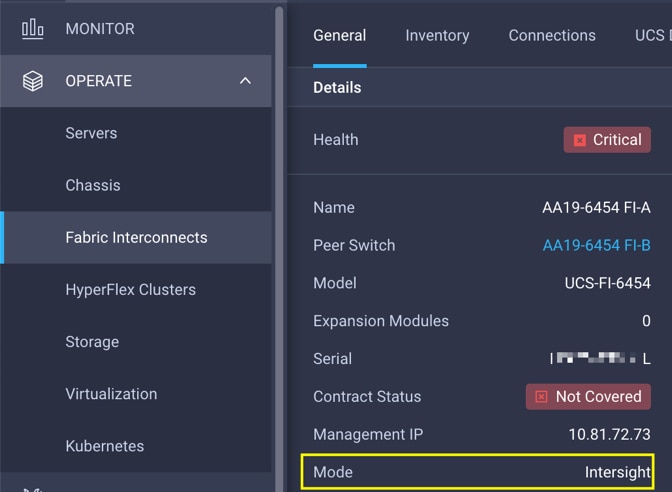
You can verify whether a Cisco UCS fabric interconnect is in Cisco UCS Manager managed mode or Cisco Intersight managed mode by clicking the fabric interconnect name and looking at the detailed information screen for the fabric interconnect, as shown in this screenshot:
Cisco UCS domain profile
A Cisco UCS domain profile configures a fabric interconnect pair through reusable policies, allows configuration of the ports and port channels, and configures the VLANs and VSANs to be used in the network. It defines the characteristics of and configures the ports on the fabric interconnects. You can assign one Cisco UCS domain profile to one fabric interconnect domain; the Cisco Intersight platform supports the attachment of one port policy per Cisco UCS domain profile.
Some of the characteristics of the Cisco UCS domain profile in the FlashStack environment include:
● A single domain profile is created for the pair of Cisco UCS fabric interconnects.
● Unique port policies are defined for the two fabric interconnects.
● The VLAN configuration policy is common to the fabric interconnect pair because both fabric interconnects are configured for the same set of VLANs.
● The VSAN configuration policies (Fibre Channel connectivity option) are unique for the two fabric interconnects because the VSANs are unique.
● The Network Time Protocol (NTP), network connectivity, and system Quality-of-Service (QoS) policies are common to the fabric interconnect pair.
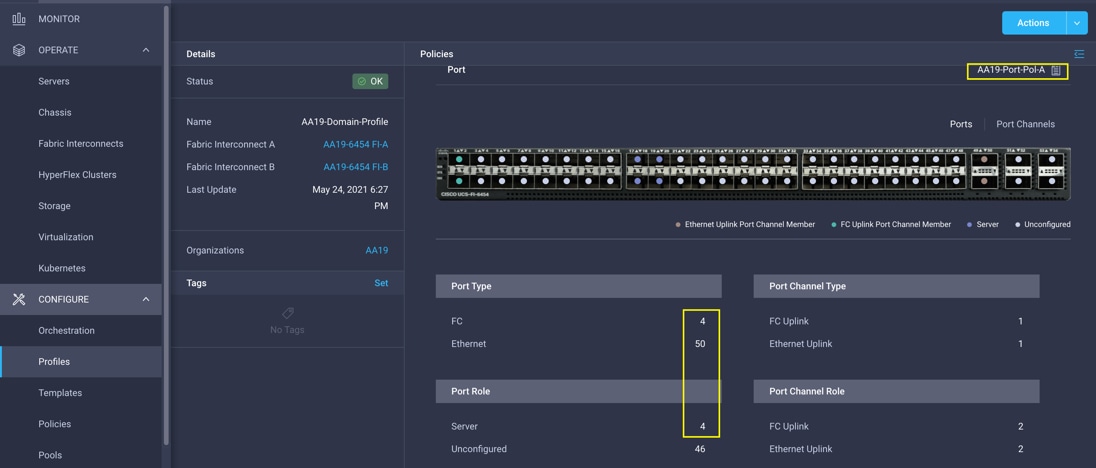
After the Cisco UCS domain profile has been successfully created and deployed, the policies, including the port policies, are pushed to Cisco UCS fabric interconnects. You can easily clone the Cisco UCS domain profile to install additional Cisco UCS systems. When cloning the Cisco UCS domain profile, the new Cisco UCS domains use the existing policies for consistent deployment of additional Cisco UCS systems at scale. This screenshot shows the Cisco UCS domain profile:
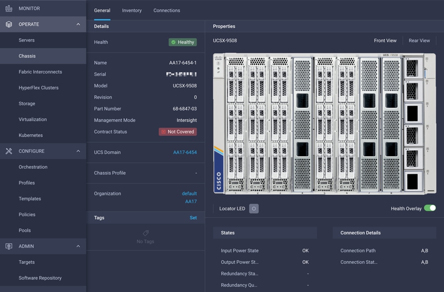
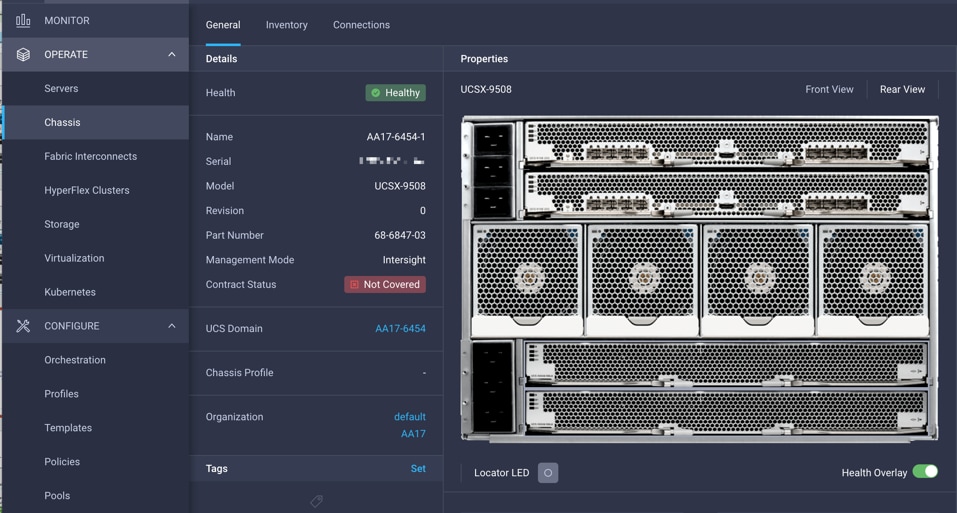
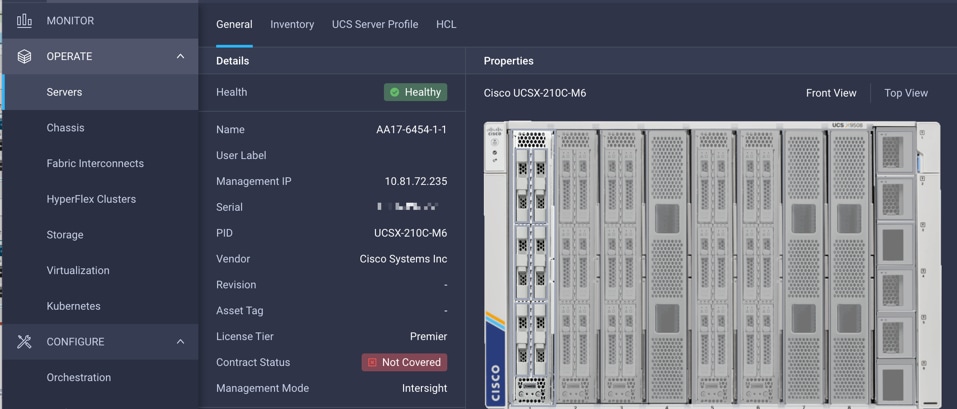
The Cisco UCSX-9508 chassis and Cisco UCS X210c M6 compute nodes are automatically discovered after successful configuration of the ports using the domain profile. The following screenshots show the front and rear views of the Cisco UCSX-9508 chassis, respectively, followed by the Cisco UCS X210c M6 compute nodes:
Server profile template
A server profile template enables resource management by simplifying policy alignment and server configuration. You can create a server profile template by using the server profile template wizard, which groups the server policies into the following four categories to provide a quick summary view of the policies that are attached to a profile:
● Compute policies: Basic input/output system (BIOS), boot order, and virtual media policies
● Network policies: Adapter configuration and LAN and SAN connectivity policies
◦ The LAN connectivity policy requires you to create an Ethernet network policy, an Ethernet adapter policy, and an Ethernet QoS policy.
◦ The SAN connectivity policy requires you to create a Fibre Channel network policy, a Fibre Channel adapter policy, and a Fibre Channel QoS policy. A SAN connectivity policy is required only for the Fiber Channel connectivity option.
● Storage policies: Not used in FlashStack
● Management policies: Device connector; Intelligent Platform Management Interface (IPMI) over LAN; Lightweight Directory Access Protocol (LDAP); local user; network connectivity; Simple Mail Transfer Protocol (SMTP); Simple Network Management Protocol (SNMP); Secure Shell (SSH) Protocol; Serial over LAN (SOL); syslog; and virtual keyboard, video, and mouse (KVM) policies
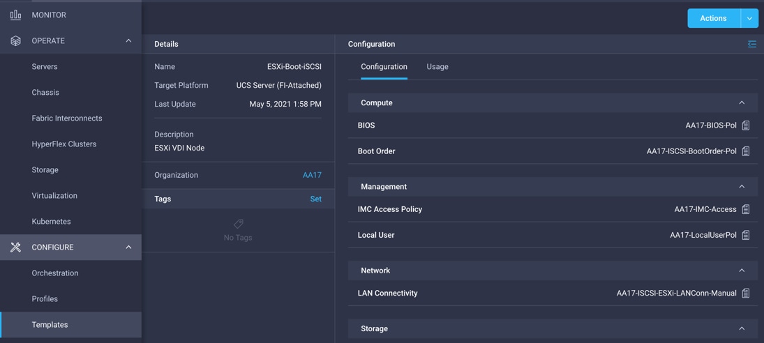
Some of the characteristics of the server profile template for FlashStack include:
● BIOS policy is created to specify various server parameters in accordance with FlashStack best practices.
● Boot order policy defines virtual media (KVM mapper DVD), all SAN paths for Pure Storage FlashArray (iSCSI or Fibre Channel interfaces), and Unified Extensible Firmware Interface (UEFI) shell.
● The IMC access policy defines the management IP address pool for KVM access.
● The local user policy is used to enable KVM-based user access.
● For iSCSI storage access, the LAN connectivity policy is used to create six virtual network interface cards (vNICs)—two for the management virtual switch (vSwitch0), two for the application VDS, and one each for iSCSI A/B vSwitches. Various policies and pools are also created for the vNIC configuration.
● For Fibre Channel storage access, the LAN connectivity policy is used to create four vNICs—two for management virtual switches (vSwitch0) and two for a VDS—along with various policies and pools.
● For Fibre Channel connectivity, the SAN connectivity policy creates two virtual host bus adapters (vHBAs)—one each for SANs A and B—along with various policies and pools. The SAN connectivity policy is not required for iSCSI setup.
The following screenshot shows various policies associated with the server profile template:
Derive and deploy server profiles from server profile template
Cisco Intersight server profile allows you to deploy server configurations directly on the compute nodes based on polices defined in the server profile template. After a server profile template is successfully created, you can derive server profiles from the template and associate them with the Cisco UCS X210c M6 compute nodes, as shown in the following screenshot:
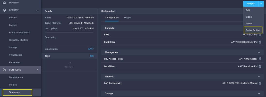
On successful deployment of the server profile, the Cisco UCS X210c M6 server is configured with parameters defined in the server profile, including the ability to boot from a storage LUN hosted on Pure Storage FlashArray.
Pure Storage FlashArray – storage design
To set up Pure Storage FlashArray you must configure the following items:
● Volumes
◦ ESXi boot LUNs: These LUNs enable ESXi host boot from SAN functions using iSCSI or Fibre Channel.
◦ The vSphere environment: vSphere uses the infrastructure datastore(s) to store the virtual machines.
● Hosts
◦ All FlashArray ESXi hosts are defined.
◦ You should add every active initiator for a given ESXi host.
● Host groups
◦ All ESXi hosts in a VMware cluster are part of the host group.
◦ Host groups are used to mount Infrastructure and swap datastores in the VMware environment.
The volumes, interfaces, and VLAN/VSAN details are shown in Figures 25 and 26 for iSCSI and Fibre Channel connectivity, respectively.
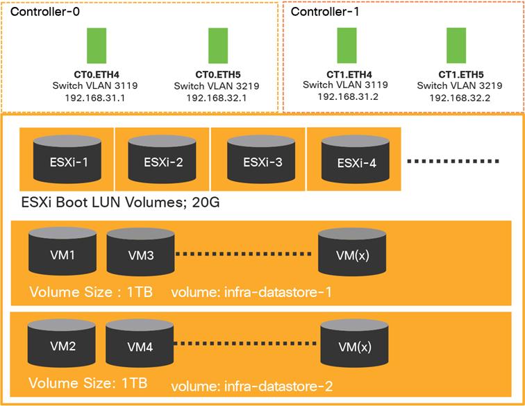
Pure Storage FlashArray volumes and interfaces – iSCSI configuration

Pure Storage FlashArray volumes and interfaces – Fibre Channel configuration
VMware vSphere – ESXi design
Multiple vNICs (and vHBAs) are created for the ESXi hosts using the Cisco Intersight server profile and are then assigned to specific virtual and distributed switches. The vNIC and (optional) vHBA distribution for the ESXi hosts follows:
● Two vNICs (one on each fabric) for vSwitch0 to support core services such as management traffic
● Two vNICs (one on each fabric) for vSphere VDS to support customer data traffic and vMotion traffic
● One vNIC each for Fabric-A and Fabric-B for iSCSI storage access and stateless SAN boot; these vNICs are required only if you want iSCSI connectivity
● One vHBA each for Fabric-A and Fabric-B for Fibre Channel storage access and stateless SAN boot; these vHBAs are required only if you want Fibre Channel connectivity
Figures 27 and 28 show the ESXi vNIC configuration in detail for iSCSI and Fibre Channel, respectively.
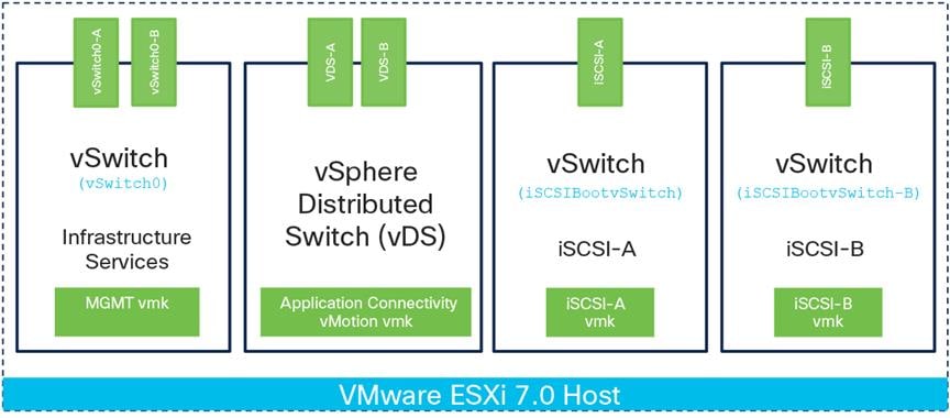
VMware vSphere – ESXi host networking for iSCSI connectivity
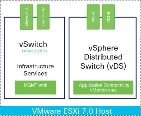
VMware vSphere – ESXi host networking for Fiber Channel connectivity
Cisco Intersight integration with VMware vCenter and Pure Storage FlashArray
The Cisco Intersight platform works with Pure Storage FlashArray and VMware vCenter using third-party device connectors. Because third-party infrastructure does not contain any built-in Intersight device connectors, a Cisco Intersight Assist virtual appliance enables the Cisco Intersight platform to communicate with third-party devices.
Note: A single Cisco Intersight Assist virtual appliance can support both Pure Storage FlashArray and VMware vCenter.
Cisco Intersight integration with VMware vCenter and Pure Storage FlashArray enables you to perform the following tasks right from the Cisco Intersight dashboard:
● Monitor the virtualization and storage environment
● Add various dashboard widgets to obtain useful at-a-glance information
● Perform common virtual-machine tasks such as power on/off, remote console, etc.
● Orchestrate both virtual and storage environments to perform common configuration tasks
The sections that follow address the details of these operations. Because the Cisco Intersight cloud is a SaaS platform, the monitoring and orchestration capabilities are constantly being added and delivered seamlessly from the cloud.
Figure 29 illustrates management of Pure Storage FlashArray and VMware vCenter with Cisco Intersight Assist.
Note: The monitoring capabilities and orchestration tasks and workflows discussed in the fol-lowing sections provide just an in-time snapshot for your reference. For the most up-to-date list of capabilities and features, you should use the help and search capabilities in the Cisco Intersight platform.
Managing Pure Storage FlashArray and VMware vCenter with Cisco Intersight Assist
Licensing requirement
A Cisco Intersight Advantage license is required to integrate and view various parameters for Pure Storage FlashArray and VMware vCenter in the Cisco Intersight cloud. A Cisco Intersight Premier license is required to use Cisco Intersight orchestration and workflows to provision the storage and virtual environments..
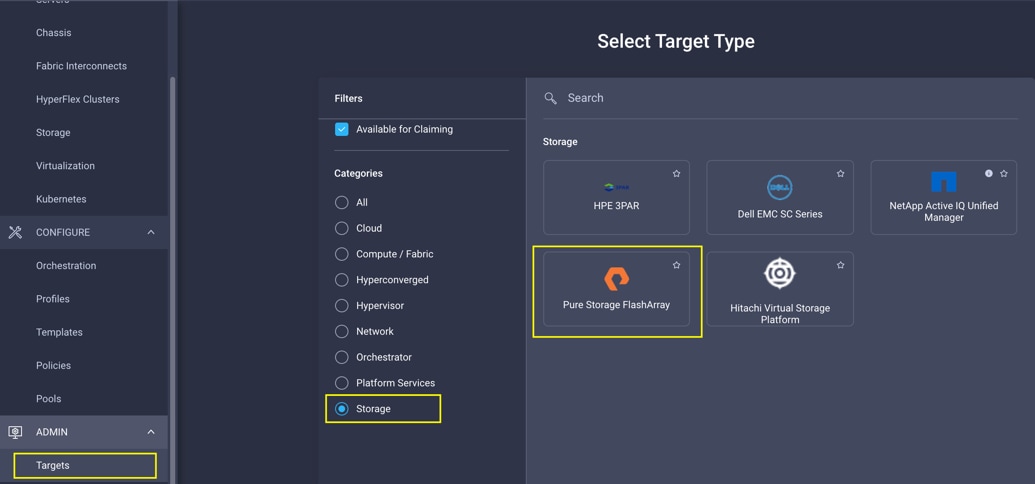
Integrating Cisco Intersight platform with Pure Storage FlashArray
To integrate Pure Storage FlashArray with the Cisco Intersight platform, you must deploy a Cisco Intersight Assist virtual appliance and claim Pure Storage FlashArray as a target in the Cisco Intersight application, as shown in the following screenshot:
Obtaining storage-level information
After successfully claiming the Pure Storage FlashArray as a target, you can view storage-level information in the Cisco Intersight application:
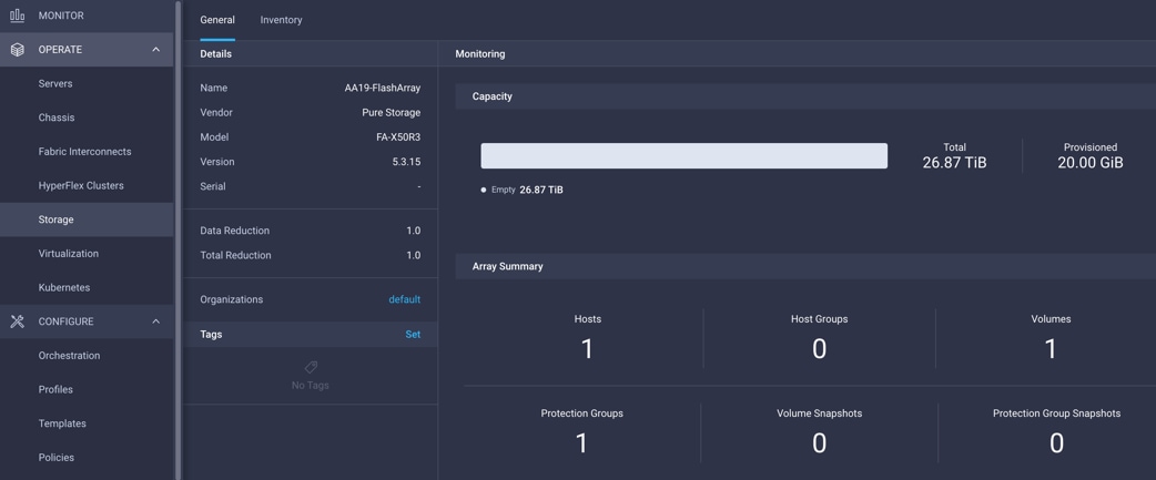
Table 4 lists some of the core Pure Storage FlashArray information presented through the Cisco Intersight cloud.
Table 4. Pure Storage FlashArray information in Cisco Intersight cloud
| Category |
Name |
Details |
| General |
Name |
Name of the controller |
| Vendor |
Pure Storage |
|
| Model |
Pure Storage FlashArray model information (for example, FA-X50R3) |
|
| Version |
Software version |
|
| Serial |
Serial number |
|
| Data reduction |
Storage efficiency |
|
| Total reduction |
Storage efficiency |
|
| Monitoring |
Capacity |
Total, used, and provisioned system capacity |
| Array |
Summary of hosts, host groups, volumes, etc. in the system |
|
| Inventory |
Hosts |
Hosts defined in the system and associated ports, volumes, and protection of group information |
| Host groups |
Host groups defined in the system and associated hosts, volumes, and protection of groups in the system |
|
| Volumes |
Configured volumes and volume-specific information such as capacity, data reduction, etc. |
|
| Protection group |
Protection groups defined in the system and associated targets, members, etc. |
|
| Controllers |
FlashArray controllers and their state, version, and model information |
|
| Drives |
Storage drive–related information, including type and capacity information |
|
| Ports |
Information related to physical ports, including World Wide Port Name (WWPN) and iSCSI Qualified Name (IQN) information |
Storage widget in the dashboard
You can also add the storage dashboard widgets to the Cisco Intersight platform for viewing Pure Storage FlashArray information at-a-glance on the Cisco Intersight dashboard:
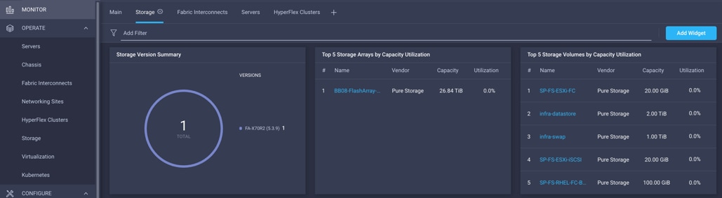
These storage widgets provide useful information such as:
● Top-five storage arrays and capacity usage
● Top-five storage volumes by capacity usage
● Storage versions summary, providing information about the software version and the number of storage systems running that version
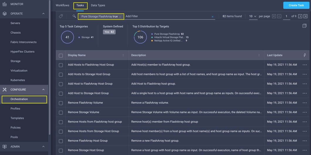
Cisco Intersight Orchestrator – Pure Storage FlashArray
The Cisco Intersight Cloud Orchestrator provides various workflows that you can use to automate storage provisioning. Some of the sample storage workflows available for Pure Storage FlashArray are listed in Table 5.
Table 5. Pure Storage FlashArray workflows in Cisco Intersight Orchestrator
| Name |
Details |
| New storage host |
Create a new storage host; if a host group is provided as input, then the host is added to the host group. |
| New storage host group |
Create a new storage host group; if hosts are provided as inputs, the workflow will add the hosts to the host group. |
| New VMFS Datastore |
Create a storage volume and build a VMFS datastore on the volume. |
| Remove storage host |
Remove a storage host. If a host group name is provided as input, the workflow will also remove the host from the host group. |
| Remove storage host group |
Remove a storage host group. If hosts are provided as input, the workflow will remove the hosts from the host group. |
| Remove VMFS datastore |
Remove a VMFS datastore and remove the backing volume from the storage device. |
| Update storage host |
Update the storage host details. If the inputs for a task are provided, then the task is run; otherwise, it is skipped. |
| Update VMFS datastore |
Expand a datastore on the hypervisor manager by extending the backing storage volume to specified capacity, and then expanding the data store to use the additional capacity. |
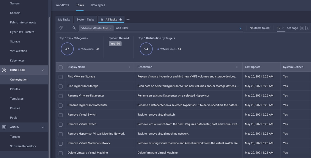
In addition to these workflows, Cisco Intersight Orchestrator also provides a large number of tasks for you to create a custom workflow based on your specific needs. A small subset of these tasks are highlighted in this screenshot:
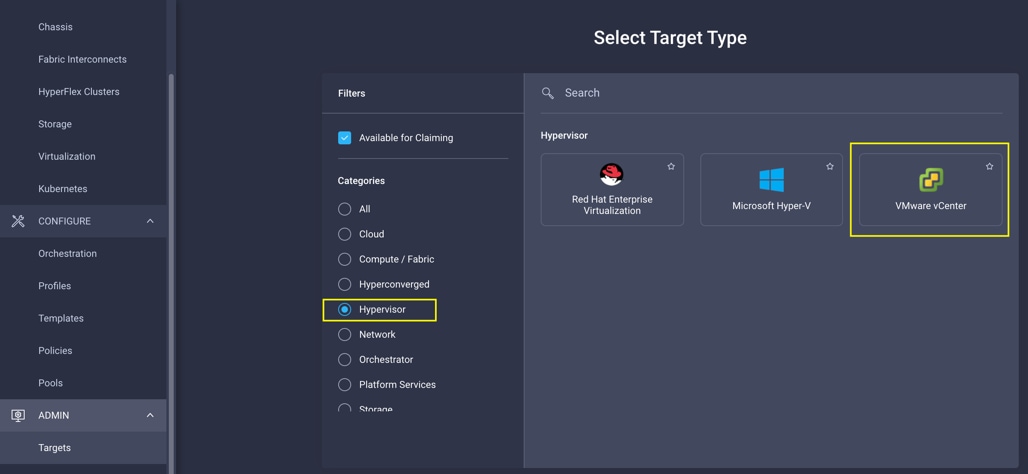
Integrating Cisco Intersight platform with VMware vCenter
To integrate VMware vCenter with Cisco Intersight Cloud, you can use VMware vCenter as a target with the Cisco Intersight Assist virtual appliance:
Obtaining hypervisor-level information
After successfully claiming the VMware vCenter as a target, you can view hypervisor-level information in the Cisco Intersight platform, including hosts, virtual machines, clusters, datastores, etc.:
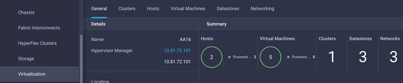
Table 6 lists some of the main virtualization properties presented in the Cisco Intersight cloud.
Table 6. Virtualization (VMware vCenter) information in Cisco Intersight cloud
| Category |
Name |
Details |
|
| General |
Name |
Name of the datacenter |
|
| Hypervisor manager |
Hostname or IP address of the vCenter |
||
| Clusters |
Name |
Name of the cluster |
|
| Datacenter |
Name of the datacenter |
||
| Hypervisor type |
ESXi |
||
| Hypervisor manager |
vCenter IP address or the hostname |
||
| CPU capacity |
CPU capacity in the cluster (GHz) |
||
| CPU consumes |
CPU cycles consumed by workloads (percentage and GHz) |
||
| Memory capacity |
Total memory in the cluster (GB) |
||
| Memory consumed |
Memory consumed by the workloads (percentage and GB) |
||
| Total number of cores |
All the CPU cores across various CPUs in the cluster |
||
| VMware cluster information allows you to access additional details about hosts and virtual machines associated with the cluster. |
|||
| Hosts |
Name |
Hostname or IP address |
|
| Server |
Server profile associated with the ESXi host |
||
| Cluster |
Cluster information if the host is part of a cluster |
||
| Datacenter |
VMware datacenter |
||
| Hypervisor type |
ESXi |
||
| Hypervisor manager |
vCenter IP address of hostname |
||
| Host information allows you to access additional details about clusters, virtual machines, datastores, and networking related to the current ESXi host. |
|||
| Virtual machines |
Name |
Name of the virtual machine |
|
| Guest OS |
Operating system; for example, RHEL, CentOS, etc. |
||
| Hypervisor type |
ESXi |
||
| Host |
ESXi host information for the virtual machine |
||
| Cluster |
VMware cluster name |
||
| Datacenter |
VMware datacenter name |
||
| IP address |
IP address(s) assigned to the virtual machine |
||
| Hypervisor manager |
IP address of hostname of the vCenter |
||
| Virtual-machine information allows you to access additional details about clusters, hosts, datastores, networking, and virtual disks related to the current virtual machine |
|||
| Datastores |
Name |
Name of the datastore in VMware vCenter |
|
| Type |
Network File System (NFS) or Virtual Machine File System (VMFS), etc. |
||
| Accessible |
Yes, if datastore is accessible; or no, if datastore is inaccessible |
||
| Thin provisioning |
Yes, whether or not thin provisioning is allowed; or no, if thin provisioning is not allowed |
||
| Multiple host access |
Yes, if multiple hosts can mount the datastore; or no, if the datastore allows only a single host |
||
| Storage capacity |
Space in GB or TB |
||
| Storage consumes |
Percentage and GB |
||
| Datacenter |
Name of VMware vCenter datacenter |
||
| Hypervisor manager |
vCenter hostname or IP address |
||
| Datastore information allows you to access additional details about hosts and virtual machines associated with the datastore. |
|||
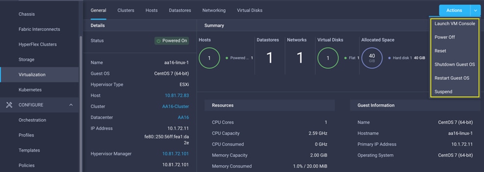
Interacting with the virtual machines
VMware vCenter integration with the Cisco Intersight platform allows you to interact directly with the virtual machines from the Cisco Intersight dashboard. In addition to providing in-depth information about a virtual machine, including the operating system, CPU, memory, hostname, and IP addresses assigned to the virtual machines, you can use the Cisco Intersight platform to perform the following actions on the virtual machines.
● Launch virtual-machine console
● Power off
● Reset
● Shut down guest OS
● Restart guest OS
● Suspend
Here is a screenshot showing the virtual-machine actions possible on the Cisco Intersight cloud:
Cisco Intersight Orchestrator – VMware vCenter
The Cisco Intersight Orchestrator provides various workflows that you can use to provision the virtual machines and hypervisor. Table 7 lists some of the sample workflows available for VMware vCenter.
Table 7. VMware vCenter workflows in Cisco Intersight Orchestrator
| Name |
Details |
| New VMFS datastore |
Create a storage volume and build a VMFS datastore on the volume. |
| New virtual machine |
Create a new virtual machine on the hypervisor from an OVA or OVF file. Datastore, Host/Cluster, and Image Uniform Resource Locator (URL) fields are mandatory. All other inputs are optional. |
| Remove VMFS datastore |
Remove the VMFS datastore and remove the backing volume from the storage device. |
| Update VMFS datastore |
Expand a datastore on the hypervisor manager by extending the backing storage volume to specified capacity, and then grow the datastore to use the additional capacity. |
In addition to these workflows, Cisco Intersight Orchestrator provides a large number of tasks for you to create custom workflows depending on your specific requirements. A small subset of these tasks are highlighted in this screenshot:
Deployment hardware and software
This section outlines the solution hardware and software components.
Hardware and software revisions
Table 8 lists the hardware and software releases for the FlashStack with the Cisco UCS X-Series and Cisco Intersight solution.
Table 8 Hardware and software components*
| Component |
|
| Network |
Cisco Nexus 93180YC-FX3 configured in NxOS mode |
| Cisco MDS 9132T |
|
| Compute |
Cisco UCS 6454 fabric interconnect in Cisco Intersight managed mode |
|
|
Cisco UCSX-9508 chassis and Cisco UCS X210c M6 compute nodes |
|
|
VMware ESXi 7.0 |
|
|
VMware vCenter Appliance 7.0 |
| Storage |
Pure Storage FlashArray//X50 R3; Purity//FA 6.1 |
* Target software releases are provided as a reference. Exact software versions will be part of upcoming Cisco Validated Designs.
A FlashStack solution is a validated approach for deploying Cisco and Pure Storage technologies and products for building shared private and public cloud infrastructure. With the introduction of the Cisco X-Series modular platform to the FlashStack, you now can manage and orchestrate the next-generation Cisco UCS platform from the cloud using the Cisco Intersight platform. Some of the important advantages of integrating Cisco UCS X-Series and Cisco Intersight cloud into the FlashStack solution include:
● Simpler and programmable infrastructure
● Power and cooling innovations and better airflow
● Fabric innovations for heterogeneous compute and memory composability
● Innovative cloud operations: Continuous feature delivery
● Design built for investment protection
In addition to the Cisco UCS X-Series hardware and software innovations, integration of the Cisco Intersight cloud platform with VMware vCenter and Pure Storage FlashArray delivers monitoring, orchestration, and workload optimization capabilities for different layers (virtualization and storage) of the FlashStack solution. The modular nature of the Cisco Intersight platform also provides an easy upgrade path to additional services such as workload optimization and Kubernetes.
This appendix includes links to various product pages.
Compute
● Cisco Intersight platform: https://www.intersight.com
● Cisco Intersight managed mode: https://www.cisco.com/c/en/us/td/docs/unified_computing/Intersight/b_Intersight_Managed_Mode_Configuration_Guide.html
● Cisco Unified Computing System: http://www.cisco.com/en/US/products/ps10265/index.html
● Cisco UCS 6400 Series fabric interconnects: https://www.cisco.com/c/en/us/products/collateral/servers-unified-computing/datasheet-c78-741116.html
Network
● Cisco Nexus 9000 Series switches:
http://www.cisco.com/c/en/us/products/switches/nexus-9000-series-switches/index.html
● Cisco MDS 9132T switches:
https://www.cisco.com/c/en/us/products/collateral/storage-networking/mds-9100-series-multilayer-fabric-switches/datasheet-c78-739613.html
Storage
● Pure Storage FlashArray//X:
https://www.purestorage.com/products/flasharray-x.html
Virtualization
● VMware vCenter server:
http://www.vmware.com/products/vcenter-server/overview.html
● VMware vSphere:
https://www.vmware.com/products/vsphere