MCTP-Based Server Configuration and Management in Cisco UCS M6 Generation White Paper
Available Languages
Bias-Free Language
The documentation set for this product strives to use bias-free language. For the purposes of this documentation set, bias-free is defined as language that does not imply discrimination based on age, disability, gender, racial identity, ethnic identity, sexual orientation, socioeconomic status, and intersectionality. Exceptions may be present in the documentation due to language that is hardcoded in the user interfaces of the product software, language used based on RFP documentation, or language that is used by a referenced third-party product. Learn more about how Cisco is using Inclusive Language.
Defined by Distributed Management Task Force (DMTF),1 the Management Component Transport Protocol (MCTP)2 is a communication model intended to facilitate communication between:
● Management controllers and other management controllers
● Management controllers and management devices
MCTP is a media-independent protocol for intercommunication among intelligent devices within the platform management subsystem of a managed computer system. This protocol is independent of the underlying physical bus properties, as well as the “data-link” layer messaging used on the bus. The physical and data-link layer methods for MCTP communication across a given medium are defined by companion “transport binding” specifications, such as MCTP over PCIe Vendor Defined Messaging (PCIe VDM)3 and MCTP over SMBus/ I2C.4 This approach enables future transport bindings to be defined to support additional buses such as USB, RMII, and others, without affecting the base MCTP specification.
Defined through a set of DMTF specifications, MCTP has been designed to carry multiple types of manageability-related traffic across a common medium. The base MCTP specification defines message types for supporting the initialization and configuration of MCTP itself, and to support vendor-specific messages over MCTP. Other message types, such as a Secure Protocol and Data Model (SPDM)5 and a Platform Level Data Model (PLDM),6 are available to achieve specific sets of goals, such as device authentication, retrieval of certificates, firmware measurements (through SPDM) and inventory, firmware update, monitoring, and control (through PLDM).
With the C220M6 and C240M6 generation of Cisco Unified Computing System™ servers (Cisco UCS®), we are enabling MCTP PCIe VDM (vendor-defined messaging) based management for supported devices. This will open up an entire area of new features as well as configuration and management flexibility. This white paper will attempt to introduce this new technology and its possibilities for customers.
Comparison with legacy protocols
Evolution of hardware-management protocols
Over the past few decades, hardware management protocols used at the system board level have been constantly evolving. In legacy systems, most of the systems management processors communicated with the hardware sensors and devices they monitored using low-speed serial protocols such as I2C 7. In many cases, the I2C-based monitoring fell back to individual OEM specific implementation as well, without any standards followed. With increasing complexity of systems and more fine-grained management and monitoring requirements, these low-speed serial protocols have become a bottleneck. They started limiting the capabilities of modern system’s management functions. As devices become more capable and powerful, the bandwidth required to manage and monitor them has also started increasing. The volume of telemetry information that can be gleaned from a device and then sent through an analysis tool is becoming huge. Also, expectations from customers of zero downtime mean that critical updates and patches now have to happen through sideband channels without affecting the actual work load of the device. All of these are simply not possible with legacy protocols.
Benefits of MCTP-based management
Cisco UCS is introducing MCTP PCIe VDM with our C2220M6 and C240M6 generation of servers, for selected devices that support this protocol, such as storage cards (UCSC-SAS-M6T, UCSC-RAID-M6T etc.). MCTP PCIe VDM uses the PCIE bus for communication between the Cisco Integrated Management Controller (IMC) and managed peripherals; as such, it can benefit from the high bandwidth and throughput and low latency of the PCIe bus. For example, an I2C bus can support a maximum speed of 3.4 Mbps while PCIE will support 4000 Mbps, more than 1000 times faster. This high bandwidth enables a feature set that was simply not addressable in the past, such as validating security certificates and validating digital signature on devices for enhanced security, doing sideband hot updates and hot patches of the running firmware, getting high-fidelity telemetry and debug information when needed, and so on. Since this is an industry-wide standard, the same architecture scales across different vendors and partners.
The following example illustrates how MCTP can be used within a hypothetical platform management subsystem implementation. More complex topologies, with multiple levels of bridges and greater numbers of buses and devices can be readily supported by MCTP as required.
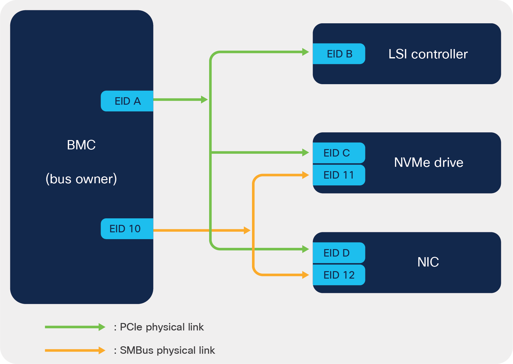
Example of MCTP topology
Figure 1 represents a simple MCTP subsystem consisting of one management controller (BMC) and three managed devices, namely an LSI controller, an NVMe drive, and an NIC. BMC being a management controller acts as the Bus Owner (BO) of this MCTP subsystem. The devices are interconnected through two types of physical communication links, PCIe and SMBus. Being the bus owner of this MCTP subsystem, BMC is responsible to discover the managed devices (or controllers) and assigns them a unique ID, also known as the Endpoint ID (EID). Each type of physical link forms an MCTP network, and each controller on a given network must have a unique EID. In this example, there are two types of MCTP network: first, the devices that communicate over PCIe links, and second, the devices that communicate over SMBus links.
In the Cisco UCS C220M6 and C240M6 server, BIOS configures the BMC, a.k.a. the CIMC (Cisco® Integrated Management Controller), as the MCTP “bus owner” of the PCIe subsystem. Once configured as the bus owner, the CIMC is responsible for discovering all MCTP-capable PCIe devices and managing them over the PCIe bus.
One of the restrictions of having a PCIe-based protocol is that the interface is only available when the host is completely powered on, due to the power requirements of the bus. In such cases, the system management software will typically fall back to lower-speed, but also low-power, buses such as I2C.
In the Cisco UCS C220M6 and C240M6 system, the MCTP over PCIe VDM support is enabled by default in the system software as well as in the Cisco IMC software. The firmware on the storage cards such as LSI 9500-8E already support MCTP out of the box. In some cases, if customers get unsupported cards, they are able to enable MCTP PCIe VDM support by using the Cisco Host Update Utility.
Security administrators in the industry are now not only concentrating on securing external network communications; they are also moving toward securing the onboard bus-level communication that occurs between devices present on the motherboard. The usage of a PCIe bus means that the system’s management controller has extremely high privileges in the system with respect to managing various devices.
In the Cisco UCS C220M6 and C240M6 system, any PCIe adapter or any host OS application connected with the CPU PCIe domain can initiate MCTP over PCIe VDM management commands and can alter the personality of the system. The PCIe adapter or host OS application can erase the data on the disks as well as cause loss of data. This can happen even without the involvement of the CIMC software in the system.
A typical block diagram of MCTP communication path in CISCO UCS C220M6 and C240M6 platforms is as shown below:
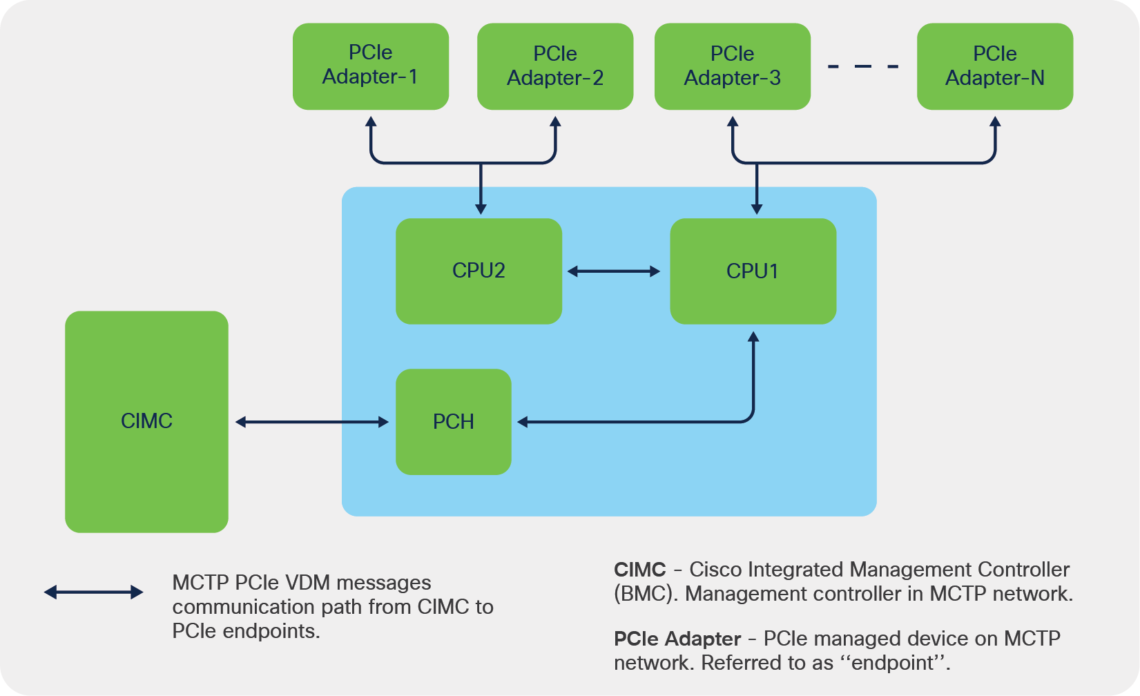
Cisco UCS MCTP communication block diagram
In the above block diagram, CIMC will be the “bus master” or “management controller”, and the PCIe adapters will be referred as “endpoints” in the MCTP network.
In view of securing onboard communication between the management controller (CIMC) and the managed devices, DMTF has specified the protocol standards given below:
DSP0274 Security Protocol and Data Model (SPDM) specification: https://www.dmtf.org/sites/default/files/standards/documents/DSP0274_1.0.1.pdf
DSP0275 Security Protocol and Data Model (SPDM) over MCTP Binding Specification: https://www.dmtf.org/sites/default/files/standards/documents/DSP0275_1.0.0.pdf
The DMTF security standards address the security functionalities described below:
● Establish the identity of the managed endpoints through a well-established certificate chain exchange method
● Verify the firmware running on the managed endpoints through firmware measurements at runtime, at constant intervals, to make sure the endpoints with which CIMC is communicating are genuine and running trusted firmware
● Secure the onboard communication channel between the management controller and management endpoints by encrypting the communication messages between the management controller and PCIe-managed devices (This design from DMTF is in progress and will be present in future DMTF specifications)
CISCO UCS platforms support the DSP0274 1.0.1 specification and the DSP0275 1.0.0 specification.
At host bootup, CIMC discovers the managed endpoints through the MCTP discovery procedure. The discovered MCTP endpoints will be authenticated through the SPDM authentication procedure as specified according to the DSP0274 1.0.1 specification.
The managed endpoint (referred as PCIe endpoint interchangeably in this document) is authenticated from the management controller through a certificate chain exchange and validating of the received certificate chain against the trusted root certificate present inside CIMC.
Certificate validation procedure in CIMC:
The SPDM certificate validation procedure works analogously to HTTPS digital certificate validation. Here the PCIe device responds with a digital certificate or chain of digital certificates that have a public key to verify the digital signature. CIMC, being the initiator of the validation procedure, is responsible for validating the complete digital certificate chain against the root certificates that CIMC carries, as well as for digital signature verification.
If CIMC is unable to validate either the digital certificate (or the chain of digital certificates) or the digital signature of a given PCIe device, then the managed PCIe endpoint is considered to be an unknown endpoint in the system. These unknown endpoints are flagged in the data center’s fault-monitoring system for further corrective action by the administrators.
The corrective action in these kinds of scenario can be as high as removing the flagged faulty PCIe endpoint and replacing with a new PCIe card.
CIMC SPDM user interfaces:
SPDM authentication status display:
CIMC provides user interfaces that display the SPDM authentication procedure status through all its user interfaces, including CLI, webUI, XMLAPI, and Redfish interfaces. The details of these can be obtained from Cisco UCS C220 M6 or Cisco UCS C240 M6 rack server user guides.
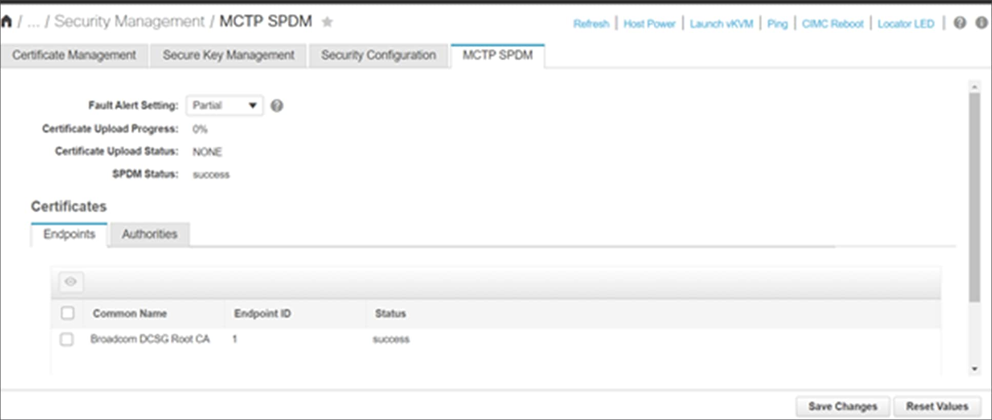
Cisco UCS SPDM status webUI screen
Figure 3 shows a typical webUI interface screen displaying the SPDM status for the endpoints discovered in the system.
The same data can be pulled from multiple servers using the XML/Redfish API scripts.
Example query1:
<configResolveClass cookie="3d94115fa0/c760abc0-7b7c-5ce9-5f34-78bcdff3e19b" inHierarchical="false" classId="mctpCertificateManagement"/>
Response:
<configResolveClass cookie="3d94115fa0/c760abc0-7b7c-5ce9-5f34-78bcdff3e19b" response="yes" classId="mctpCertificateManagement"> <outConfigs> <mctpCertificateManagement dn="sys/mctp-cert-mgmt" faultAlert="Partial" uploadStatus="NONE" uploadProgress="0%" overallSpdmStatus="success" ></mctpCertificateManagement></outConfigs> </configResolveClass>
Example query2:
<configResolveClass cookie="3d94115fa0/c760abc0-7b7c-5ce9-5f34-78bcdff3e19b" inHierarchical="false" classId="endPoint"/>
Response:
<configResolveClass cookie="3d94115fa0/c760abc0-7b7c-5ce9-5f34-78bcdff3e19b" response="yes" classId="endPoint"><outConfigs><endPoint slotId="1" spdmStatus="success" name="Broadcom DCSG Root CA" dn="sys/mctp-cert-mgmt/ep-1" ></endPoint></outConfigs></configResolveClass>
Example query3:
https://<cimc_ip>/redfish/v1/Systems/<server_serial_number>
Response:
"@odata.id": "/redfish/v1/Systems//<server_serial_number>",
...
...
"Oem": {
"Cisco" {
...
...
"MCTP": {
"FaultAlertSetting": "Partial",
"SPDMHandShakeStatus": "Completed"
}
}
},
These APIs make it possible for administrators to create script-based tools to collect SDPM security status across multiple servers in the data center.
When there is an SPDM authentication failure for an endpoint, a fault will be raised by the CIMC fault monitoring system, as below:
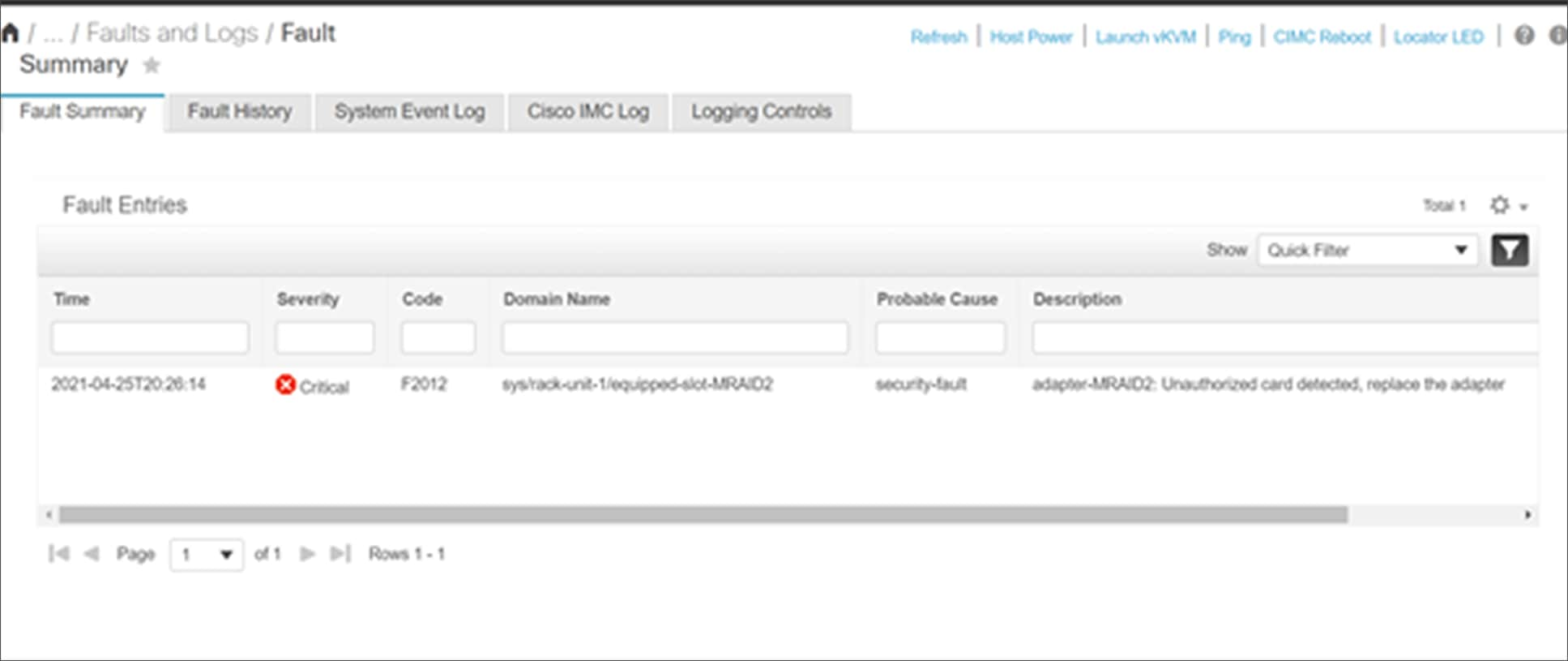
Cisco UCS SPDM fault display when endpoint authentication fails
Cisco UCS CIMC root certificate management for SPDM authentication:
Cisco UCS CIMC internally carries a list of trusted and validated root certificates. This root-certificate list will be used during security authentication procedures for each of the MCTP endpoints discovered, that supports an SPDM protocol 1.0.1 specification.
The SPDM security validation is pretty much a software functionality and can be enabled on the field for any PCIe endpoint through PCIe-card firmware updates. To support these scenarios, CIMC provides a root certificate management user interface functionality where users can manage root certificates to be present in the CIMC through upload and delete functionalities.
The root certificate management feature from CIMC provide users the capability to enable SPDM security support for various required PCIe endpoints on the server. This update can be done at run time and without any disruption to user infrastructure.
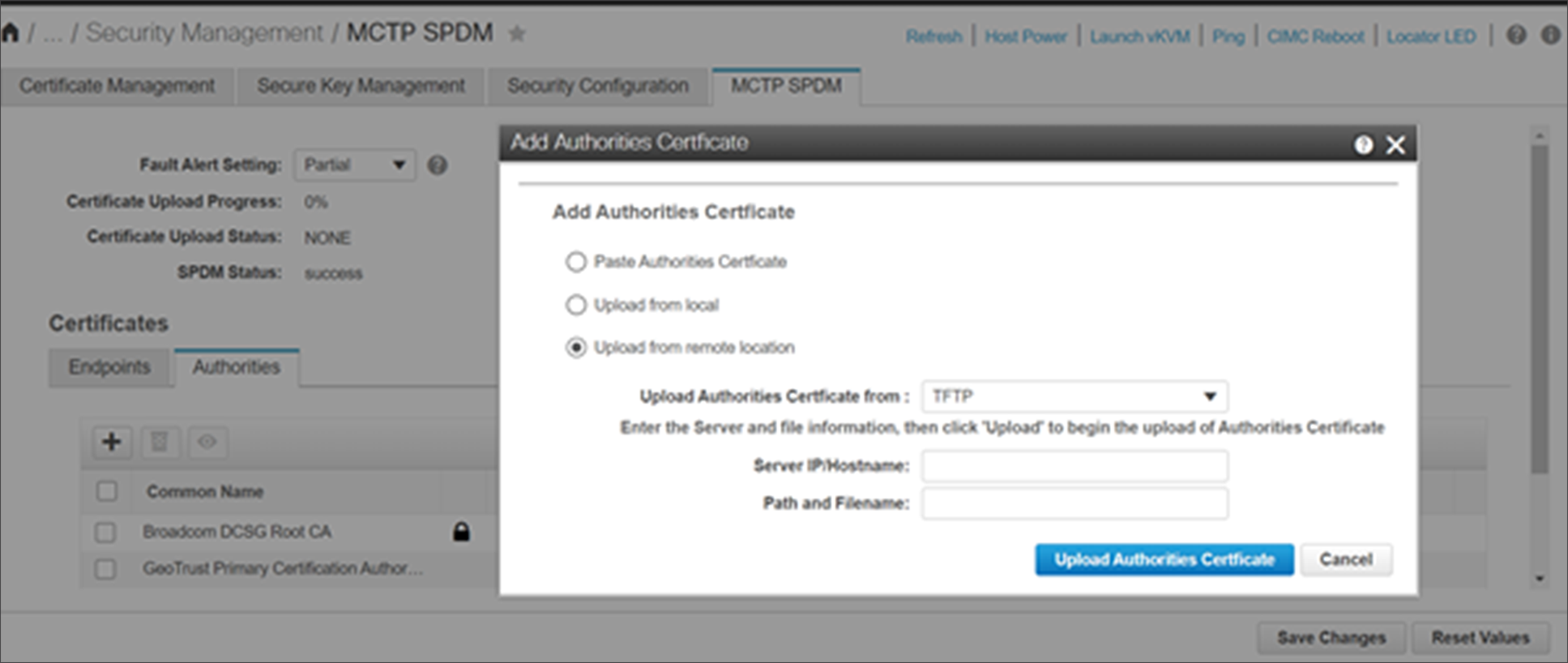
Cisco UCS SPDM root-certificate-upload webUI screen
Figure 5 shows a typical webUI interface screen displaying the option to upload a root certificate for SPDM authentication.
Root certificates are supported in both file_name.pem and file_name.der formats. The upload operation can be through remote upload or local browser-based upload or manual paste of certificate contents, as shown above.
The same operations can be performed for multiple servers using the XML/Redfish API scripts.
Example query4:
<configConfMo cookie="48df7e6fe4/7ce56c1f-cea6-0594-68d5-1781887dcca5" inHierarchical="false" dn="sys/mctp-cert-mgmt/upload-end-point-cert"> <inConfig> <uploadEndPointRootCACertificate dn="sys/mctp-cert-mgmt/upload-end-point-cert" adminAction="remote-cert-upload" protocol="scp" remoteServer=”<server_ip>" remoteFile="<cert_file_path>" user="xx" pwd="xx"/> </inConfig> </configConfMo>'
Response:
<configConfMo dn="sys/mctp-cert-mgmt/upload-end-point-cert" cookie="48df7e6fe4/7ce56c1f-cea6-0594-68d5-1781887dcca5" response="yes"><outConfig><uploadEndPointRootCACertificate dn="sys/mctp-cert-mgmt/upload-end-point-cert" adminAction="no-op" protocol="none" remoteServer="" remoteFile="" user="" pwd="" certificateContent="Certificate Content" uploadStatus="COMPLETED" uploadProgress="100%" status="modified" ></uploadEndPointRootCACertificate></outConfig></configConfMo>
Example query5:
https://<cimc_ip>/redfish/v1/Managers/CIMC/Oem/Cisco/SPDMTrustStore/Certificates -d '{
"CertificateType" : "PEM",
"CertificateString" : "<certificate string in PEM format>"
}'
Response:
{
"@odata.id": "/redfish/v1/Managers/CIMC/.. /Certificates/3",
"Id": "3",
"Name": "Certificate"
}
These APIs make it possible for administrators to create script-based tools to manage SPDM digital certificates across multiple servers in the data center.
After every root certificate upload, the SPDM authentication will be automatically triggered internally from CIMC for the PCIe endpoints that failed at SPDM authentication before the root-certificate-upload operation.
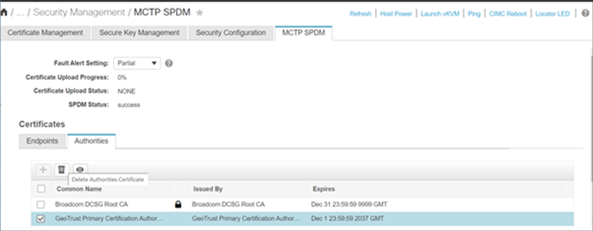
Cisco UCS SPDM root-certificate-delete operation webUI screen
After any root-certificate-delete operation, the discovered MCTP endpoints will undergo an SPDM authentication procedure again, and the faults will be raised accordingly for any authentication failing adapters.
MCTP over PCIe provides a huge advantage over bandwidth as compared to legacy SMBus methods of platform monitoring. The PCIe interface is more stable when compared to an SMBus interface, and platform monitoring and firmware updates are performed more efficiently with an MCTP over PCIe interface than using legacy SMBus interface methods. The MCTP over PCIe VDM method provides such advantages as alleviating the need for host downtime during updates of device firmware, providing complete logs from endpoints over sideband channels for debugging and analysis purposes, and many other functionalities where bandwidth requirements are very high.
Enabling MCTP over PCIe support on Cisco M6 UCS servers allows Cisco customers to progress further on adapting industry-wide server management standards such as NVMe-MI over MCTP for management of NVMe controllers, PLDM over MCTP for platform monitoring and control, device firmware updates, Field-Replaceable Unit (FRU) information, etc.
Cisco UCS C220M6 and C240M6 platforms incorporate SPDM functionality to enhance security to bus-level communication between the management controller and managed devices on the motherboard. This functionality will open up huge potential for data center users to set up secured server infrastructure without any security compromise.
2. https://www.dmtf.org/documents/pmci/management-component-transport-protocol-mctp-base-specification
3. https://www.dmtf.org/sites/default/files/standards/documents/DSP0238_1.1.0.pdf
4. https://www.dmtf.org/sites/default/files/standards/documents/DSP0237_1.1.0.pdf
5. https://www.dmtf.org/sites/default/files/standards/documents/DSP2058_1.0.0_1.pdf
6. https://www.dmtf.org/sites/default/files/standards/documents/DSP0240_1.0.0.pdf
7. https://www.csd.uoc.gr/~hy428/reading/i2c_spec.pdf
Authors
Kiran Bangalore Sathyanarayana (kibangal@cisco.com)
Vipin Nagar (vipnagar@cisco.com)
Sriranjan Bose (srbose@cisco.com)