Tuning Guidelines for Cisco UCS Virtual Interface Cards (White Paper)
Available Languages
Bias-Free Language
The documentation set for this product strives to use bias-free language. For the purposes of this documentation set, bias-free is defined as language that does not imply discrimination based on age, disability, gender, racial identity, ethnic identity, sexual orientation, socioeconomic status, and intersectionality. Exceptions may be present in the documentation due to language that is hardcoded in the user interfaces of the product software, language used based on RFP documentation, or language that is used by a referenced third-party product. Learn more about how Cisco is using Inclusive Language.
The goal of this document is to help administrators optimize network I/O performance both in standalone Cisco Unified Computing System™ (Cisco UCS®) servers and in configurations operating under Cisco UCS Manager. Note that although this document covers I/O performance optimization for the Cisco UCS virtual interface card (VIC), factors such as CPU, BIOS, memory, operating system, and kernel can contribute to overall I/O workload performance. For more specific performance optimization recommendations, please refer to Cisco® BIOS best practices tuning guides and Cisco Validated Designs for specific workloads.
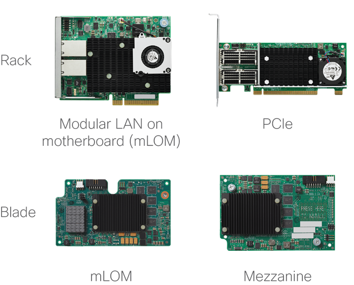
The Cisco UCS virtual interface card, or VIC, is a converged network adapter (CNA) designed for Cisco UCS blade and rack servers. The Cisco VIC is a stateless hardware device that is software programmable, providing management, data, and storage connectivity for Cisco UCS servers. Installed as a part of Cisco UCS or a standalone environment, the VIC is used to create PCI Express (PCIe) standards-compliant virtual interfaces: both virtual network interfaces (vNICs) and virtual host bus adapters (vHBAs). Indistinguishable from hardware NICs and HBAs, these interfaces can be dynamically defined and configured at the time of server provisioning.
Unless otherwise noted, this document is applicable to all past and present Cisco UCS VICs—for both blade and rack server platforms—operating under either Cisco UCS Manager or Cisco Integrated Management Controller (IMC).
The target audiences for this document are systems architects, system and server administrators, and any other technical staff who are responsible for managing Cisco UCS servers. Although this document is intended to appeal to the widest possible audience, the document assumes that the reader has an understanding of Cisco UCS hardware, terminology, and configuration.
The sections that follow describe the Cisco UCS VICs, vNICs, and the capabilities of various configurations.
The Cisco UCS VIC is available in a variety of models and form factors, allowing it to be supported in both Cisco UCS blade and rack servers (Figure 1). Depending on the generation and model, the adapter includes a PCIe 2.0 or 3.0 interface with either x8 or x16 connectivity and 10-, 20-, 25-, 40-, 50-, and 100-Gbps port speeds. For more specific information about capabilities, speed, operation, and server and network connectivity, refer to the data sheets for individual Cisco UCS VIC and server models.
Through unique Cisco® technology and policies, each Cisco UCS VIC provides up to 256 PCIe interfaces (the number depends on the Cisco UCS VIC model). Each virtual interface (vNIC or vHBA) created on the Cisco VIC application-specific integrated circuit (ASIC) is presented to the operating system as a fully standards-compliant PCIe bridge and endpoints. Each vNIC gets its own PCI address, memory space, interrupts, and so forth. The vNIC does not require any special driver and is supported as a part of the standard OS installation package.
Figure 2 provides a logical view of the Cisco UCS VIC, including its dual connections to a redundant pair of Cisco UCS fabric interconnects or LANs. The kernel’s standard Ethernet NIC (eNIC) driver allows the OS to recognize the vNICS. Having the most current eNIC driver can help improve network I/O performance, and Cisco recommends that the driver be updated based on the Cisco UCS Manager or Cisco IMC firmware and OS version level. The recommended driver level can be found through the Cisco UCS Hardware and Software Interoperability Matrix Tool (see the link at the end of this document).
|
|
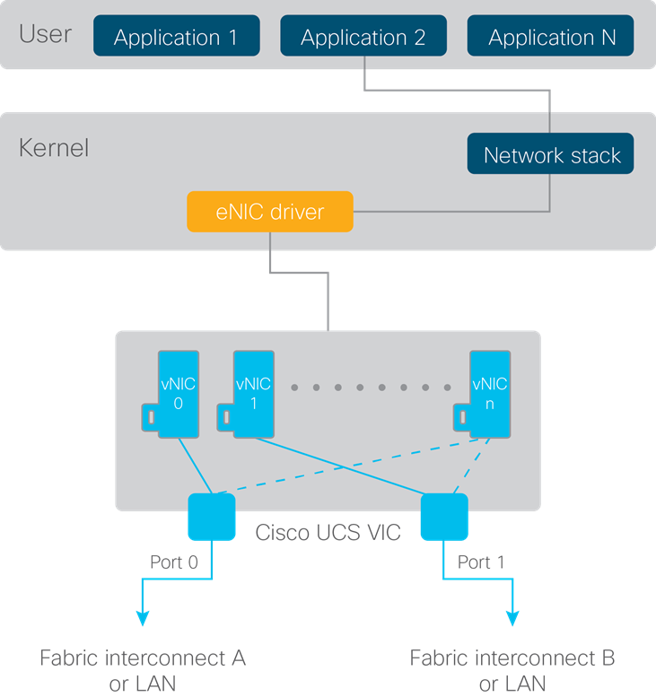
By default, two vNICs are created on each Cisco UCS VIC, with one bound to each of the adapter’s interfaces (ports 0 and 1). The server administrator can create additional vNICs to help segregate the different types of traffic that will be flowing through the adapter. For example, as shown in Figure 3, a server administrator might create four vNICs as follows:
● Two vNICs for management (one for side-A connectivity and one for side-B connectivity)
● Two additional vNICs for data (one for side-A connectivity and one for side-B connectivity)
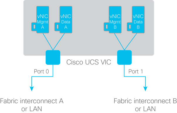
interconnects or LANs
The total number of supported vNICs is OS specific, and each OS allocates a different number of interrupts to the adapters. For the exact number of supported vNICs, refer to the Configuration Limit Guide on Cisco.com (see the link at the end of this document).
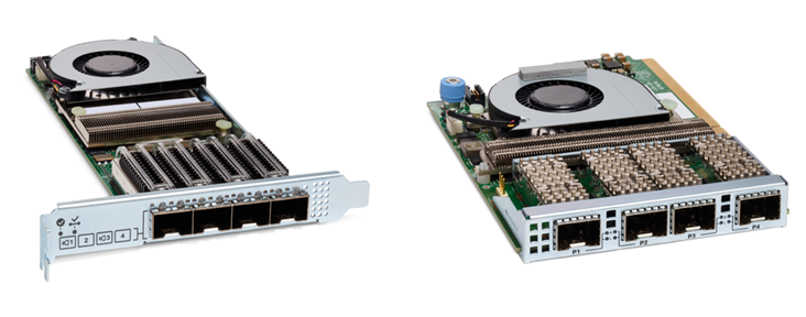
The 1200, 1300 and 1400 series Cisco UCS rack server VICs have two external ports, except for the 4th-generation Cisco UCS VICs 1455 1457, and 1467, which have four external adapter interfaces. On the Cisco UCS VIC 1455, 1457 and 1467, ports (1,2), and ports (3,4), are hardware port-channeled by default. This hardware port-channel is internal to the VIC 1455, 1457, and 1467 hardware. The hardware port-channel cannot be disabled in Cisco UCS Manager mode but when servers are in standalone mode the VIC hardware port-channel can be disabled from the Cisco IMC.
|
|
The port speed that is ultimately presented to the OS varies depending on the network connectivity.
● For Cisco UCS C-Series Rack Servers, the port speed is straightforward: it is simply the physical port speed of the PCIe adapter. Exception to this would be the 4-port Cisco UCS VICs 1455, 1457, and 1467 with the default VIC hardware port-channeled enabled, and in this case the port speed seen by the operating system is that of the port-channel (10-, 20-, 25- or 50-Gbps) depending on how many links of the port-channel are up and at what speed. In port-channel mode for VIC 1455, 1457, and 1467, each vNIC on the card is bound to one of the hardware port-channels.
● For Cisco UCS B-Series Blade Servers, the calculation is more complicated, because the number of connections from the adapter to the Cisco UCS fabric extender (also known as an I/O module, or IOM) varies depending on the model of both.
Table 1 compares the type of connectivity and the speed presented to the OS based on the Cisco UCS VIC blade adapters in combination with different Cisco UCS I/O module models and a Cisco UCS blade server. For example, when connected to higher-bandwidth Cisco UCS 2208, 2304, and 2408 Fabric Extender I/O modules, the adapter will have multiple 10-Gbps connections to the I/O module. For these cases, the multiple 10-Gbps connections are automatically combined into a hardware port channel (Figure 5)—a process that is transparent to the OS. The Cisco UCS VIC driver will then present the aggregate speed for the vNIC to the OS. The traffic distribution across the port channel is hashed in hardware across the physical links based on Layer 2, Layer 3, and Layer 4 information.
To help define available bandwidth, a flow is defined as a single TCP connection between two servers. As a result, although the OS may show that the vNIC can provide 20 or 40 Gbps of bandwidth (depending on the adapter combination), the maximum throughput for a single flow may be only 10, 25, or 40 Gbps because of the physical port connection. However, if there are multiple flows (for example, multiple TCP connections), then the aggregate throughput for the same vNIC can be 20 Gbps, assuming that the flows is hashed across the two 10-Gbps connections (or 40 Gbps across four 10-Gbps connections). In the case of the Cisco UCS 2304 fabric extender, the server can connect at a true 40 Gbps (depending on the adapter combination), allowing the flow to burst up to the entire 40-Gbps bandwidth of the connection. And with Cisco UCS 2408 fabric extender, the server can allow a single-flow burst of up to 25 Gbps (depending on the adapter combination).
|
|
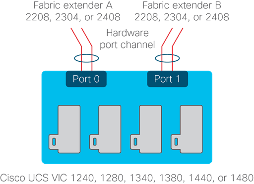
Table 1. vNIC bandwidth comparison based the combination of adapter and Cisco UCS fabric interconnect
| Cisco UCS Blade adapter |
Cisco UCS IOM |
Physical connection |
OS vNIC speed |
Maximum bandwidth for a single flow1 |
Maximum aggregate bandwidth for vNIC |
| VIC 1240/1340/1440 or 1280/1380/1480 |
2204
|
10 Gbps
|
10 Gbps
|
10 Gbps
|
10 Gbps
|
| VIC 1240/1340 Plus |
2204
|
2x10 Gbps in port-channel
|
20 Gbps
|
10 Gbps
|
20 Gbps
2
|
| VIC 1240/1340/1440 or 1280/1380/1480 |
2208
|
2x10 Gbps in port-channel
|
20 Gbps
|
10 Gbps
|
20 Gbps
2
|
| VIC 1240/1340 Plus |
2208
|
4x10 Gbps in port-channel
|
40 Gbps
|
10 Gbps
|
40 Gbps
2
|
| VIC 1240/1340/1440 or 1280/1380/1480 |
2304
|
2x10 Gbps in port-channel
|
20 Gbps
|
10 Gbps
|
20 Gbps
2
|
| VIC 1240 Plus Port Expander |
2304
|
4x10 Gbps in port-channel
|
40 Gbps
|
10 Gbps
|
40 Gbps
2
|
| VIC 1340/1440 Plus Port Expander3 |
2304
|
40 Gbps
|
40 Gbps
|
40 Gbps
|
40 Gbps
|
| VIC 1340/1440 or 1380/1480 |
2408
|
2x10 Gbps in port-channel
|
20 Gbps
|
10 Gbps
|
20 Gbps
2
|
| VIC 1340 Plus Port Expander |
2408
|
4x10 Gbps in port-channel
|
40 Gbps
|
10 Gbps
|
40 Gbps
2
|
| VIC 1440 Plus Port Expander4 |
2408
|
40 Gbps
|
40 Gbps
4
|
25 Gbps
4
|
40 Gbps
4
|
Cisco UCS servers provide a unique way to manage the adapter parameters through a programmable interface. The vNIC parameters for the adapter—offloads, queues, interrupts, etc.—are not configured through the OS. Instead, vNIC parameters are adjusted through a Cisco management tool set, using the Cisco UCS management GUI, XML API, or command-line interface (CLI).
Unified management with Cisco UCS Manager
(rack and blade servers)
When Cisco UCS servers are connected to a fabric interconnect, Cisco UCS Manager becomes the single place for defining server policies and provisioning all software and hardware components across multiple blade and rack servers. Cisco UCS Manager uses service profiles to provision servers according to policy. The adapter policy is one of the components of the service profile.
The adapter policy provides significant advantages, because it can be defined once and then referenced in multiple different policies and profiles. This capability provides ease of deployment and operation and helps ensure consistency across servers and, potentially, between rack and blade platforms. The adapter policy allows the administrator to declare the capabilities of the vNIC, such as the number of rings, ring sizes, and offload enablement and disablement.
A default adapter policy is always defined and used by the vNIC. However, the administrator can change the default policy to one of the recommended OS default settings or to a newly defined adapter policy, depending on workload requirements. Figure 6 shows the adapter policies that can be selected in the Cisco UCS Manager GUI. Table 2 provides default recommended eNIC settings. Additional guidance about the use of these parameters is provided in the sections that follow.
|
|
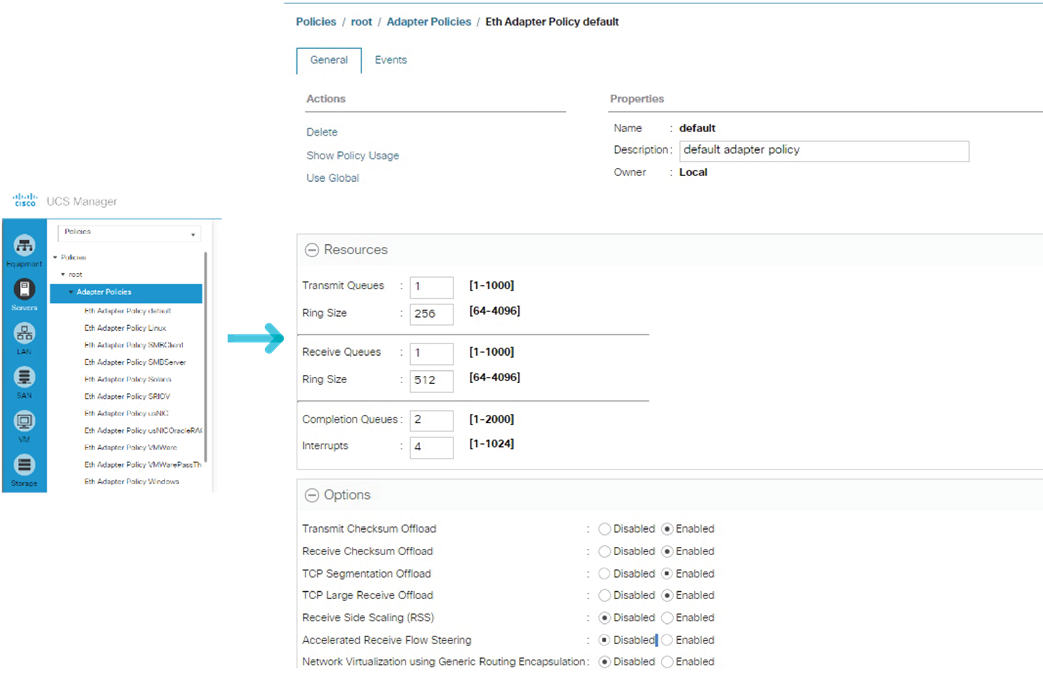
Table 2. Recommended default OS eNIC settings
| Parameter |
Default |
Microsoft Windows |
Linux |
VMware ESXi |
| Transmit (TX) settings (number of queues and ring size) |
Queues: 1
Ring size: 256
|
Queues: 1
Ring size: 256
|
Queues: 1
Ring size: 256
|
Queues: 1
Ring size: 256
|
| Receive (RX) settings (number of queues and ring size) |
Queues: 1
Ring size: 512
|
Queues: 4
Ring size: 512
|
Queues: 1
Ring size: 512
|
Queues: 1
Ring size: 512
|
| Number of completion queues (CQs) and interrupts |
CQs: 2
Interrupts: 4
|
CQs: 5
Interrupts: 8 or 512
|
CQs: 2
Interrupts: 4
|
CQs: 2
Interrupts: 4
|
| Adapter options |
TX and RX checksum, TCP segmentation offload (TSO), and large receive offload (LRO)
|
TX and RX checksum, TSO, LRO, and receive-side scaling (RSS)
|
TX and RX checksum, TSO, and LRO
|
TX and RX checksum, TSO, and LRO
|
Standalone management (rack servers)
When a Cisco UCS C-Series Rack Server is not being managed by Cisco UCS Manager, the Cisco IMC provides embedded server management and monitoring. Similar to Cisco UCS Manager, Cisco IMC provides programmatic control for several of the server components, such as BIOS settings, boot order, storage management, and vNIC settings. In addition, the parameters and settings can be configured through the Cisco IMC GUI, the CLI, or the XML API.
When a Cisco UCS C-Series Rack Server is in standalone mode, two vNICs are created by default (Figure 7), and they cannot be deleted. Up to 16 additional vNICs can be created as needed, with each vNIC having its own unique settings.
|
|
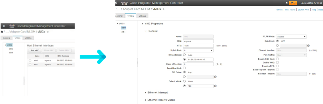
The default settings for the two initially created vNICs and for any newly created vNICs are shown in Table 3. These initial settings can be altered to better suit individual application requirements.
Table 3. Default vNIC settings
| Parameter |
Default |
| TX settings (number of queues and ring size) |
Queues: 1 Ring size: 256 |
| RX settings (number of queues and ring size) |
Queues: 4 Ring size: 512 |
| Number of CQs and interrupts |
CQs: 5 Interrupts: 8 |
| Adapter options |
TX and RX checksum, TSO, LRO, and RSS |
If multiple vNICs are using the same port interface, the bandwidth is shared equitably between the vNICs. Each vNIC can use the available bandwidth. If all the vNICs are vying for bandwidth, then bandwidth is equally divided among the vNICs. For example, if Port 0 is servicing three vNICs that are all part of the same quality-of-service (QoS) policy, each vNIC will get an equal share (33 percent) of the available bandwidth.
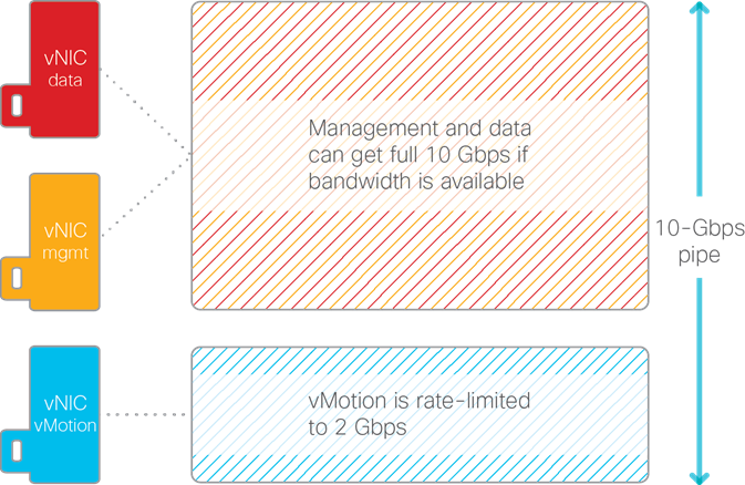
In some instances, you may want to cap the upper bandwidth limit for a particular vNIC. For example, live migration is bandwidth intensive and tends to consume as much bandwidth as is available. Although live migration is important, you may want to rate-limit vNIC traffic in hardware to cap bandwidth consumption, to help ensure that other vNIC workloads get the bandwidth they need.
In Figures 8 and 9, a rate limit is created through a QoS policy for the vNIC dedicated to live migration (VMware vMotion traffic), capping bandwidth at 2 Gbps. As a result, the vNIC can never consume more than 2 Gbps. Assuming a 10-Gbps interface, the other two vNICs (serving data and management traffic) will share the remaining 8 Gbps. If the vMotion vNIC is not active, the data and management vNICS will be able to use the full 10 Gbps of bandwidth.
|
|
|
|
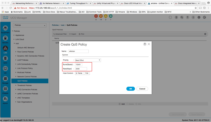
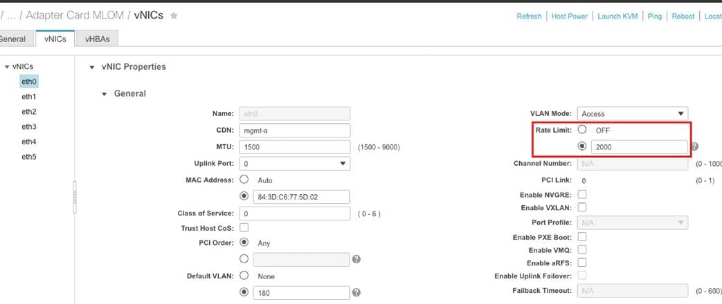
Figure 10 shows a QoS policy being instantiated for a vNIC through the Cisco IMC GUI.
|
|
The sections that follow describe a number of eNIC parameters that you can tune to optimize performance for the vNIC.
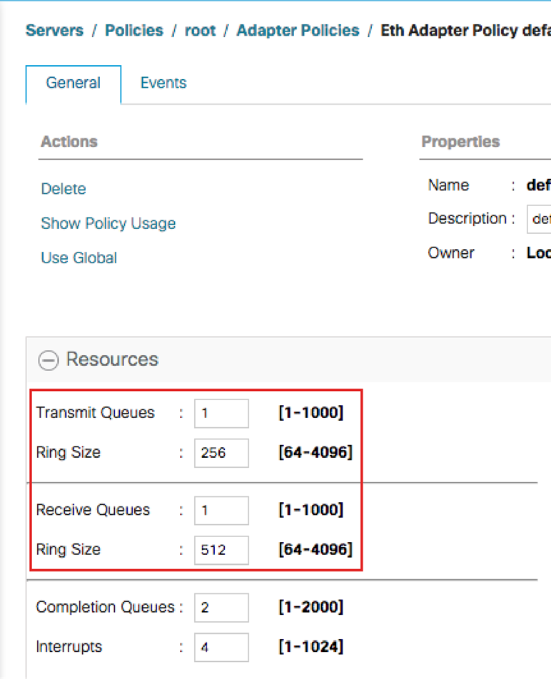
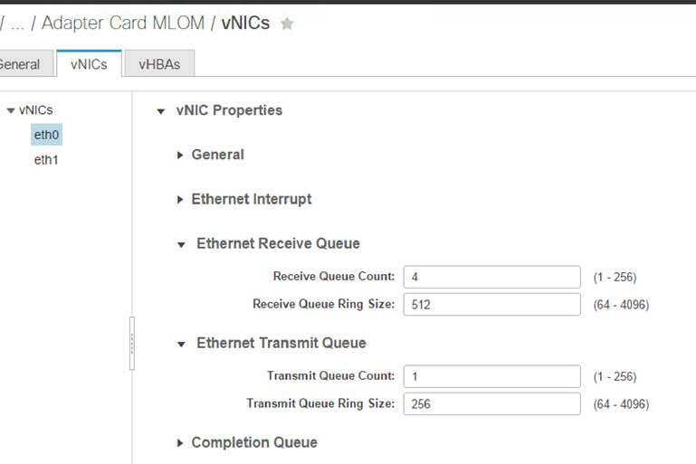
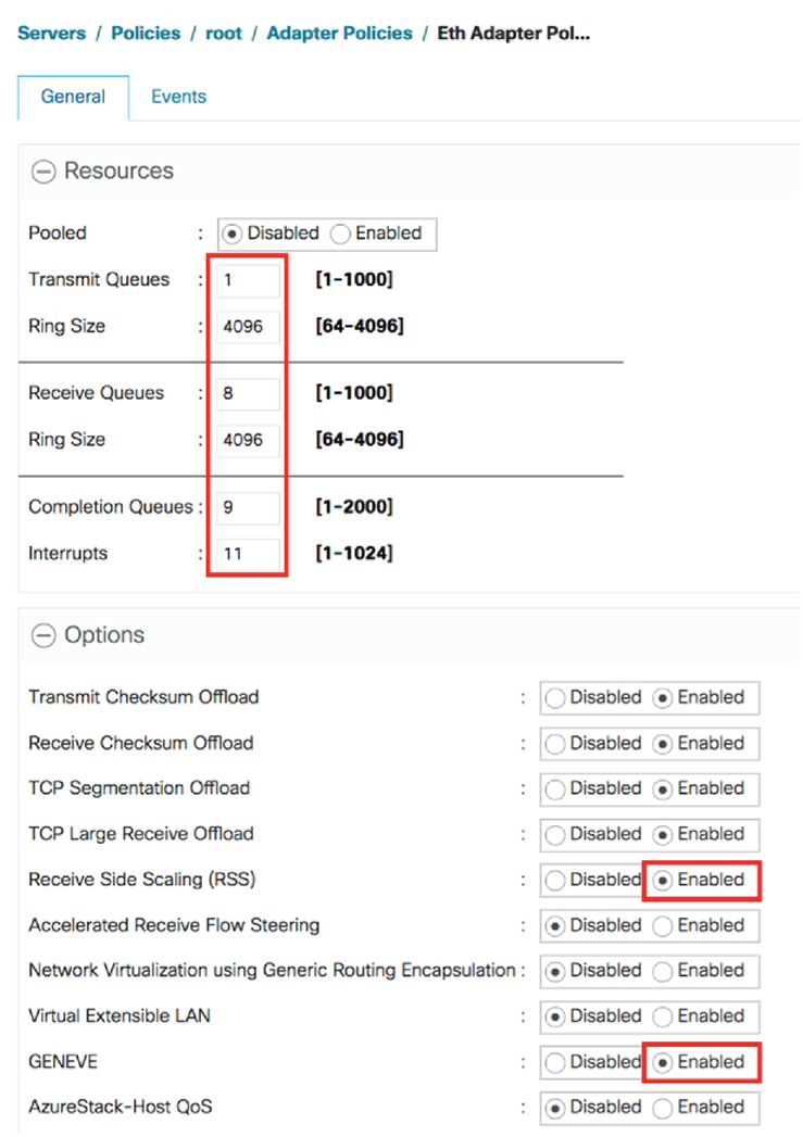
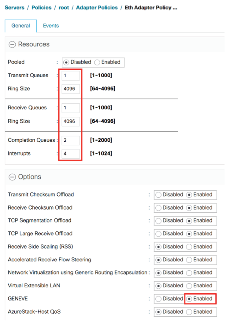
The adapter policy allows you to define the number of queues for transmit and receive traffic on a per-vNIC basis. Increasing the number of queues enables simultaneous transmit and receive packets on multiple ring queues from multiple CPU cores. The number of transmit and receive queues can be defined independent of each other. For example, a vNIC can be configured with one transmit queue and four receive queues. Figures 11 and 12 show transmit and receive queue count and ring size configurations using Cisco UCS Manager and Cisco IMC respectively.
|
|
|
Note: If you configure more than one receive queue, you need to enable RSS for the adapter policy.
|
The Cisco UCS VIC supports RSS, and it can be enabled on a per-vNIC basis. RSS allows the incoming traffic to be spread across multiple CPU cores. The CPU cores can then pull the packets in parallel, helping improve the overall bandwidth to the server. Figures 13 and 14 illustrate how to enable RSS using Cisco UCS Manager and Cisco IMC respectively.
|
|
|
The implementation of RSS differs slightly between Cisco UCS Manager and Cisco IMC. When RSS is enabled in Cisco UCS Manager, both IPv4 and IPv6 protocols are enabled. When RSS is enabled using Cisco IMC, protocol selection is allowed.
|
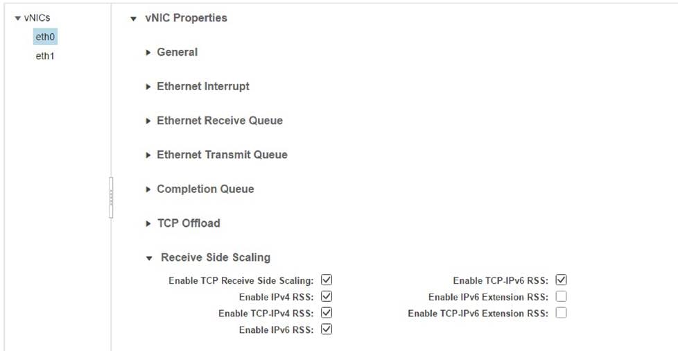
Table 4. RSS and maximum supported receive queues
| Parameteer |
Microsoft Windows |
Linux |
VMware ESXi |
| RX queue |
8 |
8 or number of CPU cores |
16 |
| RSS |
Enabled |
Enabled |
Enabled |
Transmit and receive queue sizes
The Cisco UCS VIC allows manual configuration of transmit and receive ring queue buffer descriptors on a per-vNIC basis. The default buffers are set small for lower packet latency. However, in some cases increasing the buffer size is warranted. If the network load is heavy and dropped packets are observed on the adapter interface, increasing the queue buffer can help reduce the number of dropped packets and improve overall performance.
Completion queues and interrupts
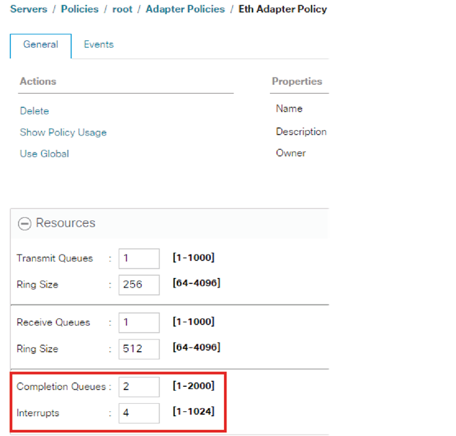
Completion queues are used to notify software of packet transmit and packet receive events. The completion queue can be dedicated to an individual transmit or receive queue. Alternatively, multiple transmit and receive queues can share a single completion queue. The vNIC uses interrupts to notify the CPU that a packet is ready to be picked up from the kernel buffer. Figures 15 and 16 show completion queue and interrupt configuration using Cisco UCS Manager and Cisco IMC respectively.
|
|
|
|
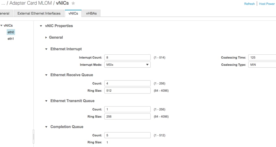
The number of completion queues and number of interrupts have a direct relationship with the number of transmit and receive queues. The number of completion queues allocated should be the sum of the transmit queues and receive queues (CQ = TXQ + RXQ). The interrupt calculation, however, varies by operating system.
● For Linux, the number of interrupts is set to “CQ + 2” for the Cisco UCS Linux enic driver version up to 3.2. For enic driver 3.2 and up the interrupt would be “(maximum of TX or RX queue) + 2.”
● For Microsoft Windows, the number of interrupts for 1200 and 1300 series VICs is “CQ + 2 rounded up to the nearest power of 2” and for the 1400 series VICs the interrupt would be at least “2x server_cpu-cores + 4” or up to a maximum of 512.
● For ESXi, the interrupt would be set as “CQ + 2”.
Table 5. Recommended default OS eNIC settings
| Parameter |
1 TX queue and 4 RX queues |
4 TX queues and 8 RX queues |
||
|
|
Linux
|
Microsoft Windows
|
Linux
|
Microsoft Windows
|
| CQ |
5
|
5
|
12
|
12
|
| Interrupt |
6 or 7
1
|
8 or 512
2
|
10 or 14
1
|
16 or 512
2
|
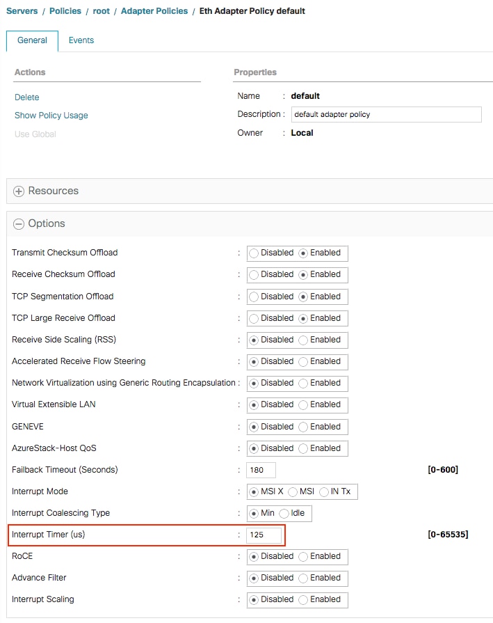
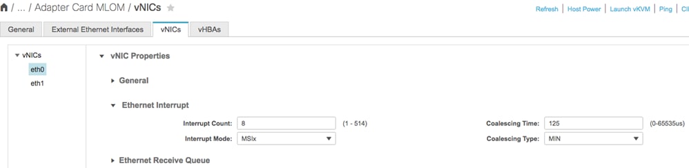
As mentioned earlier, hardware interrupts are raised to inform the CPU to either pull the packet from the receive queue or transmit the packet to the wire. The interrupt rate can be controlled with different types of wait periods. This value changes both the transmit timer and the receive timer. In most cases, the timer does not need to be adjusted. For latency-sensitive workloads or intensive transactional applications, however, lowering the rate can increase performance. However, a lower rate will also increase CPU utilization and can potentially interfere with other processes. Figures 17 and 18 show interrupt coalescing timer configuration using Cisco UCS Manager and Cisco IMC respectively.
|
|
|
|
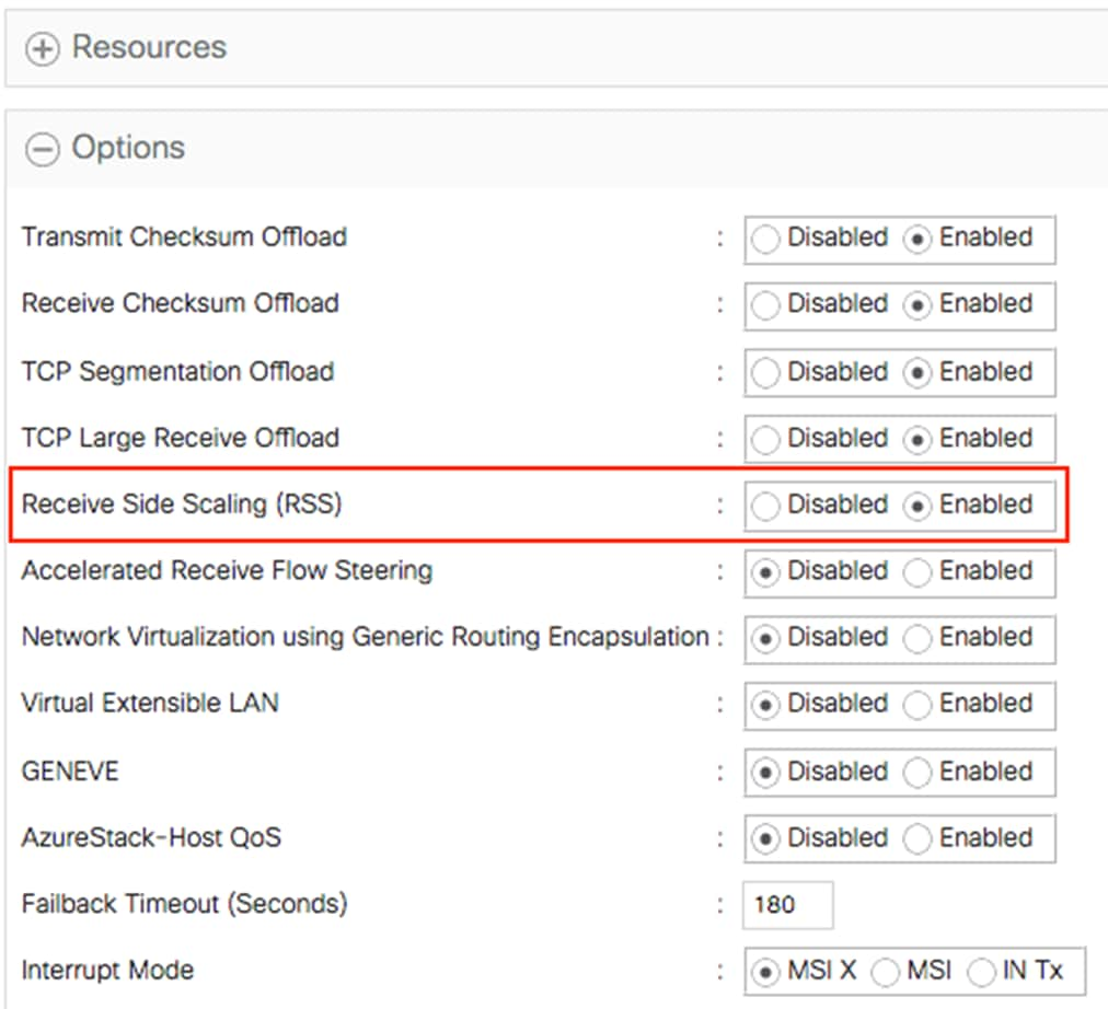
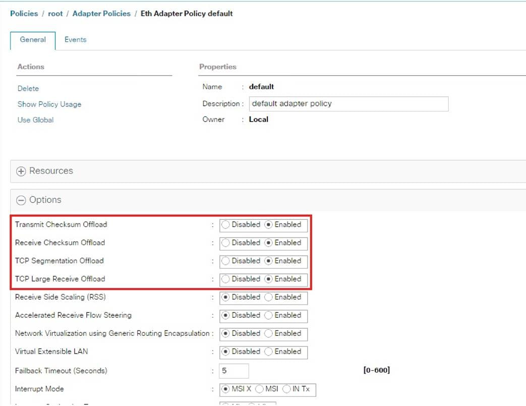
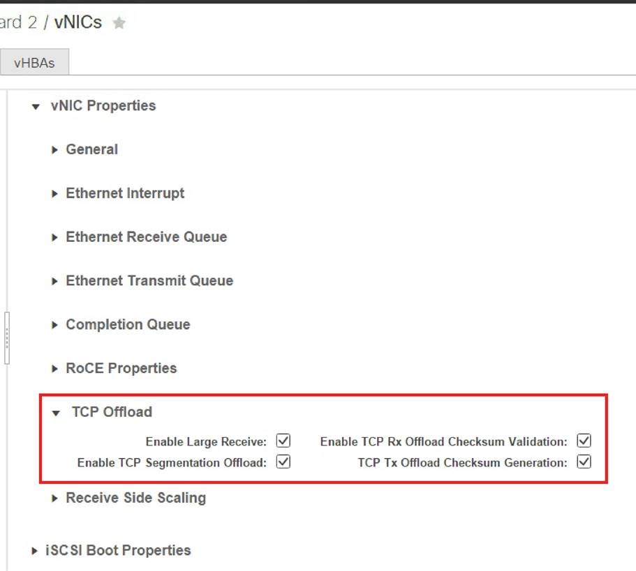
Offloading is a beneficial feature that should be enabled in almost all cases. Offloading allows the OS to take advantage of the adapter hardware to perform certain functions (Table 6), reducing the CPU processing requirements for these specific packet-level functions. By default, most of the offloads supported by the Cisco UCS VIC are enabled for both IPv4 and IPv6 packets, including transmit and receive checksum offload, TCP segmentation offload, and TCP large receive offload. Figures 19 and 20 show offload configuration using Cisco UCS Manager and Cisco IMC respectively.
|
|
|
|
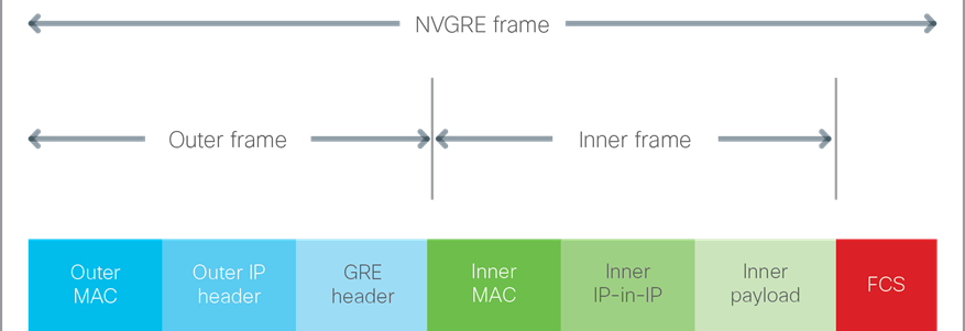
An overlay network provides agility and flexibility to system administrators, allowing them to connect both virtual and physical devices over an existing physical network. Many standards have evolved to provide this type of solution, including Virtual Extensible LAN (VXLAN), Network Virtualization using Generic Routing Encapsulation (NVGRE) and Generic Networking Virtualization Encapsulation (GENEVE). All these network overlay technologies use a tunneling technique whereby the original frame is encapsulated in an IP packet along with an extra header inserted into the overall packet. Figure 21 shows the VXLAN frame, Figure 22 shows the NVGRE frame, and Figure 23 shows the GENEVE frame. This additional header typically breaks existing offload engines, shifting the work back to the server and causing higher CPU utilization for the additional packet processing.
|
|

|
|
|
|
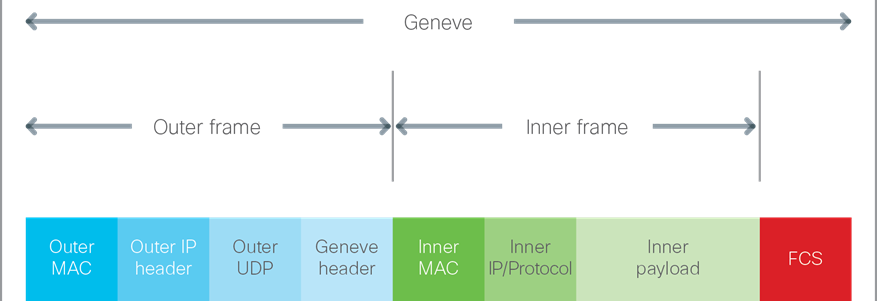
Network overlay offload is supported with the third and fourth generations of the Cisco UCS VIC (1300 and 1400 series). The overlay offload capabilities of VIC as of Cisco 4.1(3) UCS Manager and IMC releases are as follows.
● VIC 1300 supports VXLAN and NVGRE offloads
● VIC 1400 support VXLAN, NVGRE and GENEVE offloads
● VXLAN offload is supported for VMware ESXi, Linux and Microsoft Windows
● NVGRE offload is supported for Microsoft Windows
● GENEVE offload is supported for VMware ESXi.
Additionally, note that the Cisco UCS VIC 1300 Series supports VXLAN offload with only IPv4 payload while the 1400 series doesn’t have any such limitation and the Cisco UCS VIC 1400 supports VXLAN offloads with both IPv4 and IPv6 payloads. For some offload functions, the Cisco UCS VIC can process both the outer and inner headers, which reduces the overall burden on the CPU (Table 6).
Table 6. Network overlay support with offloads
| Egress (transmit) |
Outer frame |
Inner frame |
| IP checksum |
Yes |
Yes |
| TCP and User Datagram Protocol |
UDP only |
Yes |
| TSO |
- |
Yes |
| Ingress (I) |
Outer frame |
Inner frame |
| IP checksum |
Yes |
Yes |
| TCP and UDP checksum |
UDP only |
Yes |
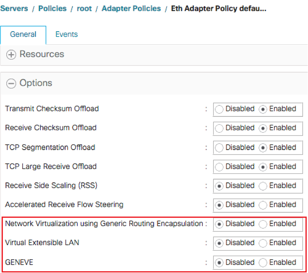
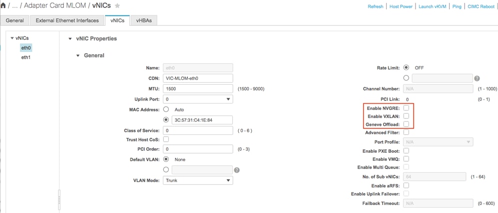
Figures 24 and 25 show how to enable network overlay offloads using Cisco UCS Manager and Cisco IMC respectively.
|
|
|
Note: You cannot enable the network overlay offload feature with Cisco NetFlow, user-space NIC (usNIC), or VMware NetQueue. Refer to the configuration guide and release notes for additional information. Cisco recommends enabling RSS with VXLAN offloads for greater network performance improvement for the server.
|
VMware NSX-T uses GENEVE tunnels, and GENEVE offload can improve its networking performance. GENEVE offload support for the VMware ESXi hypervisor with 1400 series VICs has two possible solutions depending on whether NSX-T vSwitch (N-VDS or VDS 7) is using the standard mode or Enhanced Datapath mode. The VIC has two different drivers (nenic or nenic-ens), one for each mode. ESXi automatically loads the appropriate VIC driver based on the NSX-T configuration and does not require any actions from the user.
The GENEVE offload for NSX-T vSwitch in standard mode is set up by having the user first enable multiple RX-queues with RSS and Geneve offload on the UCS adapter policy for a vNIC (Figure 26). Then, on the NSX-T manager, the user selects the standard mode for vSwitch. In this case the 1400 series VIC enables RSS on the inner packet, TSO for inner IPv4/v6 packets and TX/RX checksum offload for IPv4/v6 packets. This helps reduce the CPU utilization and in achieving higher throughput. This feature is supported from the Cisco UCS Manager and Cisco IMC release 4.1(2) and up.
|
|
Enhanced Network Stack (ENS) or alternatively Enhanced Datapath is the other option that can be turned on the VMware N-VDS or VDS 7 vSwitch. ENS borrows many techniques from the data plane development kit (DPDK) to achieve higher performance. Most notably, ENS utilizes polling to achieve high packet rates. When ENS is enabled, vSwitch uses the VMware ENS stack and utilizes the VIC ENS driver for its uplink ports.
To use ENS, the user first enables Geneve offload on the UCS adapter policy (Figure 27). Then, on the NSX-T manager, the user enables Enhanced Datapath mode on N-VDS or VDS 7. The 1400 series VIC with ENS uses single TX/RX queue, and there is no RSS support in this case. This feature is supported from Cisco UCS Manager and Cisco IMC release 4.1(3) and up.
|
|
Virtualization performance improvements
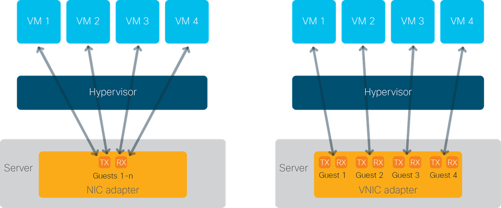
Server virtualization can provide significant benefits, allowing administrators to increase hardware utilization and more rapidly deploy applications. However, virtualization also introduces a new set of challenges, including slower network I/O performance for guest virtual machines than for bare-metal servers. The hypervisor is typically the bottleneck.
When the guest virtual machines run behind the hypervisor, all the I/O is serviced from a single transmit and receive queue, creating a bottleneck and burdening the hypervisor. The single transmit and receive queue pair limits the overall bandwidth that can flow to the guest machine because the bandwidth is being shared across all the guest machines. Moreover, the hypervisor must sort and switch the I/O traffic to the correct virtual machine.
To help reduce the burden for the hypervisor and eliminate the queue sharing, the Cisco UCS VIC can create dedicated queue pairs for guest machines running under both Microsoft Windows Hyper-V and VMware ESXi. This approach provides significant benefits. First, the transmit and receive queue pairs are no longer shared with other guest machines. Second, the hypervisor is no longer responsible for sorting and switching packets because packet steering is moved to the adapter. The adapter performs packet steering based on Layer 2 information such as MAC address and VLAN. As a result, the hypervisor is responsible only for moving the traffic between the adapter and the virtual machine. This approach improves I/O performance and frees the hypervisor for other tasks.
Note: This virtualization function is supported with the second-, third-, and fourth- generation Cisco UCS VIC 1200, 1300, and 1400 series.
The feature support across different generations of Cisco UCS VICs are as follows
● VIC 1200, 1300 and 1400 series support NetQueue for ESXi
● VIC 1300 and 1400 support virtual machine queue (VMQ) for Windows Hyper-V
● VIC 1400 support VMMQ and is recommended over VMQ for Windows Hyper-V
The Cisco UCS VIC can support up to 128 virtual machine queues (VMQs) per vNIC and a total of 256 VMQs per adapter. While the VIC hardware is capable of supporting these numbers, there are operating system specific limits. Included below are the limits per vNIC for various operating systems.
● VMware ESX 6.0 and lower: 8 VMQ
● VMware ESXi 6.5 and up: 16 VMQ
● Microsoft Windows Server Hyper-V: 64 VMQ or 64 VMMQ vPorts
Virtual machine multi-queue (VMMQ) is an enhancement to VMQ and the Cisco UCS VIC’s RSS capabilities and this is supported on the VIC 1400 series for Windows Server 2016 and up.
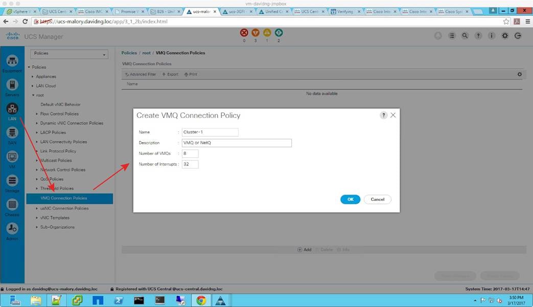
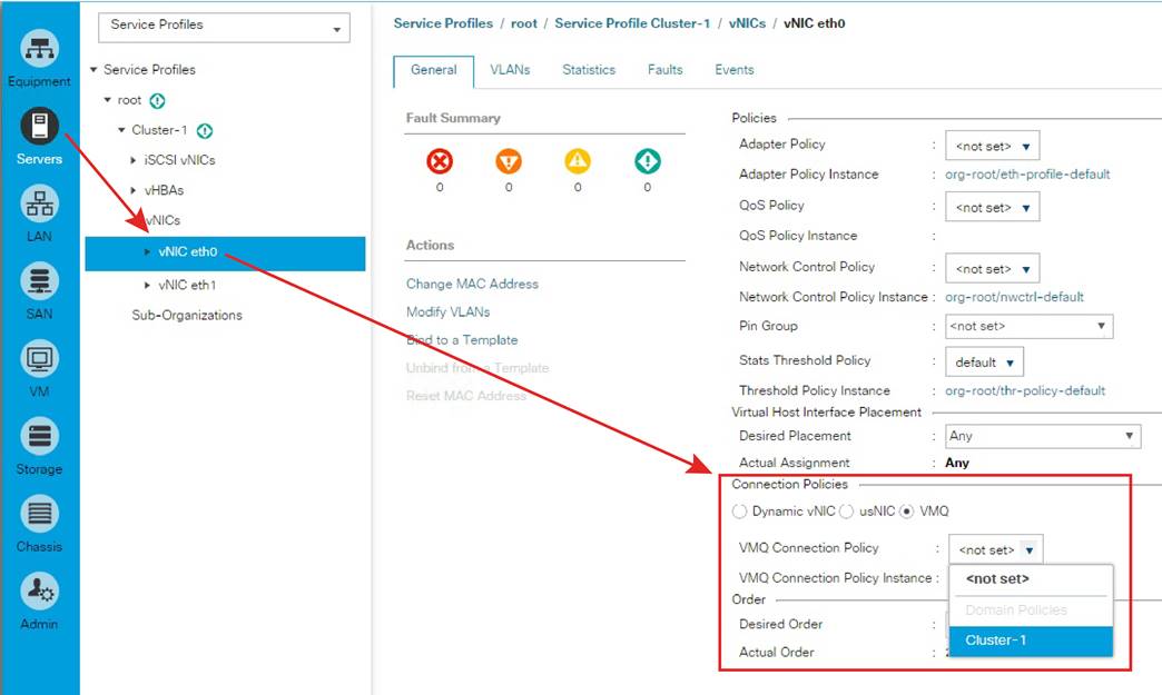
In Cisco UCS Manager, VMQ connection policy is the common configuration utility that is used to define NetQueue for ESXi and VMQ or VMMQ for Windows Hyper-V. Note that in Cisco UCS Manager and IMC, the NetQueue for ESXi is referenced as VMQ, note this when enabling this feature to avoid confusion.
Enabling these features require configuration on both the Cisco UCS VIC and the operating system, as described in the sections that follow.
|
|
Configuring VMQ connection policy with Cisco UCS Manager
Cisco UCS Manager uses the same configuration method for both Windows Hyper-V and VMware ESXi. The configuration is implemented through the VMQ connection policy and is bound to an individual vNIC profile. The connection policy is located on the LAN tab (Figure 29). Both the number of hardware queues (VMQs) and the number of interrupts can be configured. The number of VMQs essentially equals the number of guest machines being configured. Interrupts are typically set as “2 x VMQ + 2” for VMware ESXi.
For Microsoft Windows Server, VMQ is supported for 1200 and 1300 series VICs and the configurations are done from the VMQ connection policy with the number of interrupts being “2 x VMQ + 2” rounded up to the next power of 2 up to a max of 128 (Table 7). For 1400 series VICs, VMMQ is the recommended configuration and its defined by specifying the MQ policy in the VMQ connection policy.
Table 7. Sample VMQ connection policy settings
| Parameter |
4 virtual machines |
8 virtual machines |
||
|
|
Microsoft Windows
|
VMware ESXi
|
Microsoft Windows
|
VMware ESXi
|
| VMQs |
4
|
4
|
8
|
8
|
| Interrupts |
16
|
10
|
32
|
18
|
|
|
The VMQ connection policy must then be bound to the individual vNIC profile (Figure 30).
Note: When the VMQ connection policy is set, it supersedes the adapter policy.
|
|
Configuring VMQ connection policy with Cisco IMC
Configuring multiple transmit and receive queues in the Cisco IMC is different than doing so in Cisco UCS Manager, because the controller has no concept of VMQ connection policy. Instead, you need to adjust the queues (TX, RX, and CQ) and interrupts accordingly. First, you need to enable the VMQ (Figure 31).
|
|
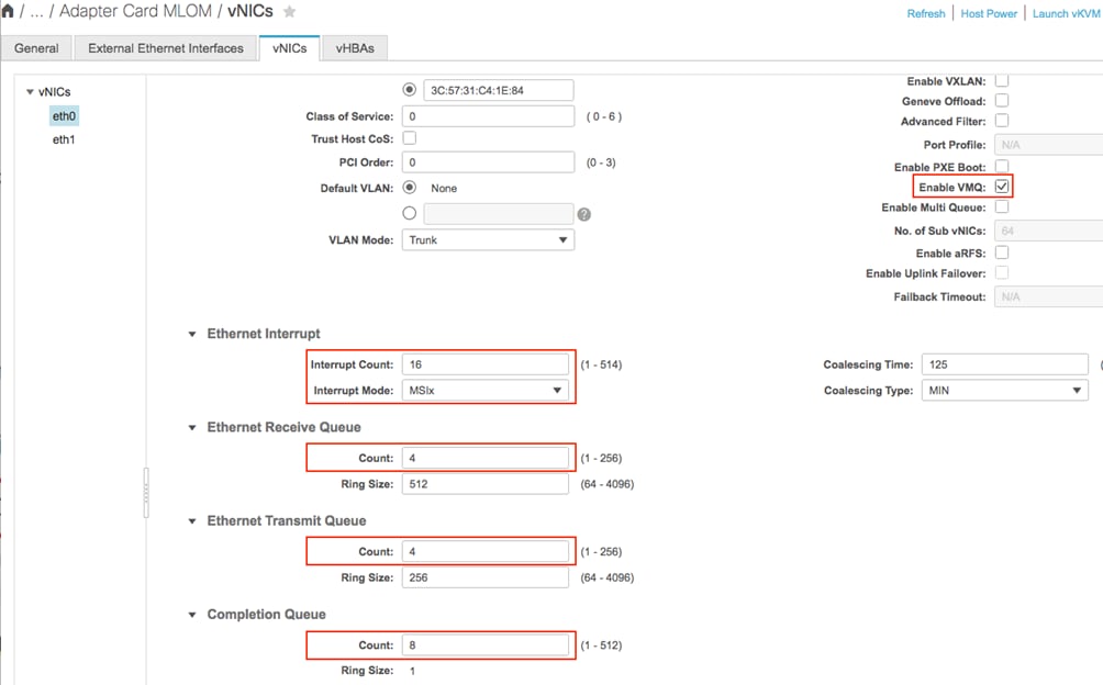
The number of transmit queues, receive queues, and completion queues should be equal to the number of virtual machines being deployed. The interrupt calculation is the same as that shown earlier for Cisco UCS Manager. The interrupt mode should also be set to message-signaled interrupt X (MSIx).
Configuring VMQ on Microsoft Windows
Several settings need to be configured on the OS side to enable VMQ. First, disable single-root I/O virtualization (SR-IOV) on the virtual switch in the Virtual Switch Manager (Figure 32).
|
|

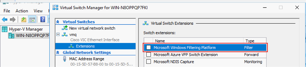
Next, for the extension for the interface, verify that the filter driver is not attached to the virtual switch (Figure 33).
|
|
|
|
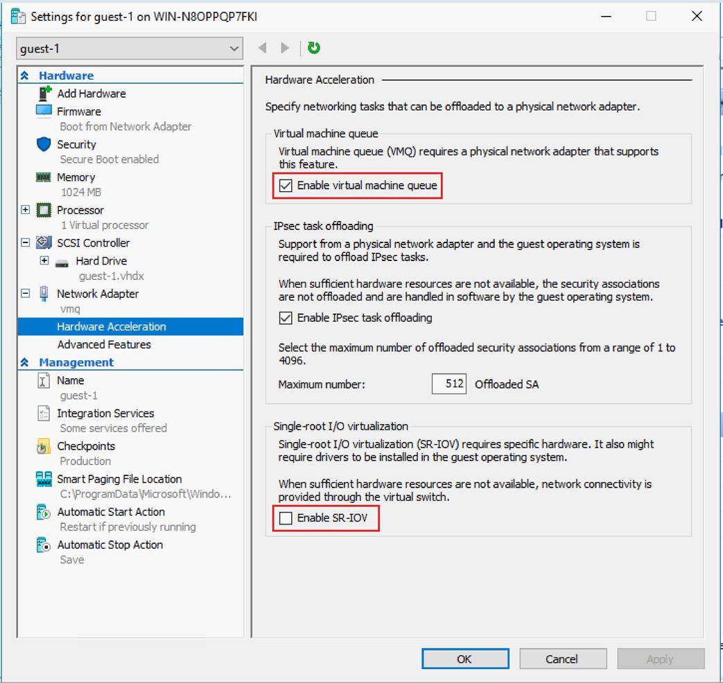
Finally, on the guest machine, check the virtual machine queue and make sure that SR-IOV is disabled (Figure 34).
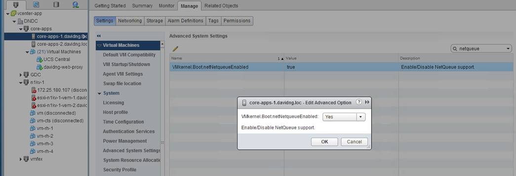
Configuring VMQ on VMware ESXi (NetQueue)
For VMware ESXi, you need to consider some scale limits. The VMware ESXi eNIC driver limits the number of VMQs to 16 per vNIC for all ESXi versions above 6.0, while for ESXi 6.0 or lower the number of VMQs supported is limited to 8 per vNIC.
To configure VMQ on VMware ESXi, verify that VMkernel.Boot.netNetqueueEnabled is set to Yes (Figure 35).
|
|
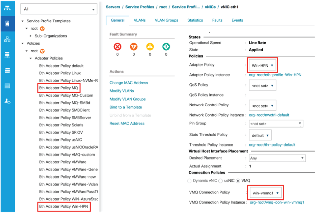
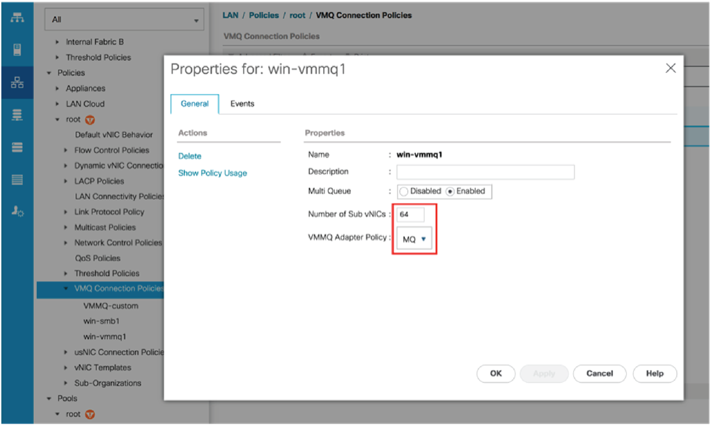
Configuring VMMQ connection policy with Cisco UCS Manager
VMMQ is supported on 1400 series VICs from Microsoft Windows Server 2016 and up. The VMMQ configuration is implemented through the VMQ connection policy and bound to a vNIC. The VMQ connection policy is located on the LAN tab (Figure 36). For VMMQ, a VMQ connection policy specifies the number of sub-vNICs or vPorts in Hyper-V and also requires a multi-queue policy which specifies the RX and TX queues and the Interrupts required for the vPorts. For ease of configuration, Cisco UCS Manager has predefined adapter-policy (“Win-HPN”) and multi-queue policy (“MQ”) which can be used for enabling 64 vPorts per vNIC.
|
|
|
|
VMMQ is also used for Microsoft Windows ROCEv2 mode 2 support on 1400 series VICs. Refer the UCS ROCE configuration guide for more details. For ROCEv2 on Microsoft Windows, use the predefined Cisco UCS Manager adapter-policy “Win-HPN-SMB” and the multi-queue policy “MQ-SMB” in the VMQ connection policy for the vNIC.
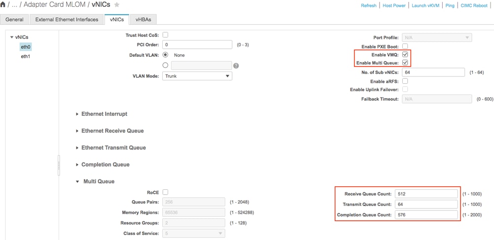
Configuring VMMQ connection policy with Cisco IMC
Configuring VMMQ on Cisco IMC involves enabling VMQ on the vNIC and configuring the multi-queue as shown below. The default configuration for the multi-queue is good for 64 vPorts or sub vNICs.
|
|
The Cisco UCS VIC can provide considerable flexibility and optimized performance for applications running on Cisco UCS rack and blade servers. Note, though, that performance can vary, and that performance tuning settings can vary from system to system and from data center to data center. You may need several iterations of testing to find the right settings for a given configuration.
Cisco Unified Computing System
Cisco UCS Manager Configuration Common Practices and Quick-Start Guide
Managing Cisco UCS C-Series Rack Servers (white paper)