Cisco Industrial Asset Vision Data Sheet
Available Languages
Bias-Free Language
The documentation set for this product strives to use bias-free language. For the purposes of this documentation set, bias-free is defined as language that does not imply discrimination based on age, disability, gender, racial identity, ethnic identity, sexual orientation, socioeconomic status, and intersectionality. Exceptions may be present in the documentation due to language that is hardcoded in the user interfaces of the product software, language used based on RFP documentation, or language that is used by a referenced third-party product. Learn more about how Cisco is using Inclusive Language.
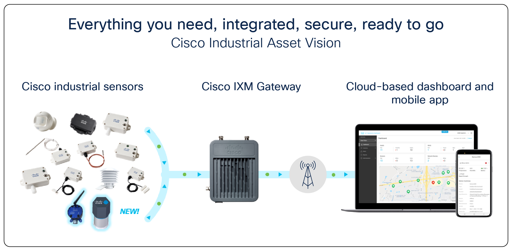
Make your organization better, safer, and more efficient by monitoring assets and facilities using Cisco Industrial Asset Vision, a simple, all-in-one, cloud-managed sensor IoT solution.
Cisco Industrial Asset Vision components
Today, data governs all aspects of business decision making, helping to improve efficiencies across the organization. But the impact of the pandemic is driving organizations to look to the Internet of Things (IoT) not just for efficiencies but also for resiliency. To adapt and thrive in the new normal, organizations need data and visibility into their operations even when no one is on the ground.
Monitoring assets and facilities using sensors helps businesses become better, safer, and more resilient. Data such as temperature, humidity, and ingress/egress all impact the status of a facility or an asset, whether it is a motor, a refrigeration unit, or even the networking gear itself. Remote monitoring helps to:
● Improve employee safety and efficiency by preventing unnecessary site visits and reducing employee movement throughout facilities
● Reduce expenses by avoiding premature equipment failure
● Improve customer satisfaction by reducing unplanned network outages and operational downtime
Cisco® Industrial Asset Vision helps to improve safety, business resiliency, and operational efficiencies by monitoring assets and facilities using sensors. It is a simple all-in-one, cloud-managed solution. Industrial Asset Vision has everything you need, from sensors to the gateways to the cloud-managed operations dashboard — integrated, secure, and ready to go.
The solution deploys in minutes using a simple QR or bar code, and scaling is designed to grow with your business. Users gain holistic and actionable insights in one easy-to-use cloud-native dashboard. The dashboard has been optimized to require minimal network expertise, thus reducing the burden on IT or the need for expensive service contracts. The dashboard provides a single view of the asset or facility health across all its associated sensors. It includes the ability to monitor health across related assets and facilities, even down to the gateway itself.
Table 1. Features and benefits
| Feature |
Benefit |
| All-in-one simple solution |
Other solutions lack integration between network, sensors, and management dashboards, causing long deployment cycles, complexity at scale, and missed insights. In contrast, Cisco Industrial Asset Vision has everything you need, including the sensors, gateways, and management capability, secure, integrated, and ready to deploy. |
| Cloud-based data operations and management dashboard |
Gain holistic and actionable insights in one easy-to-use, cloud-based dashboard. The centralized management dashboard takes the guesswork out of which sensors and gateways monitor and connect to hundreds of locations and thousands of pieces of equipment. It offers a single view of the asset or facility health across all its associated sensors. And it includes the ability to monitor and troubleshoot the gateway itself. Drill-down menus for assets, sensors, alerts, and networks help both OT and IT staff to quickly see the status and resolve issues through a comprehensive troubleshooting capability. They can set alerts or generate reports to take notification action and to better service their facilities and equipment. Using REST APIs and the defacto standard MQTT connectivity protocol, Industrial Asset Vision can share data with enterprise systems such as Enterprise Resource Planning (ERP), service management, inventory control, and analytics. User can also integrate with Azure IoT Hub. |
| Cisco sensors |
Cisco Industrial Asset Vision includes a family of industrial sensors that provide telemetry and location information for assets and facilities. They are preintegrated with the Cisco Wireless Gateway for LoRaWAN (IXM) and management dashboard. Most have IP65 and IP67 ratings, allowing them to be deployed in outdoor and industrial indoor environments. Deploy one or many to monitor a wide variety of conditions, including, humidity, leak detection, room temperature, machine temperature, product temperature, ingress and egress, lighting, occupancy, vibration and asset location. All sensors which support battery powering come with batteries and are easy to install. |
| Cyber security |
Backed by Cisco security, investment, and industry expertise, our solutions run on Cisco’s trusted networks so that your data is protected, available, and safe for you to use. |
| Easy sensor and gateway provisioning |
Provisioning and installing Cisco Industrial Asset Vision’s sensors and gateways requires minimal technical expertise. Using a mobile app and a QR code or bar code, the devices are provisioned in seconds and immediately generate either environmental, asset, or geolocation data. This dramatically improves the time to value and the ROI for these IoT projects. Scaling to thousands of sensors becomes a breeze. |
| Cisco Wireless Gateway for LoRaWAN (IXM gateway) |
Industrial Asset Vision includes support for the Cisco IXM gateway. This gateway supports LoRaWAN for wireless connectivity and, like the sensors, is designed for outdoor and industrial indoor spaces. It is ideal for use cases that require long-range wireless connectivity and extended sensor battery life. Its cost-effective ruggedized form factor makes it ideal to deploy in a variety of places. It also provides a high sensor-to-gateway ratio, making deployments very cost-effective. Asset Vision includes an RF Performance tool to help determine the coverage area at customer sites. |
| Subscription/SaaS model |
IoT solutions need implementation models that can grow and scale with enterprise business demands. After a one-time fee for the sensors and gateway hardware, customers pay a low monthly subscription fee based on the number of connected sensors. |
Cisco Industrial Asset Vision is simple, scalable, and secure
Sensors provide insights into the status of an asset or a facility, giving you the control you need to improve your operations and your business resilience without being onsite. But today, only a small portion of assets and facilities are connected with sensors. And these sensors are unreliable, unsecure, and difficult to use and scale. They lack the integration between the network, the sensors, and management, causing long deployment cycles, complexity, and missed insights. Cisco Industrial Asset Vision overcomes these challenges. It offers:
● Accelerated time to value: Sensors and networks from different vendors can lead to long testing cycles and unreliable interoperability between sensors and gateways. Cisco Industrial Asset Vision uses Cisco sensors and Cisco LoRaWAN gateways that are fully validated, resulting in simple, quick, and reliable installation and provisioning.
● Enterprise scale: Installing and triaging multivendor solutions across sensors, the network, and dashboard applications is challenging — especially at scale. Most current sensor solutions use unmanaged networks with little to no ability to make network updates remotely and securely. These limitations can heavily burden IT or require expensive service contracts to operate at scale. However, Cisco Industrial Asset Vision brings the ability to make changes and updates remotely. For organizations with geographically dispersed assets and facilities, having this capability enables scaling to any size of sensor solution deployment anywhere.
● Ability to make better and timelier decisions: Without timely and relevant insights, there is a greater risk that problems will go undetected and opportunities to improve efficiencies will be missed. The network is typically non-integrated with the rest of the solution. If there is a problem with the network, it often manifests as a problem with the asset or the sensor environment itself. With Cisco Industrial Asset Vision’s dashboard, customers need only one solution to correlate data and identify business-impacting trends.
● Cyber Security: Every sensor solution runs the risk of incurring various forms of data loss, intrusion, and malware. Since Cisco Industrial Asset Vision is built on the features and benefits of Cisco security, OT customers can be assured that their solution is running on Cisco’s trusted and managed network. The integrated solution helps reduce complexity and minimize vulnerabilities.
Table 2. Platform Support
| Product family |
Platforms supported |
| LoRaWAN gateway |
Cisco IXM 900 MHz Cisco IXM 800 MHz |
| LoRaWAN sensors |
AV200, AV201, AV202, AV203 AV204, AV205, AV206, AV207 AV250, AV251, AV300, AV400 |
| Cloud application |
Cisco IOT Operations Dashboard |
| Mobile Application |
Apple IOS, Android |
Cisco Industrial Asset Vision subscription is purchased and licensed using the IOTAV-BUNDLE-US, IOTAV-BUNDLE-EU, IOTAV-BUNDLE-AU and IOTAV-BUNDLE-IN Multiline Bundle (MLB).
Table 3. Multiline bundles
| Part number |
Description |
Geography or region |
| IOTAV-BUNDLE-US |
Industrial Asset Vision Bundle (1yr, 3yr, or 5yr) |
United States and Canada (US915) |
| IOTAV-BUNDLE-EU |
Industrial Asset Vision Bundle (1yr, 3yr, or 5yr) |
Europe (EU868) |
| IOTAV-BUNDLE-AU |
Industrial Asset Vision Bundle (1yr, 3yr, or 5yr) |
Australia, New Zealand, Brazil, Argentina and Chile (AU915) |
| IOTAV-BUNDLE-IN |
Industrial Asset Vision Bundle (1yr, 3yr, or 5yr) |
India (IN865) |
Industrial Asset Vision includes a portfolio of sensor in two categories: location tracking and condition monitoring. Sensor product specifications are detailed below.
Product specifications for the Cisco LoRaWAN IXM gateway may be found at this link.
1. AV200: Outdoor Temperature and Humidity Sensor
Solution overview
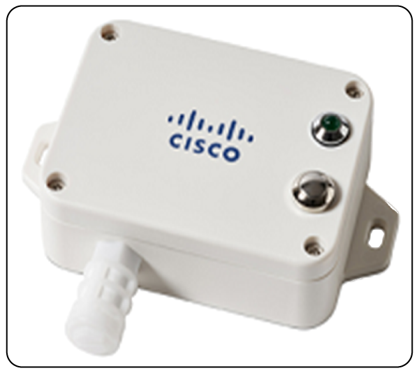
The AV200 is an outdoor temperature and humidity sensor for use with Cisco Industrial Asset Vision. Data from the sensor is communicated via the LoRaWAN protocol.
Product image
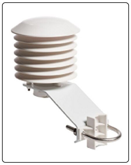
AV200 Outdoor Temperature and Humidity Sensor
Key benefits
● Temperature and humidity detection
Product details
Table 4. Cisco part number
| Geography |
Cisco PID |
| US, Canada |
IOTAV-L-ENV-O1-US |
| Europe |
IOTAV-L-ENV-O1-EU |
| Australia, New Zealand, Brazil, Argentina, Chile |
IOTAV-L-ENV-O1-AU |
| India |
IOTAV-L-ENV-O1-IN |
Table 5. Environmental/Physical specifications
| Specification |
Description |
| Operating Temperature |
-20 to 55°C (-4 to 131°F) |
| Storage Temperature |
-40 to 85°C (-40 to 185°F) |
| Operating Humidity |
<90% RH (No Condensation) |
| IP Rating |
IP54 |
| Dimensions (L x W x H) |
222 x 130 x 195 mm (8.74 x 5.11 x 7.67 inches) |
Table 6. Radio
| Specification |
Description |
| Frequency Band |
800 MHz / 900 MHz ISM Band |
| Transmit power (conducted) |
US915: 20 dBm EU868: 16 dBm AU915: 20 dBm IN865: 20 dBm |
| Rx Sensitivity |
-136dBm (SF12) |
| Range |
Up to 10km (dependent on environment) |
Table 7. Measurements
| Specification |
Description |
| Temperature Measurement Range |
-20 to 55°C (-4 to 131 °F) |
| Temperature Accuracy |
+/- 1.5°C @ 25°C |
| Humidity Measurement Range |
0% RH to 100% RH |
| Humidity Accuracy |
+/- 10% RH @ 25°C |
| Battery Voltage Accuracy |
+/- 0.1V |
Table 8. Battery
| Specification |
Description |
| Battery Type |
2x 1.5V AA in series |
| Operating Voltage |
2.3V to 3V |
| Battery Life |
4 years |
Table 9. Reporting metrics
| Monitoring |
Default Reporting Interval |
Expected Battery Life* |
| Temperature, Humidity, Battery |
60 mins |
4 years |
Table 10. Product certification and compliance
| Specification |
Applicable regions |
| Safety |
|
| UL/CSA 60950-1/62368-1 |
North America |
| EN 60950-1/62368-1 |
EU |
| CB to IEC 60950-1 |
Worldwide |
| CB to IEC 62368-1 |
Worldwide |
| IEC 60529 (IP54) |
Worldwide |
| IEC 60950-22 |
Worldwide |
| EMC Immunity |
|
| EN 301489-1 |
EU |
| EN 301489-3 |
EU |
| Radio |
|
| EU 863-870 (EU) |
|
| EN 300220-1 |
EU |
| EN 300220-2 |
EU |
| CE RED |
EU |
| US 902-928 (USA, Canada) |
|
| FCC 47CFR Part 15 B and C |
USA |
| RSS210 |
Canada |
| IC ICES-003 |
Canada |
| AUS915 (LATAM, AU, NZ) |
|
| RCM approval |
Australia, New Zealand |
| Anatel certification1 |
Brazil |
| Enacom certification |
Argentina |
| IN865 (India) |
|
| WPC certification |
India |
| Other |
|
| RoHS |
EU |
| FCC Part 2 |
USA |
| RSS 102 |
Canada |
Wireless statement
● Este equipamento não tem direito à proteção contra interferência prejudicial e não podecausar interferência em sistemas devidamente autorizados.
● This equipment is not entitled to protection against harmful interference and may not causeinterference in properly authorized systems.
EMC CISPR statement
● Este produto não é apropriado para uso em ambientes domésticos, pois poderá causarinterferências eletromagnéticas que obrigam o usuário a tomar medidas necessárias para minimizarestas interferências.
● This product is not suitable for use in a domestic environment as it may cause electromagneticinterference that requires the user to take necessary actions to minimize such interference.
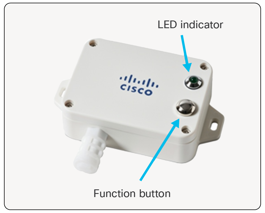
Turning AV200 On/Off
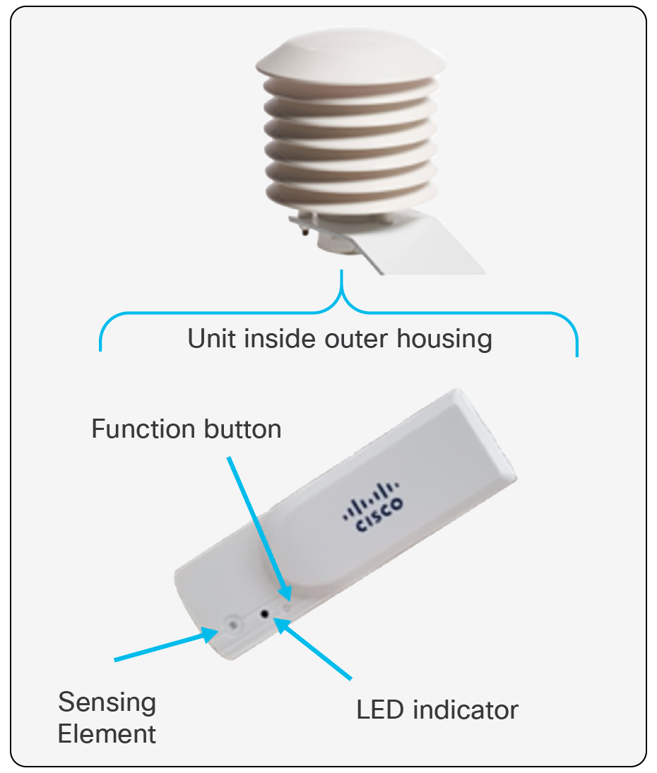
Turning AV200 On/Off
● Press and hold the Function button until…
◦ LED blinks 20 times:
◦ Sensor has been turned off.
◦ LED illuminates solid for one second:
◦ Sensor has been turned on.
◦ Sensor attempts to register with the network server.
◦ Another blink of the LED indicates that sensor has joined properly (usually happens within 30 seconds).
◦ Allow about 10 seconds after turning off before turning on.
● Once sensor has joined:
◦ Manual uplink message can be initiated with a short press of the Function button.
◦ LED will flash to indicate that message has been triggered.
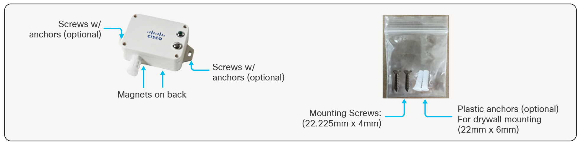
Mounting Accessories and Methods AV200
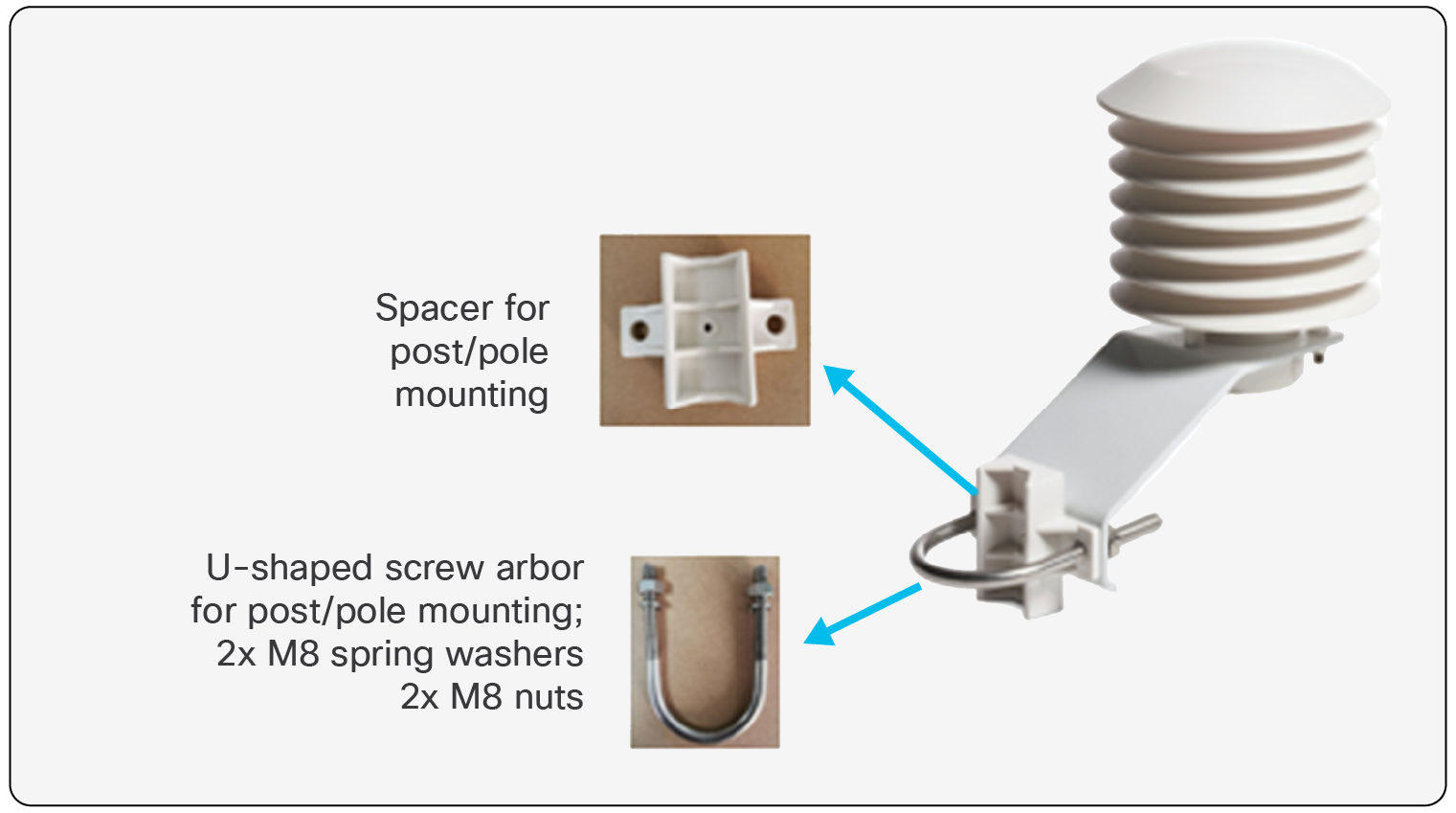
Mounting Accessories and Methods AV200
● Pole/Post Mounting via included spacer and U-bolt assembly.
◦ Pole/Post size: 25-50mm.
2. AV201: Indoor Temperature and Humidity Sensor
Solution overview
The AV201 is a LoRaWAN sensor which detects ambient air temperature and humidity. It is intended for use with Cisco Industrial Asset Vision.
Product image
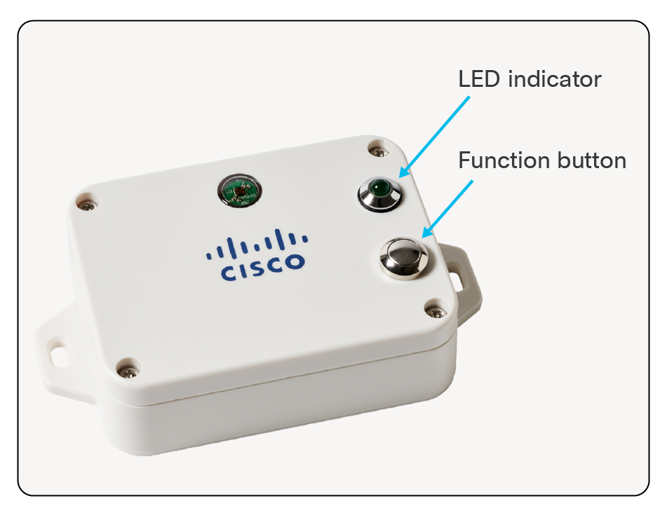
AV201 Indoor Temperature and Humidity Sensor
Key benefits
● Indoor Temperature and Humidity Monitoring
● Useful in Smart Buildings, factories, warehouses, and Smart Offices
Product details
Table 11. Cisco part number
| Geography |
Cisco PID |
| US, Canada |
IOTAV-L-ENV-I1-US |
| Europe |
IOTAV-L-ENV-I1-EU |
| Australia, New Zealand, Brazil, Argentina, Chile |
IOTAV-L-ENV-I1-AU |
| India |
IOTAV-L-ENV-I1-IN |
Table 12. Environmental/Physical specifications
| Specification |
Description |
| Operating Temperature |
-20 to 55°C (-4 to 131 °F) |
| Storage Temperature |
-40 to 85°C (-40 to 185 °F) |
| Operating Humidity |
<90% RH (No Condensation) |
| IP Rating |
IP65 |
| Dimensions (L x W x H) |
112 x 65 x 28 mm (4.4 x 2.5 x 1.1 inches) |
| Weight |
141 g (0.31 lbs) |
Table 13. Radio
| Specification |
Description |
| Frequency Band |
800 MHz / 900 MHz ISM Band |
| Transmit power (conducted) |
US915: 20 dBm EU868: 16 dBm AU915: 20 dBm IN865: 20 dBm |
| Rx Sensitivity |
-136dBm (SF12) |
| Range |
Up to 10km (dependent on environment) |
Table 14. Measurements
| Specification |
Description |
| Temperature Measurement Range |
-20 to 55°C (-4 to 131 °F) |
| Temperature Accuracy |
+/- 1°C@ 25 °C |
| Humidity Measurement Range |
0% RH to 100% RH |
| Humidity Accuracy |
+/- 4% RH @ 25 °C |
| Battery Voltage Accuracy |
+/- 0.1V |
Table 15. Battery
| Specification |
Description |
| Battery Type |
2x 3.6V ER14505 AA in parallel |
| Operating Voltage |
3.1V to 3.65V |
| Battery Life |
5 years |
Table 16. Reporting metrics
| Monitoring |
Default Reporting Interval |
Expected Battery Life* |
| Temperature, Humidity, Battery |
15 mins |
5 years |
Table 17. Product certification and compliance
| Specification |
Applicable regions |
| Safety |
|
| UL/CSA 60950-1/62368-1 |
North America |
| EN 60950-1/62368-1 |
EU |
| CB to IEC 60950-1 |
Worldwide |
| CB to IEC 62368-1 |
Worldwide |
| IEC 60529 (IP65) |
Worldwide |
| IEC 60950-22 |
Worldwide |
| EMC Immunity |
|
| EN 301489-1 |
EU |
| EN 301489-3 |
EU |
| Radio |
|
| EU 863-870 (EU) |
|
| EU 863-870 |
EU |
| EN 300220-1 |
EU |
| EN 300220-2 |
EU |
| CE RED |
EU |
| US 902-928 (USA, Canada) |
|
| FCC 47CFR Part 15 B and C |
USA |
| RSS210 |
Canada |
| IC ICES-003 |
Canada |
| AUS915 (LATAM, AU, NZ) |
|
| RCM approval AS/NZS4268 |
Australia, New Zealand |
| Anatel certification1 |
Brazil |
| Enacom certification |
Argentina |
| IN865 (India) |
|
| WPC certification |
India |
| Other |
|
| RoHS |
EU |
| FCC Part 2 |
USA |
| RSS 102 |
Canada |
Wireless statement
● Este equipamento não tem direito à proteção contra interferência prejudicial e não podecausar interferência em sistemas devidamente autorizados.
● This equipment is not entitled to protection against harmful interference and may not causeinterference in properly authorized systems.
EMC CISPR statement
● Este produto não é apropriado para uso em ambientes domésticos, pois poderá causarinterferências eletromagnéticas que obrigam o usuário a tomar medidas necessárias para minimizarestas interferências.
● This product is not suitable for use in a domestic environment as it may cause electromagneticinterference that requires the user to take necessary actions to minimize such interference.
Turning AV201 On/Off
Turning AV201 On/Off
● Press and hold the Function button for 3-5 seconds until…
◦ LED blinks 20 times:
◦ Sensor has been turned off.
◦ LED illuminates solid for a few seconds:
◦ Sensor has been turned on.
◦ Sensor attempts to register with the network server.
◦ Another blink of the LED indicates that sensor has joined properly (usually happens within 30 seconds).
◦ Allow about 10 seconds after turning off before turning on.
● Once sensor has joined:
◦ Manual uplink message can be initiated with a short press of the Function button.
◦ LED will flash to indicate that message has been triggered.
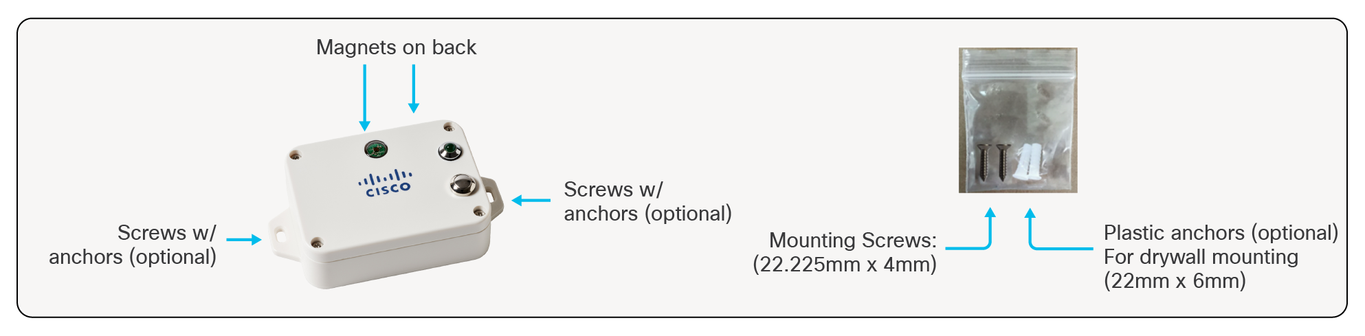
Mounting Accessories and Methods AV201
Mounting Accessories and Methods AV201
● Magnetic mount to ferromagnetic surfaces.
● Screws for attaching to walls and other flat surfaces.
◦ Package also includes plastic anchors for installation into material such as drywall/sheetrock.
● Double-sided tape (not included).
3. AV202: Product Temperature Sensor
Solution overview
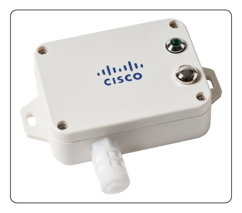
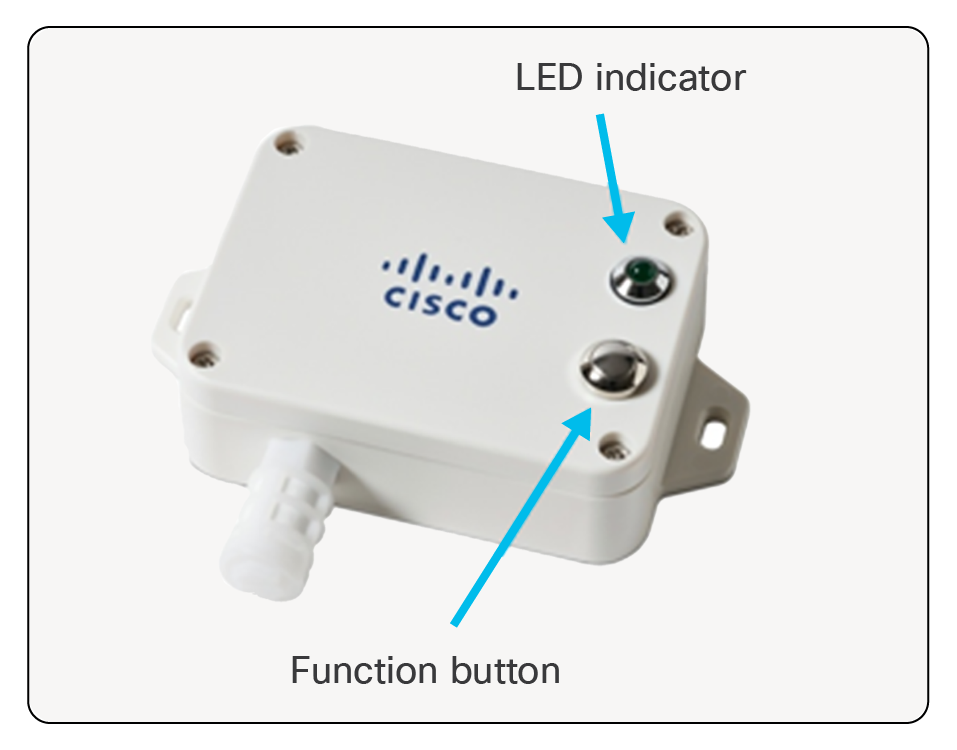
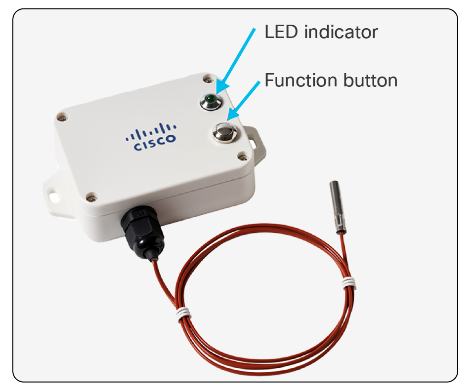
The AV202 is a LoRaWAN product temperature sensor with an external platinum probe. It is intended for use with Cisco Industrial Asset Vision.
Product image
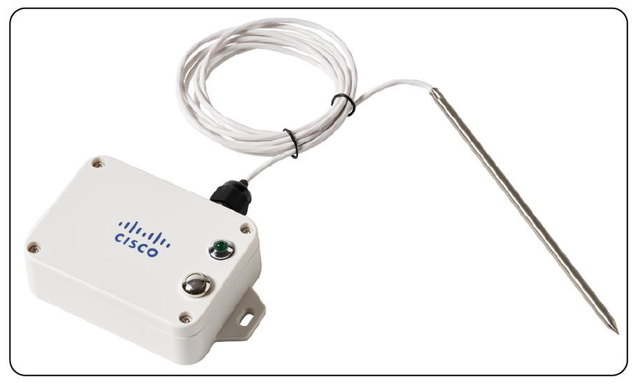
AV202 Product Temperature Sensor
Key benefits
● Temperature measuring for liquid, vapor, grain, and solid plane surfaces
Product details
Table 18. Cisco part number
| Geography |
Cisco PID |
| US, Canada |
IOTAV-L-PTM-I1-US |
| Europe |
IOTAV-L-PTM-I1-EU |
| Australia, New Zealand, Brazil, Argentina, Chile |
IOTAV-L-PTM-I1-AU |
| India |
IOTAV-L-PTM-I1-IN |
Table 19. Environmental/Physical specifications
| Specification |
Description |
| Operating Temperature |
-20 to 55°C (-4 to 131 °F) |
| Storage Temperature |
-40 to 85°C (-40 to 185 °F) |
| Operating Humidity |
<90% RH (No Condensation) |
| IP Rating |
IP65 |
| Dimensions (L x W x H) |
112 x 88.19 x 32 mm (4.4 x 3.4 x 1.25 inches) |
| Weight |
141 g (0.31 lbs) |
| Probe Material |
316 Stainless Steel |
| Probe Dimensions |
5mm (diameter); 15cm long (pointed) |
| Probe Lead Length |
2m |
Table 20. Radio
| Specification |
Description |
| Frequency Band |
800 MHz / 900 MHz ISM Band |
| Transmit power (conducted) |
US915: 20 dBm EU868: 16 dBm AU915: 20 dBm IN865: 20 dBm |
| Rx Sensitivity |
-136dBm (SF12) |
| Range |
Up to 10km (dependent on environment) |
Table 21. Measurements
| Specification |
Description |
| External PT1000 probe temperature range |
-40 to 200°C (-40 to 392 °F) |
| Temperature Accuracy |
(Assume base unit is @ 0°C ≤ t ≤ 55°C) Probe @ 0°C ≤ t ≤ 55°C: +/- 0.5°C Probe @ -40°C ≤ t < 0°C: +/- {(0.15 + 0.002* |t|) + 1} °C Probe @ 55°C < t ≤ 200°C: +/- {(0.15 + 0.002* |t|) + 0.3} °C |
| Battery Voltage Accuracy |
+/- 0.1V |
Table 22. Battery
| Specification |
Description |
| Battery Type |
2x 3.6V ER14505 AA in parallel |
| Operating Voltage |
3.1V to 3.65V |
| Battery Life |
5 years |
Table 23. Reporting metrics
| Monitoring |
Default Reporting Interval |
Expected Battery Life* |
| Temperature, Battery |
15 mins |
5 years |
Table 24. Product certification and compliance
| Specification |
Applicable regions |
| Safety |
|
| UL/CSA 60950-1/62368-1 |
North America |
| EN 60950-1/62368-1 |
EU |
| CB to IEC 62368-1 |
Worldwide |
| CB to IEC 60950-1 |
Worldwide |
| IEC 60529 (IP65) |
Worldwide |
| IEC 60950-22 |
Worldwide |
| EMC Immunity |
|
| EN 301489-1 |
EU |
| EN 301489-3 |
EU |
| Radio |
|
| EU 863-870 (EU) |
|
| EN300220-1 |
EU |
| EN300220-2 |
EU |
| CE RED |
EU |
| US 902-928 (USA, Canada) |
|
| FCC 47CFR Part 15 B and C |
USA |
| RSS210 |
Canada |
| IC ICES-003 |
Canada |
| AUS915 (LATAM, AU, NZ) |
|
| RCM approval |
Australia, New Zealand |
| Anatel certification1 |
Brazil |
| Enacom certification |
Argentina |
| IN865 (India) |
|
| WPC certification |
India |
| Other |
|
| RoHS |
EU |
| FCC Part 2 |
USA |
| RSS 102 |
Canada |
Wireless statement
● Este equipamento não tem direito à proteção contra interferência prejudicial e não podecausar interferência em sistemas devidamente autorizados.
● This equipment is not entitled to protection against harmful interference and may not causeinterference in properly authorized systems.
EMC CISPR statement
● Este produto não é apropriado para uso em ambientes domésticos, pois poderá causarinterferências eletromagnéticas que obrigam o usuário a tomar medidas necessárias para minimizarestas interferências.
● This product is not suitable for use in a domestic environment as it may cause electromagneticinterference that requires the user to take necessary actions to minimize such interference.
Turning AV202 On/Off
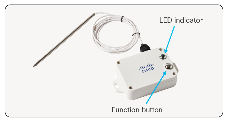
Turning AV202 On/Off
● Press and hold the Function button for 3-5 seconds until…
◦ LED blinks 20 times:
◦ Sensor has been turned off.
◦ LED illuminates solid for a few seconds:
◦ Sensor has been turned on.
◦ Sensor attempts to register with the network server.
◦ Another blink of the LED indicates that sensor has joined properly (usually happens within 30 seconds).
◦ Allow about 10 seconds after turning off before turning on.
● Once sensor has joined:
◦ Manual uplink message can be initiated with a short press of the Function button.
◦ LED will flash to indicate that message has been triggered.
Mounting Accessories and Methods AV202
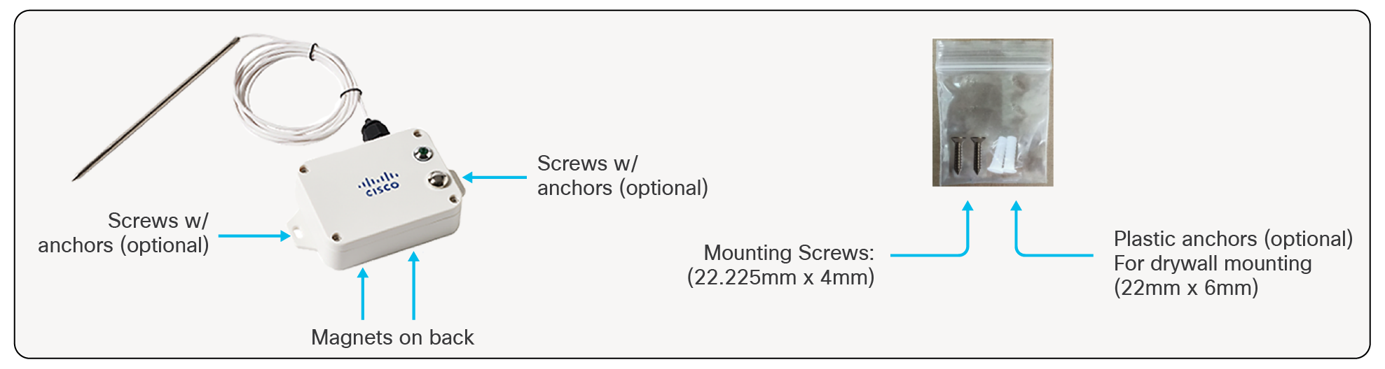
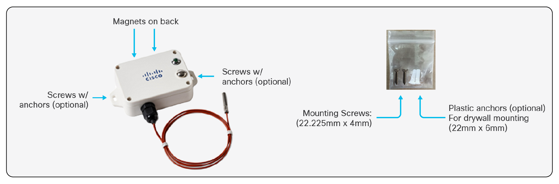
Mounting Accessories and Methods AV202
● Magnetic mount to ferromagnetic surfaces.
● Screws for attaching to walls and other flat surfaces.
◦ Package also includes plastic anchors for installation into material such as drywall/sheetrock.
● Double-sided tape (not included).
4. AV203: Refrigerator Temperature and Humidity Sensor
Solution overview
The AV203 is a LoRaWAN sensor used to measure the temperature and humidity in low temperature environments such as freezers. It is intended for use with Cisco Industrial Asset Vision.
Product image
AV203 Refrigerator Temperature and Humidity Sensor
Key benefits
● Domestic and Commercial Refrigerators
● Cold Chain Logistics
● Data Logger
Product details
Table 25. Cisco part number
| Geography |
Cisco PID |
| US, Canada |
IOTAV-L-FRZ-O1-US |
| Europe |
IOTAV-L-FRZ-O1-EU |
| Australia, New Zealand, Brazil, Argentina, Chile |
IOTAV-L-FRZ-O1-AU |
| India |
IOTAV-L-FRZ-O1-IN |
Table 26. Environmental/Physical specifications
| Specification |
Description |
| Operating Temperature |
-40 to 55°C (-40 to 131 °F) |
| Storage Temperature |
-40 to 85°C (-40 to 185 °F) |
| Operating Humidity |
<90% RH (No Condensation) |
| IP Rating |
IP65 |
| Dimensions (L x W x H) |
112 x 65 x 28 mm (4.4 x 2.5 x 1.1 inches) |
| Weight |
141 g (0.31 lbs) |
Table 27. Radio
| Specification |
Description |
| Frequency Band |
800 MHz / 900 MHz ISM Band |
| Transmit power (conducted) |
US915: 20 dBm EU868: 16 dBm AU915: 20 dBm IN865: 20 dBm |
| Rx Sensitivity |
-136dBm (SF12) |
| Range |
Up to 10km (dependent on environment) |
Table 28. Measurements
| Specification |
Description |
| Temperature Measurement Range |
-40 to 55°C (-40 to 131 °F) |
| Temperature Accuracy |
+/- 0.5°C@ 25 °C |
| Humidity Measurement Range |
0% RH to 100% RH |
| Humidity Accuracy |
+/- 3% RH @ 25 °C |
| Battery Voltage Accuracy |
+/- 0.1V |
Table 29. Battery
| Specification |
Description |
| Battery Type |
2x 3.6V ER14505 AA in parallel |
| Operating Voltage |
3.1V to 3.65V |
| Battery Life |
5 years |
Table 30. Reporting metrics
| Monitoring |
Default Reporting Interval |
Expected Battery Life* |
| Temperature, Humidity, Battery |
15 mins |
5 years |
Table 31. Product certification and compliance
| Specification |
Applicable regions |
| Safety |
|
| UL/CSA 60950-1/62368-1 |
North America |
| EN 60950-1/62368-1 |
EU |
| CB to IEC 60950-1 |
Worldwide |
| CB to IEC 62368-1 |
Worldwide |
| IEC 60529 (IP65) |
Worldwide |
| IEC 60950-22 |
Worldwide |
| EMC Immunity |
|
| EN 301489-1 |
EU |
| EN 301489-3 |
EU |
| Radio |
|
| EU 863-870 (EU) |
|
| EN 300220-1 |
EU |
| EN 300220-2 |
EU |
| CE RED |
EU |
| US 902-928 (USA, Canada) |
|
| FCC 47CFR Part 15 B and C |
USA |
| RSS210 |
Canada |
| IC ICES-003 |
Canada |
| AUS915 (LATAM, AU, NZ) |
|
| RCM approval AS/NZS4268 |
Australia, New Zealand |
| Anatel certification1 |
Brazil |
| Enacom certification |
Argentina |
| IN865 (India) |
|
| WPC certification |
India |
| Other |
|
| RoHS |
EU |
| FCC Part 2 |
USA |
| RSS 102 |
Canada |
Wireless statement
● Este equipamento não tem direito à proteção contra interferência prejudicial e não podecausar interferência em sistemas devidamente autorizados.
● This equipment is not entitled to protection against harmful interference and may not causeinterference in properly authorized systems.
EMC CISPR statement
● Este produto não é apropriado para uso em ambientes domésticos, pois poderá causarinterferências eletromagnéticas que obrigam o usuário a tomar medidas necessárias para minimizarestas interferências.
● This product is not suitable for use in a domestic environment as it may cause electromagneticinterference that requires the user to take necessary actions to minimize such interference.
Turning AV203 On/Off
Turning AV203 On/Off
● Press and hold the Function button for 3-5 seconds until…
◦ LED blinks 20 times:
◦ Sensor has been turned off.
◦ LED illuminates solid for a few seconds:
◦ Sensor has been turned on.
◦ Sensor attempts to register with the network server.
◦ Another blink of the LED indicates that sensor has joined properly (usually happens within 30 seconds).
◦ Allow about 10 seconds after turning off before turning on.
● Once sensor has joined:
◦ Manual uplink message can be initiated with a short press of the Function button.
◦ LED will flash to indicate that message has been triggered.
Mounting Accessories and Methods AV203
Mounting Accessories and Methods AV203
● Magnetic mount to ferromagnetic surfaces.
● Screws for attaching to walls and other flat surfaces.
◦ Package also includes plastic anchors for installation into material such as drywall/sheetrock.
● Double-sided tape (not included).
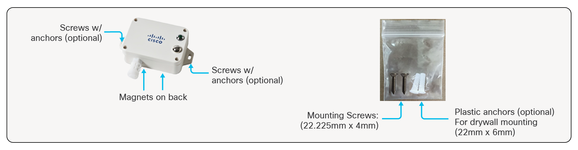
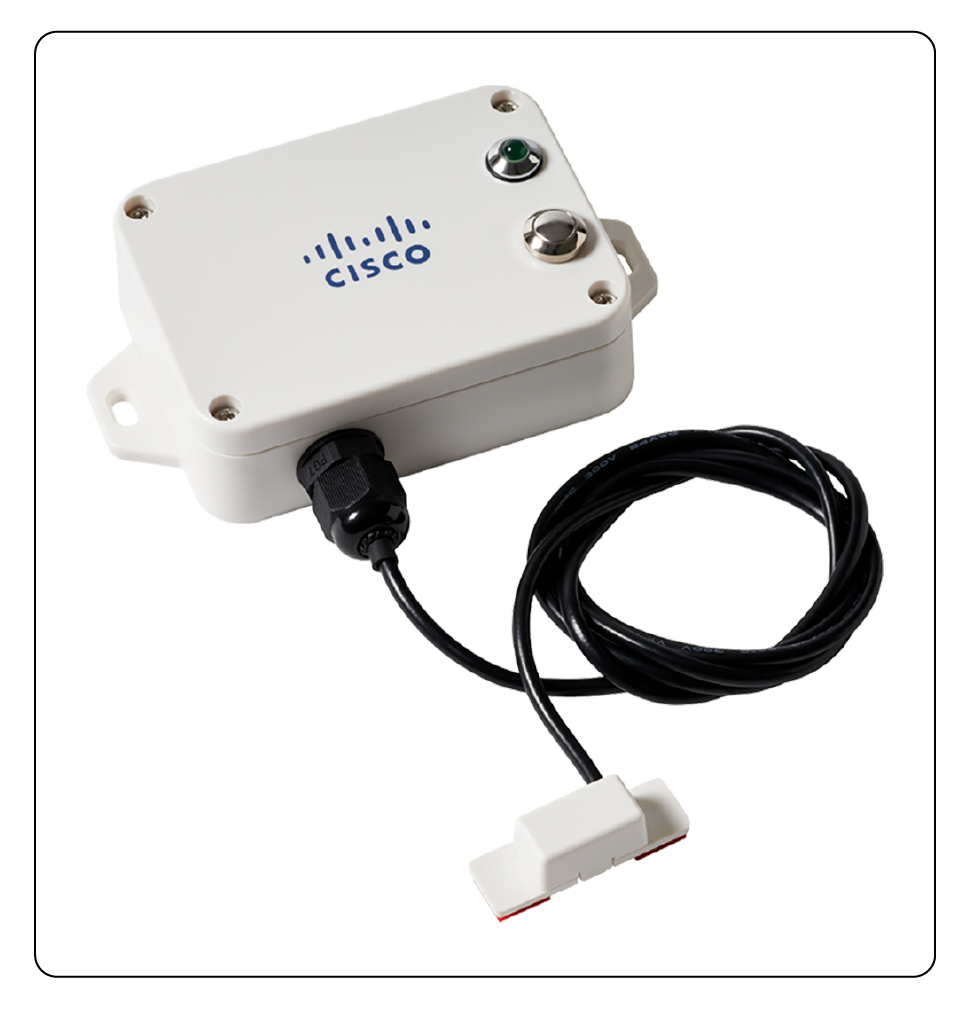
5. AV204: Door and Window Sensor
Solution overview
The AV204 is a LoRaWAN sensor that detects door and window open/close status. It is intended for use with Cisco Industrial Asset Vision.
Product image
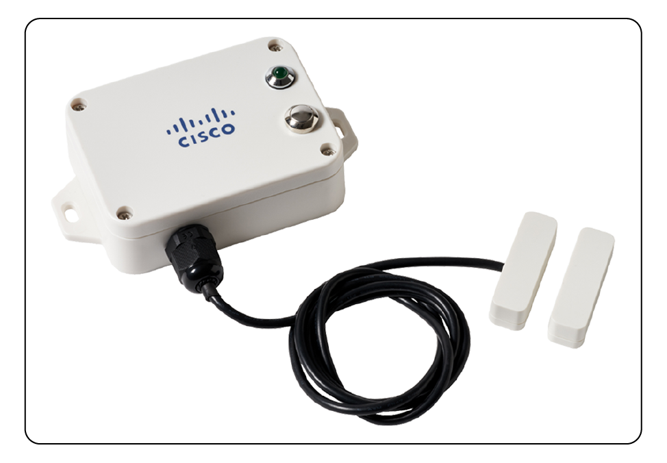
AV204 Door and Window Sensor
Key benefits
● Monitoring of doors, windows, and other items which incorporate an open/close mechanism
Product details
Table 32. Cisco part number
| Geography |
Cisco PID |
| US, Canada |
IOTAV-L-HAL-I1-US |
| Europe |
IOTAV-L-HAL-I1-EU |
| Australia, New Zealand, Brazil, Argentina, Chile |
IOTAV-L-HAL-I1-AU |
| India |
IOTAV-L-HAL-I1-IN |
Table 33. Environmental/Physical specifications
| Specification |
Description |
| Operating Temperature |
-20 to 55°C (-4 to 131 °F) |
| Storage Temperature |
-40 to 85°C (-40 to 185 °F) |
| Operating Humidity |
<90% RH (No Condensation) |
| IP Rating |
IP65 |
| Dimensions (L x W x H) |
112mm x 65mm x 32mm (4.4 x 2.55 x 1.25 inches) |
| Hall Sensor Dimensions |
42mm x 13mm x 12mm (1.65 x 0.51 x 0.47 inches) |
| Weight |
141 g (0.31 lbs) |
| Probe Lead Length |
1m |
| Sensing distance |
Less than 3cm |
Table 34. Radio
| Specification |
Description |
| Frequency Band |
800 MHz / 900 MHz ISM Band |
| Transmit power (conducted) |
US915: 20 dBm EU868: 16 dBm AU915: 20 dBm IN865: 20 dBm |
| Rx Sensitivity |
-136dBm (SF12) |
| Range |
Up to 10km (dependent on environment) |
Table 35. Measurements
| Specification |
Description |
| Battery Voltage Accuracy |
+/- 0.1V |
Table 36. Battery
| Specification |
Description |
| Battery Type |
2x 3.6V ER14505 AA in parallel |
| Operating Voltage |
3.1V to 3.65V |
| Battery Life |
5 years |
Table 37. Reporting metrics
| Monitoring |
Report on State Change? |
Default Reporting Interval |
Expected Battery Life* |
| Open/close, Battery |
Yes |
60 mins |
5 years (~100 triggers/day) |
Table 38. Product certification and compliance
| Specification |
Applicable regions |
| Safety |
|
| UL/CSA 60950-1/62368-1 |
North America |
| EN 60950-1/62368-1 |
EU |
| CB to IEC 60950-1 |
Worldwide |
| CB to IEC 62368-1 |
Worldwide |
| IEC 60529 (IP65) |
Worldwide |
| IEC 60950-22 |
Worldwide |
| EMC Immunity |
|
| EN 301489-1 |
EU |
| EN 301489-3 |
EU |
| Radio |
|
| EU 863-870 (EU) |
|
| EN 300220-1 |
EU |
| EN 300220-2 |
EU |
| CE RED |
EU |
| US 902-928 (USA, Canada) |
|
| FCC 47CFR Part 15 B and C |
USA |
| RSS210 |
Canada |
| IC ICES-003 |
Canada |
| AUS915 (LATAM, AU, NZ) |
|
| RCM approval AS/NZS4268 |
Australia, New Zealand |
| Anatel certification1 |
Brazil |
| Enacom certification |
Argentina |
| IN865 (India) |
|
| WPC certification |
India |
| Other |
|
| RoHS |
EU |
| FCC Part 2 |
USA |
| RSS 102 |
Canada |
Wireless statement
● Este equipamento não tem direito à proteção contra interferência prejudicial e não podecausar interferência em sistemas devidamente autorizados.
● This equipment is not entitled to protection against harmful interference and may not causeinterference in properly authorized systems.
EMC CISPR statement
● Este produto não é apropriado para uso em ambientes domésticos, pois poderá causarinterferências eletromagnéticas que obrigam o usuário a tomar medidas necessárias para minimizarestas interferências.
● This product is not suitable for use in a domestic environment as it may cause electromagneticinterference that requires the user to take necessary actions to minimize such interference.
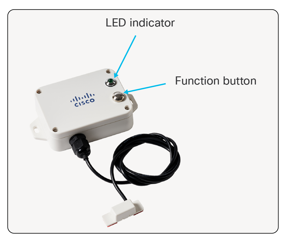
Turning AV204 On/Off
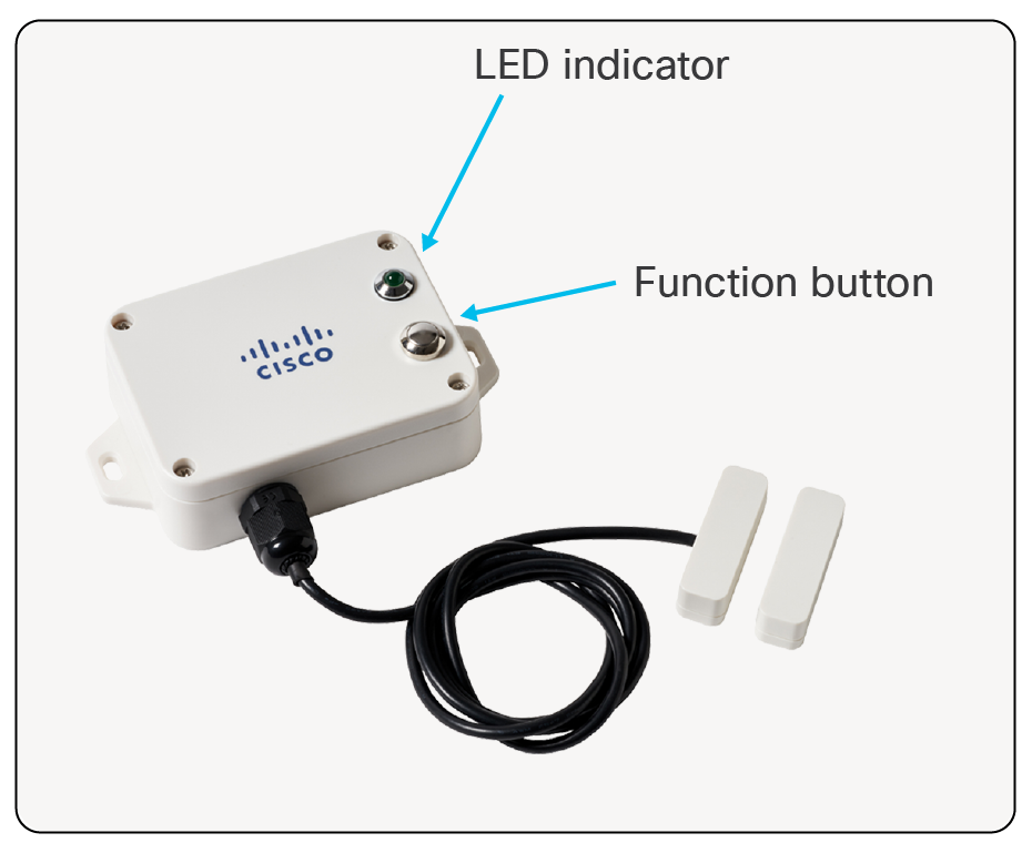
Turning AV204 On/Off
● Press and hold the Function button for 3-5 seconds until…
◦ LED blinks 20 times:
◦ Sensor has been turned off.
◦ LED illuminates solid for a few seconds:
◦ Sensor has been turned on.
◦ Sensor attempts to register with the network server.
◦ Another blink of the LED indicates that sensor has joined properly (usually happens within 30 seconds).
◦ Allow about 10 seconds after turning off before turning on.
● Once sensor has joined:
◦ Manual uplink message can be initiated with a short press of the Function button.
◦ LED will flash to indicate that message has been triggered.
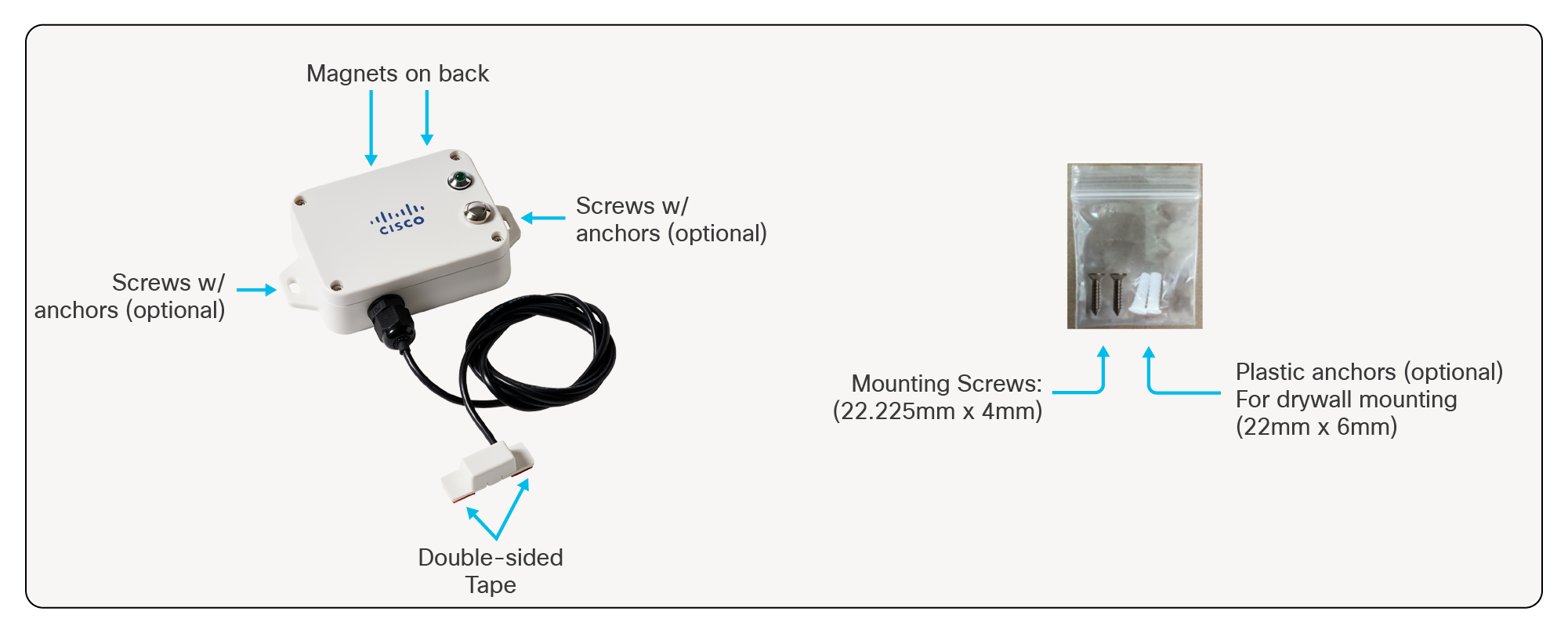
Mounting Accessories and Methods AV204
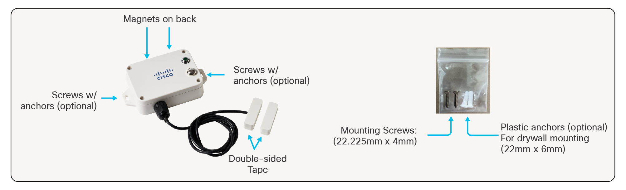
Mounting Accessories and Methods AV204
● Magnetic mount to ferromagnetic surfaces.
● Screws for attaching to walls and other flat surfaces.
◦ Package also includes plastic anchors for installation into material such as drywall/sheetrock.
● Double-sided tape for base unit (not included).
● Double-sided tape on the external probes.
◦ Be sure to clean/dry the mounting surface prior to mounting.
Solution overview
The AV205 is a LoRaWAN sensor which can be used to detect water leaks. It is intended for use with Cisco Industrial Asset Vision.
Product image
AV205 Water Leak Sensor
Product details
Table 39. Cisco part number
| Geography |
Cisco PID |
| US, Canada |
IOTAV-L-WLK-O1-US |
| Europe |
IOTAV-L-WLK-O1-EU |
| Australia, New Zealand, Brazil, Argentina, Chile |
IOTAV-L-WLK-O1-AU |
| India |
IOTAV-L-WLK-O1-IN |
Table 40. Environmental/Physical specifications
| Specification |
Description |
| Operating Temperature |
-20 to 55°C (-4 to 131 °F) |
| Storage Temperature |
-40 to 85°C (-40 to 185 °F) |
| Operating Humidity |
<90% RH (No Condensation) |
| IP Rating |
IP67 |
| Dimensions (L x W x H) |
112mm x 65mm x 32mm (4.4 x 2.55 x 1.25 inches) |
| Water Sensor Dimensions |
38.5mm x 11.9mm x 13.7mm (1.51 x 0.46 x 0.53 inches) |
| Weight |
141 g (0.31 lbs) |
| Probe Lead Length |
1m |
| Probe Temperature |
Up to 50 °C |
Table 41. Radio
| Specification |
Description |
| Frequency Band |
800 MHz / 900 MHz ISM Band |
| Transmit power (conducted) |
US915: 20 dBm EU868: 16 dBm AU915: 20 dBm IN865: 20 dBm |
| Rx Sensitivity |
-136dBm (SF12) |
| Range |
Up to 10km (dependent on environment) |
Table 42. Measurements
| Specification |
Description |
| Battery Voltage Accuracy |
+/- 0.1V |
Table 43. Battery
| Specification |
Description |
| Battery Type |
2x 3.6V ER14505 AA in parallel |
| Operating Voltage |
3.1V to 3.65V |
| Battery Life |
5 years (25C, 15-minute reports, TxPower=20dBm, SF10) |
Table 44. Reporting metrics
| Monitoring |
Report on State Change? |
Default Reporting Interval |
Expected Battery Life* |
| Leak, Battery |
Yes |
60 mins |
5 years |
Table 45. Product certification and compliance
| Specification |
Applicable regions |
| Safety |
|
| UL/CSA 60950-1/62368-1 |
North America |
| EN 60950-1/62368-1 |
EU |
| CB to IEC 60950-1 |
Worldwide |
| CB to IEC 62368-1 |
Worldwide |
| IEC 60529 (IP67) |
Worldwide |
| IEC 60950-22 |
Worldwide |
| EMC immunity |
|
| EN 301489-1 |
EU |
| EN 301489-3 |
EU |
| Radio |
|
| EU 863-870 (EU) |
|
| EN 300220-1 |
EU |
| EN 300220-2 |
EU |
| CE RED |
EU |
| US 902-928 (USA, Canada) |
|
| FCC 47CFR Part 15 B and C |
USA |
| RSS210 |
Canada |
| IC ICES-003 |
Canada |
| AUS915 (LATAM, AU, NZ) |
|
| RCM approval AS/NZS4268 |
Australia, New Zealand |
| Anatel certification1 |
Brazil |
| Enacom certification |
Argentina |
| IN865 (India) |
|
| WPC certification |
India |
| Other |
|
| RoHS |
EU |
| FCC Part 2 |
USA |
| RSS 102 |
Canada |
Wireless statement
● Este equipamento não tem direito à proteção contra interferência prejudicial e não podecausar interferência em sistemas devidamente autorizados.
● This equipment is not entitled to protection against harmful interference and may not causeinterference in properly authorized systems.
EMC CISPR statement
● Este produto não é apropriado para uso em ambientes domésticos, pois poderá causarinterferências eletromagnéticas que obrigam o usuário a tomar medidas necessárias para minimizarestas interferências.
● This product is not suitable for use in a domestic environment as it may cause electromagneticinterference that requires the user to take necessary actions to minimize such interference.
Turning AV205 On/Off
Turning AV205 On/Off
● Press and hold the Function button for 3-5 seconds until…
◦ LED blinks 20 times:
◦ Sensor has been turned off.
◦ LED illuminates solid for a few seconds:
◦ Sensor has been turned on.
◦ Sensor attempts to register with the network server.
◦ Another blink of the LED indicates that sensor has joined properly (usually happens within 30 seconds).
◦ Allow about 10 seconds after turning off before turning on.
● Once sensor has joined:
◦ Manual uplink message can be initiated with a short press of the Function button.
◦ LED will flash to indicate that message has been triggered.
Mounting Accessories and Methods AV205
Mounting Accessories and Methods AV205
● Magnetic mount to ferromagnetic surfaces
● Screws for attaching to walls and other flat surfaces
◦ Package also includes plastic anchors for installation into material such as drywall/sheetrock.
● Double-sided tape for base unit (not included)
● Double-sided tape on the external probe
◦ Be sure to clean/dry the mounting surface prior to mounting.
Solution overview
The AV206 is a LoRaWAN sensor which detects ambient light intensity. It is intended for use with Cisco Industrial Asset Vision.
Product image
AV206 Light Level Sensor
Product details
Table 46. Cisco part number
| Geography |
Cisco PID |
| US, Canada |
IOTAV-L-LUX-I1-US |
| Europe |
IOTAV-L-LUX-I1-EU |
| Australia, New Zealand, Brazil, Argentina, Chile |
IOTAV-L-LUX-I1-AU |
| India |
IOTAV-L-LUX-I1-IN |
Table 47. Environmental/Physical specifications
| Specification |
Description |
| Operating Temperature |
-20 to 55°C (-4 to 131 °F) |
| Storage Temperature |
-40 to 85°C (-40 to 185 °F) |
| Operating Humidity |
<90% RH (No Condensation) |
| IP Rating |
IP65 |
| Dimensions (L x W x H) |
112mm x 65mm x 32mm (4.4 x 2.55 x 1.25 inches) |
| Weight |
141 g (0.31 lbs) |
Table 48. Radio
| Specification |
Description |
| Frequency Band |
800 MHz / 900 MHz ISM Band |
| Transmit power (conducted) |
US915: 20 dBm EU868: 16 dBm AU915: 20 dBm IN865: 20 dBm |
| Rx Sensitivity |
-136dBm (SF12) |
| Range |
Up to 10km (dependent on environment) |
Table 49. Measurements
| Specification |
Description |
| Illuminance Measurement Range |
0.01 Lux to 157K Lux |
| Illuminance Accuracy |
+/- 10%; Test Condition: white LED light, 6500K, room temperature |
| Battery Voltage Accuracy |
+/- 0.1V |
Table 50. Battery
| Specification |
Description |
| Battery Type |
2x 3.6V ER14505 AA in parallel |
| Operating Voltage |
3.1V to 3.65V |
| Battery Life |
5 years (25C, 15-minute reports, TxPower=20dBm, SF10) |
Table 51. Reporting metrics
| Monitoring |
Default Reporting Interval |
Expected Battery Life* |
| Illuminance, Battery |
15 mins |
5 years |
Table 52. Product certification and compliance
| Specification |
Applicable regions |
| Safety |
|
| UL/CSA 60950-1/62368-1 |
North America |
| EN 60950-1/62368-1 |
EU |
| CB to IEC 60950-1 |
Worldwide |
| CB to IEC 62368-1 |
Worldwide |
| IEC 60529 (IP65) |
Worldwide |
| IEC 60950-22 |
Worldwide |
| EMC immunity |
|
| EN 301489-1 |
EU |
| EN 301489-3 |
EU |
| Radio |
|
| EU 863-870 (EU) |
|
| EN 300220-1 |
EU |
| EN 300220-2 |
EU |
| CE RED |
EU |
| US 902-928 (USA, Canada) |
|
| FCC 47CFR Part 15 B and C |
USA |
| RSS210 |
Canada |
| IC ICES-003 |
Canada |
| AUS915 (LATAM, AU, NZ) |
|
| RCM approval AS/NZS4268 |
Australia, New Zealand |
| Anatel certification1 |
Brazil |
| Enacom certification |
Argentina |
| IN865 (India) |
|
| WPC certification |
India |
| Other |
|
| RoHS |
EU |
| FCC Part 2 |
USA |
| RSS 102 |
Canada |
Wireless statement
● Este equipamento não tem direito à proteção contra interferência prejudicial e não podecausar interferência em sistemas devidamente autorizados.
● This equipment is not entitled to protection against harmful interference and may not causeinterference in properly authorized systems.
EMC CISPR statement
● Este produto não é apropriado para uso em ambientes domésticos, pois poderá causarinterferências eletromagnéticas que obrigam o usuário a tomar medidas necessárias para minimizarestas interferências.
● This product is not suitable for use in a domestic environment as it may cause electromagneticinterference that requires the user to take necessary actions to minimize such interference.
Turning AV206 On/Off
Turning AV206 On/Off
● Press and hold the Function button for 3-5 seconds until…
◦ LED blinks 20 times:
◦ Sensor has been turned off.
◦ LED illuminates solid for a few seconds:
◦ Sensor has been turned on.
◦ Sensor attempts to register with the network server.
◦ Another blink of the LED indicates that sensor has joined properly (usually happens within 30 seconds).
◦ Allow about 10 seconds after turning off before turning on.
● Once sensor has joined:
◦ Manual uplink message can be initiated with a short press of the Function button.
◦ LED will flash to indicate that message has been triggered.
Mounting Accessories and Methods AV206
Mounting Accessories and Methods AV206
● Magnetic mount to ferromagnetic surfaces
● Screws for attaching to walls and other flat surfaces
◦ Package also includes plastic anchors for installation into material such as drywall/sheetrock.
● Double-sided tape (not included)
8. AV207: Indoor Occupancy Sensor
Solution overview
The AV207 is a LoRaWAN indoor occupancy sensor. The AV207 senses the movement of people, animals, or other objects, and if a person or an object moves in the monitoring area, the sensor detects the infrared signal and reports the status information. The AV207 is intended for use with Cisco Industrial Asset Vision.
Product image
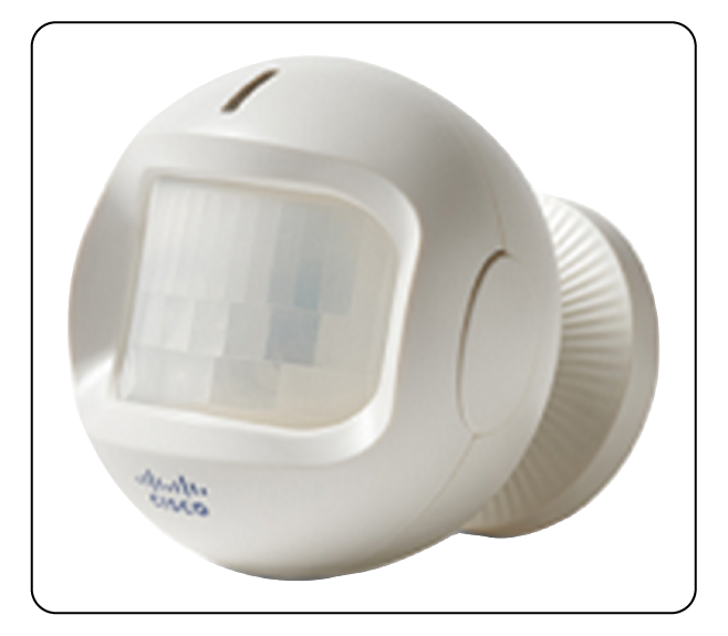
AV207 Indoor Occupancy Sensor
Key benefits
● Area Access Monitoring
● Detect Ingress/Egress of people, animals, or objects
Product details
Table 53. Cisco part number
| Geography |
Cisco PID |
| US, Canada |
IOTAV-L-OCU-I1-US |
| Europe |
IOTAV-L-OCU-I1-EU |
| Australia, New Zealand, Brazil, Argentina, Chile |
IOTAV-L-OCU-I1-AU |
| India |
IOTAV-L-OCU-I1-IN |
Table 54. Environmental/Physical specifications
| Specification |
Description |
| Operating Temperature |
-20 to 55°C (-4 to 131 °F) |
| Storage Temperature |
-40 to 85°C (-40 to 185 °F) |
| Operating Humidity |
<90% RH (No Condensation) |
| IP Rating |
IP30 |
| Dimensions (L x W x H) |
78mm x 78.8mm x 82.2mm (3.07 x 3.10 x 3.23 inches) |
| Weight |
128.8 g (0.28 lbs) |
Table 55. Radio
| Specification |
Description |
| Frequency Band |
800 MHz / 900 MHz ISM Band |
| Transmit power (conducted) |
US915: 20 dBm EU868: 16 dBm AU915: 20 dBm IN865: 20 dBm |
| Rx Sensitivity |
-136dBm (SF12) |
| Range |
Up to 10km (dependent on environment) |
Table 56. Measurements
| Specification |
Description |
| Sensing distance |
2 meters to 12 meters |
| Mounting Height |
2 to 2.2 meters above ground level |
| Mounting Angle |
Tilt 15° downward |
| Sensing Angle |
Horizontal 110°, Vertical 60° |
| Temperature Measurement Range |
-20 to 55°C (-4 to 131 °F) |
| Moving speed to trigger |
>= 0.2 m/s |
| Temperature Accuracy |
+/- 2°C@ 25 °C |
| Illuminance Measurement Range |
3 Lux to 1100 Lux |
| Illuminance Accuracy |
+/- 15% |
| Battery Voltage Accuracy |
+/- 0.1V |
Table 57. Battery
| Specification |
Description |
| Battery Type |
2x 3.6V ER14505 AA in parallel |
| Operating Voltage |
3.1V to 3.65V |
| Battery Life |
2.5 years (25C, 100 triggers/day, TxPower=20dBm, SF10) |
Table 58. Reporting metrics
| Monitoring |
Report on State Change? |
Default Reporting Interval |
Expected Battery Life* |
| Motion, Temperature, Illuminance, Battery |
Yes |
60 mins |
2.5 years (~100 triggers/day) |
Table 59. Product certification and compliance
| Specification |
Applicable regions |
| Safety |
|
| UL/CSA 60950-1/62368-1 |
North America |
| EN 60950-1/62368-1 |
EU |
| CB to IEC 60950-1 |
Worldwide |
| CB to IEC 62368-1 |
Worldwide |
| IEC 60529 (IP30) |
Worldwide |
| IEC 60950-22 |
Worldwide |
| EMC immunity |
|
| EN 301489-1 |
EU |
| EN 301489-3 |
EU |
| Radio |
|
| EU 863-870 (EU) |
|
| EN 300220-1 |
EU |
| EN 300220-2 |
EU |
| CE RED |
EU |
| US 902-928 (USA, Canada) |
|
| FCC 47CFR Part 15 B and C |
USA |
| RSS210 |
Canada |
| IC ICES-003 |
Canada |
| AUS915 (LATAM, AU, NZ) |
|
| RCM approval AS/NZS4268 |
Australia, New Zealand |
| Anatel certification1 |
Brazil |
| Enacom certification |
Argentina |
| IN865 (India) |
|
| WPC certification |
India |
| Other |
|
| RoHS |
EU |
| FCC Part 2 |
USA |
| RSS 102 |
Canada |
Wireless statement
● Este equipamento não tem direito à proteção contra interferência prejudicial e não podecausar interferência em sistemas devidamente autorizados.
● This equipment is not entitled to protection against harmful interference and may not causeinterference in properly authorized systems.
EMC CISPR statement
● Este produto não é apropriado para uso em ambientes domésticos, pois poderá causarinterferências eletromagnéticas que obrigam o usuário a tomar medidas necessárias para minimizarestas interferências.
● This product is not suitable for use in a domestic environment as it may cause electromagneticinterference that requires the user to take necessary actions to minimize such interference.
Turning AV207 On/Off
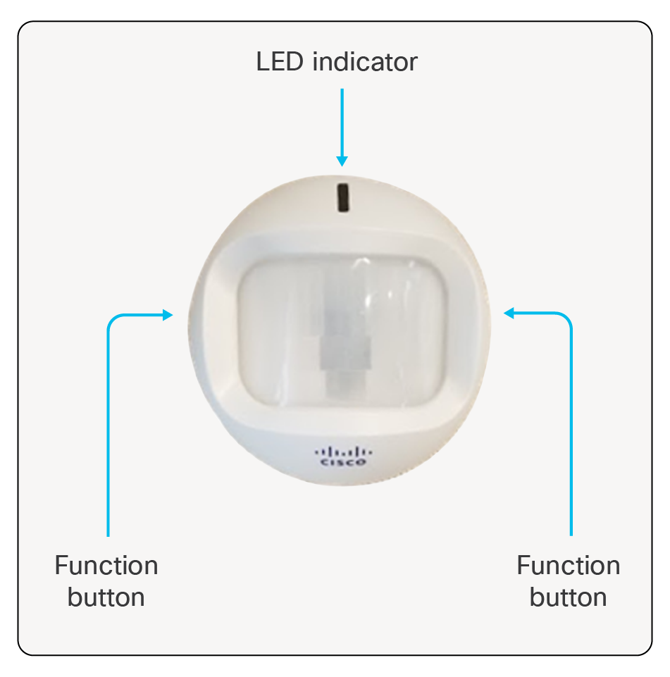
Turning AV207 On/Off
● Turn on: Press and hold either function button until indicator flashes green and red.
◦ Sensor attempts to register with the network server.
◦ Another blink of the LED indicates that sensor has joined properly (usually happens within 30 seconds).
● Turn off: Press and hold both function buttons until indicator flashes green 20 times.
● Allow about 10 seconds after turning off before turning on.
● Once sensor has joined:
◦ Manual uplink message can be initiated with a short press of either function button.
◦ LED will flash green to indicate that message has been triggered.
Mounting Accessories and Methods AV207
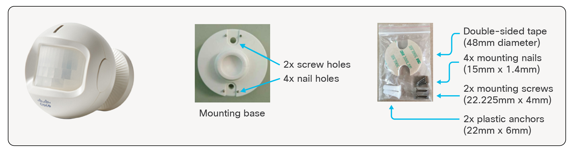
Mounting Accessories and Methods AV207
● Screws for attaching to walls and other flat surfaces
◦ Package also includes plastic anchors for installation into material such as drywall/sheetrock
● Nails for attaching to walls and other flat surfaces
● Double-sided tape
◦ Be sure to clean/dry the surface before application
AV207 Motion Detection Range
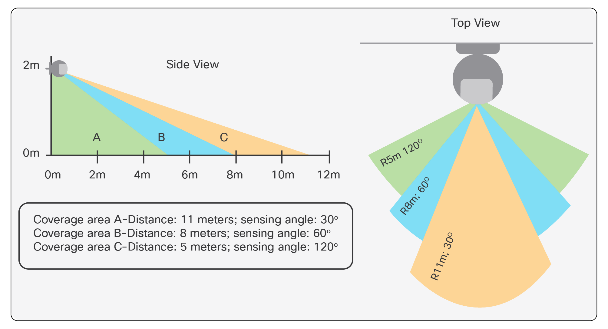
AV207 Motion Detection Range
AV207 Disable/Detection Time
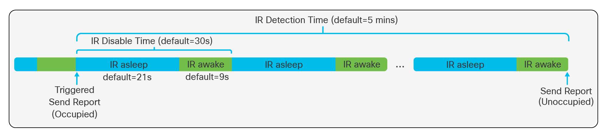
AV207 Disable/Detection Time
● To conserve battery, IR detection is not running constantly.
● IR detection is done within a window called IR Disable Time.
● IR sensor is asleep during first 70% of IR Disable Time window. Sensor is awake for the last 30%.
● Once sensor is triggered, sensor continues to evaluate for occupancy according to IR Disable Time window.
● If motion is detected during the awake window, sensor proceeds to the next IR asleep window and IR Detection Time counter is reset.
● Once motion has been undetected for the IR Detection Time window, a data report indicating “not occupied” is sent.
9. AV250: Machine Temperature Sensor
Solution overview
The AV250 is a LoRaWAN sensor which can be used to detect temperature of an environment or to a medium to which its thermocouple is connected. It is intended for use with Cisco Industrial Asset Vision.
Product image
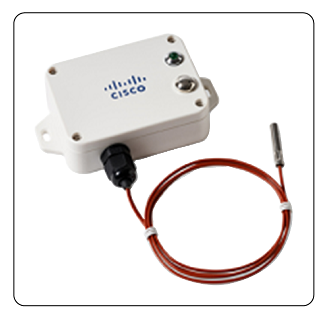
AV250 Machine Temperature Sensor
Key benefits
● Temperature measuring Equipment
● Measuring temperature in manufacturing ovens and industrial control equipment
Product details
Table 60. Cisco part number
| Geography |
Cisco PID |
| US, Canada |
IOTAV-L-MTM-O1-US |
| Europe |
IOTAV-L-MTM-O1-EU |
| Australia, New Zealand, Brazil, Argentina, Chile |
IOTAV-L-MTM-O1-AU |
| India |
IOTAV-L-MTM-O1-IN |
Table 61. Environmental/Physical specifications
| Specification |
Description |
| Operating Temperature |
-20 to 55°C (-4 to 131 °F) |
| Storage Temperature |
-40 to 85°C (-40 to 185 °F) |
| Operating Humidity |
<90% RH (No Condensation) |
| IP Rating |
IP67 |
| Base Unit Dimensions (L x W x H) |
112mm x 88.19mm x 32mm (4.4 x 3.47 x 1.25 inches) |
| Weight |
141 g (0.31 lbs) |
| Probe Type |
Type T thermocouple |
| Probe Dimensions |
5mm (diameter); 30mm long (rounded) |
| Probe Lead Length |
1m |
Table 62. Radio
| Specification |
Description |
| Frequency Band |
800 MHz / 900 MHz ISM Band |
| Transmit power (conducted) |
US915: 20 dBm EU868: 16 dBm AU915: 20 dBm IN865: 20 dBm |
| Rx Sensitivity |
-136dBm (SF12) |
| Range |
Up to 10km (dependent on environment) |
Table 63. Measurements
| Specification |
Description |
| External PT1000 probe temperature range |
-40 to 125°C (-4 to 257 °F) |
| Temperature Accuracy |
(Assume base unit is @ 0°C ≤ t ≤ 55°C) Probe @ 0C ≤ t ≤ 55°C: +/- 0.5°C Probe @ -40°C ≤ t < 0°C: +/- 3°C Probe @ 55°C < t ≤ 125°C: +/- 1.5°C |
| Battery Voltage Accuracy |
+/- 0.1V |
Table 64. Battery
| Specification |
Description |
| Battery Type |
2x 3.6V ER14505 AA in parallel |
| Operating Voltage |
3.1V to 3.65V |
| Battery Life |
4.8 years |
Table 65. Reporting metrics
| Monitoring |
Default Reporting Interval |
Expected Battery Life* |
| Temperature, Battery |
15 mins |
4.8 years |
Table 66. Product certification and compliance
| Specification |
Applicable regions |
| Safety |
|
| UL/CSA 60950-1/62368-1 |
North America |
| EN 60950-1/62368-1 |
EU |
| CB to IEC 60950-1 |
Worldwide |
| CB to IEC 62368-1 |
Worldwide |
| IEC 60529 (IP67) |
Worldwide |
| IEC 60950-22 |
Worldwide |
| EMC immunity |
|
| EN 301489-1 |
EU |
| EN 301489-3 |
EU |
| Radio |
|
| EU 863-870 (EU) |
|
| EN 300220-1 |
EU |
| EN 300220-2 |
EU |
| CE RED |
EU |
| US 902-928 (USA, Canada) |
|
| FCC 47CFR Part 15 B and C |
USA |
| RSS210 |
Canada |
| IC ICES-003 |
Canada |
| AUS915 (LATAM, AU, NZ) |
|
| RCM approval AS/NZS4268 |
Australia, New Zealand |
| Anatel certification1 |
Brazil |
| Enacom certification |
Argentina |
| IN865 (India) |
|
| WPC certification |
India |
| Other |
|
| RoHS |
EU |
| FCC Part 2 |
USA |
| RSS 102 |
Canada |
Wireless statement
● Este equipamento não tem direito à proteção contra interferência prejudicial e não podecausar interferência em sistemas devidamente autorizados.
● This equipment is not entitled to protection against harmful interference and may not causeinterference in properly authorized systems.
EMC CISPR statement
● Este produto não é apropriado para uso em ambientes domésticos, pois poderá causarinterferências eletromagnéticas que obrigam o usuário a tomar medidas necessárias para minimizarestas interferências.
● This product is not suitable for use in a domestic environment as it may cause electromagneticinterference that requires the user to take necessary actions to minimize such interference.
Turning AV250 On/Off
Turning AV250 On/Off
● Press and hold the Function button for 3-5 seconds until….
◦ LED blinks 20 times:
◦ Sensor has been turned off.
◦ LED illuminates solid for a few seconds:
◦ Sensor has been turned on.
◦ Sensor attempts to register with the network server.
◦ Another blink of the LED indicates that sensor has joined properly (usually happens within 30 seconds).
◦ Allow about 10 seconds after turning off before turning on.
● Once sensor has joined:
◦ Manual uplink message can be initiated with a short press of the Function button.
◦ LED will flash to indicate that message has been triggered.
Mounting Accessories and Methods AV250
Mounting Accessories and Methods AV250
● Magnetic mount to ferromagnetic surfaces
● Screws for attaching to walls and other flat surfaces
◦ Package also includes plastic anchors for installation into material such as drywall/sheetrock.
● Double-sided tape (not included)
10. AV251: Vibration Monitoring Sensor
Solution Overview
The AV251 is a LoRaWAN vibration sensor capable of reporting Velocity RMS, Acceleration RMS, Peak, Displacement, Kurtosis, Crest factor, Skewness, and Standard Deviation values. The AV251 is intended for use with Cisco Industrial Asset Vision and is ideal for applications such as pumps, HVAC systems, motors, facility monitoring, and more.
Product Image
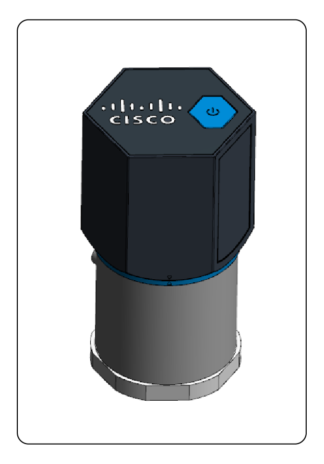
AV251 LoRaWAN Wireless Vibration Sensor
Key Benefits
● LoRaWAN wireless connectivity
● Built-in 3-axis accelerometer and temperature sensor
● On-board computing to provide Velocity RMS, Acceleration RMS, Acceleration Peak, Displacement, Kurtosis, Crest factor, Skewness, and Standard Deviation.
● Battery-powered, no wiring needed
● ISO 10816-3 compliant
● Supports wide temperature range of -20 to +70 °C
● IP66 enclosure design
Product Details
Table 67. Sensor Cisco Part Numbers
| Geography |
Cisco PID |
| US, Canada |
AV251-VIB-US |
| Europe |
AV251-VIB-EU |
| Australia, New Zealand, Brazil, Argentina, Chile |
AV251-VIB-AU |
Table 68. Mounting Options Cisco Part Numbers
| Item |
Cisco PID |
| Magnetic base |
AV251-MGTB= |
| Non-magnetic, Metal base |
AV251-MB= (epoxy/adhesive not included) |
Table 69. Environmental/Physical Specifications
| Specification |
Description |
| Operating Temperature |
-20 to +70 °C (-4 to +158 °F) |
| Storage Temperature |
-25 to +90 °C (-13 to +194 °F) |
| Operating Humidity |
10% to 95% RH |
| Storage Humidity |
10% to 95% RH |
| IP Rating |
IP66 |
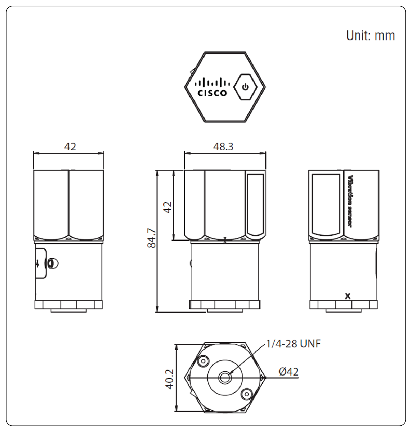
| Dimensions (H x D) |
84.7 x 48.3 mm (3.3 x 1.9 inches) |
| Weight |
AV251-VIB-xx w/o batteries: 136.4g (4.81 ounces) Stud mount: 1.68g (0.059 ounces) AV251-MGTB=: 43g (1.52 ounces) AV251-MB=: 35g (1.23 ounces) |
| Mounting |
Stud mount (included with base sensor PID) Magnetic base (AV251-MGTB=) Metal base (AV251-MB=) w/ epoxy (not included) |
Table 70. Radio Specifications
| Specification |
Description |
| Frequency Band |
AV251-VIB-US: 902-928MHz ISM Band AV251-VIB-EU: 863-870MHz ISM Band AV251-VIB-AU: 915-928MHz ISM Band |
| Tx Power (conducted) |
AV251-VIB-US: 17.5dBm AV251-VIB-EU: 13.4dBm AV251-VIB-AU: 17.5dBm |
| Antenna gain (internal) |
-0.7dBi |
| Rx Sensitivity |
-148dBm |
| Range |
Up to 10km (6.213 miles) (dependent on environment) |
Table 71. Measurement Specifications
| Specification |
Description |
| Measurement Axis |
X, Y, Z |
| Frequency Range |
10 – 1000Hz |
| Amplitude Range |
+/- 16g |
| Output Data Rate |
6600Hz |
| Resolution |
16 bit |
| Accuracy (Fc = 100Hz) |
Under 5% |
| Noise (Ta = 25C, 0g) |
+/- 40mg |
| Nonlinearity |
+/- 0.5% |
| Cross-Axis Sensitivity |
+/- 1% |
| Sensitivity change due to temperature |
+/- 0.02 %/degC |
| Base Temperature Measurement Range |
-20 to +120C |
| Accuracy (Ta = 27C. direct contact w/ heat source via metal base) |
-5C @ +85C base temperature -10C @ +120C base temperature |
Table 72. Battery Specifications
| Specification |
Description |
| Battery Type |
3.6V ER14505 AA, Qty=2 (in parallel) Supplied with sensor |
| Battery Life |
2 years (update interval = 1 per hour) |
Table 73. Reporting Metrics
| Monitoring |
Default Reporting Interval |
Expected Battery Life* |
|
| Per axis (X, Y, and Z) |
Velocity RMS |
60 mins |
2 years |
| Acceleration RMS |
|||
| Acceleration Peak |
|||
| Displacement |
|||
| Kurtosis |
|||
| Skewness |
|||
| Standard Deviation |
|||
| Crest Factor |
|||
| Temperature |
|||
| Battery |
|||
Table 74. Product Certification and Compliance
| Specification |
Applicable regions |
| Safety |
|
| UL 61010-1/CSA 22.2 No. 61010-1 |
North America |
| EN/IEC 62368-1 Ed 3 |
Worldwide |
| IEC 60529 (IP66) |
Worldwide |
| EMC Immunity |
|
| EN 301489-1/-3 |
EU |
| Radio |
|
| EU 863-870 (EU) |
|
| EN 300220-1/-2 |
EU |
| CE |
EU |
| US 902-928 (USA, Canada) |
|
| FCC 47 CFR Part 15 Subpart B |
USA |
| FCC 47 CFR Part 15 Subpart C |
USA |
| FCC 47 CFR 15.247 |
USA |
| RSS247 |
Canada |
| ICES-003 |
Canada |
| AU 915-928 (LATAM, AU, NZ) |
|
| RCM approval AS/NZS4268 |
Australia, New Zealand |
| Anatel certification1 |
Brazil |
| Enacom certification |
Argentina |
| Other |
|
| EN62311, RoHS |
EU |
| FCC 47 CFR Part 2 |
USA |
| RSS 102 |
Canada |
Wireless statement
● Este equipamento não tem direito à proteção contra interferência prejudicial e não pode causar interferência em sistemas devidamente autorizados.
● This equipment is not entitled to protection against harmful interference and may not cause interference in properly authorized systems.
EMC CISPR statement
● Este produto não é apropriado para uso em ambientes domésticos, pois poderá causar interferências eletromagnéticas que obrigam o usuário a tomar medidas necessárias para minimizar estas interferências.
● This product is not suitable for use in a domestic environment as it may cause electromagnetic interference that requires the user to take necessary actions to minimize such interference.
Dimensions
Turning AV251 On/Off
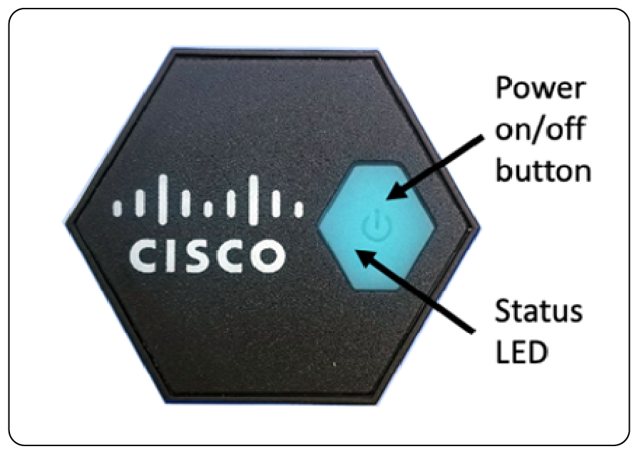
To turn the sensor on, press firmly in the center of the power button and release. If the LED blinks for 10 seconds, this means it has entered a waiting state and will not attempt to join the network for 5 minutes. This waiting state can be avoided by turning off (press/release the power button) the sensor for 20 seconds and then turning the sensor back on.
Otherwise, the LED should illuminate for 3 seconds. During this time, the sensor will attempt to register with the Industrial Asset Vision cloud service. When this has succeeded, the LED will again illuminate for 3 seconds. If the sensor is unable to register, the LED will quickly blink for about 10 seconds (this will only happen if multiple attempts over the course of several minutes are unsuccessful). In this case, the sensor should be turned off, the connectivity issue should be resolved, and then the sensor should be turned on, again.
Assuming the batteries are installed and are at a suitable level, if the LED never illuminates or blinks, it means the sensor was already on and now has been turned off.
Mounting Accessories and Methods AV251
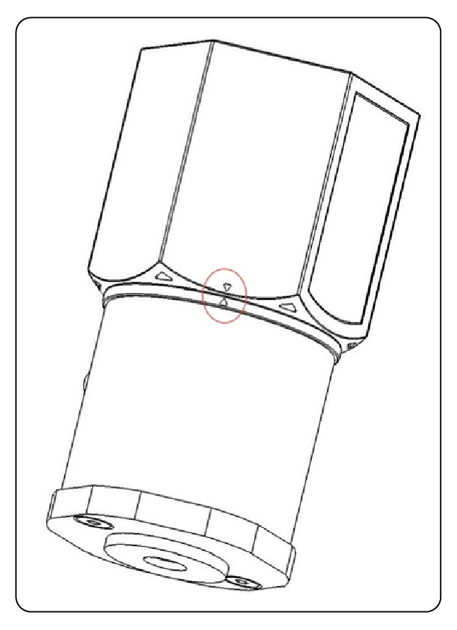
Tighten Chassis
Turn the top chassis clockwise to the locking point to create a tight connection with the bottom chassis.
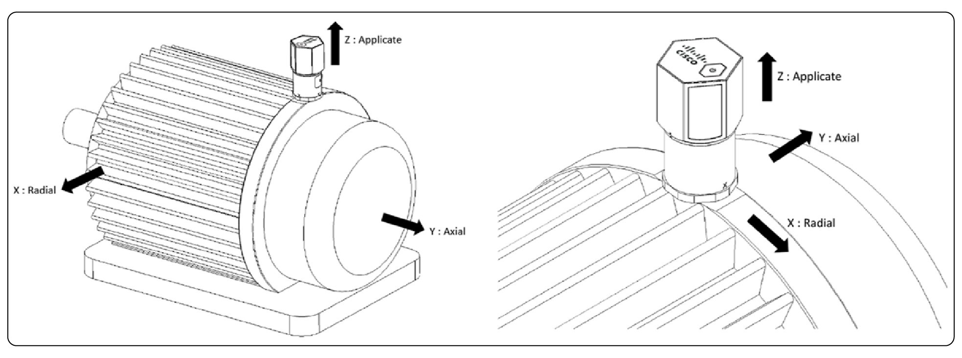
Installation Direction
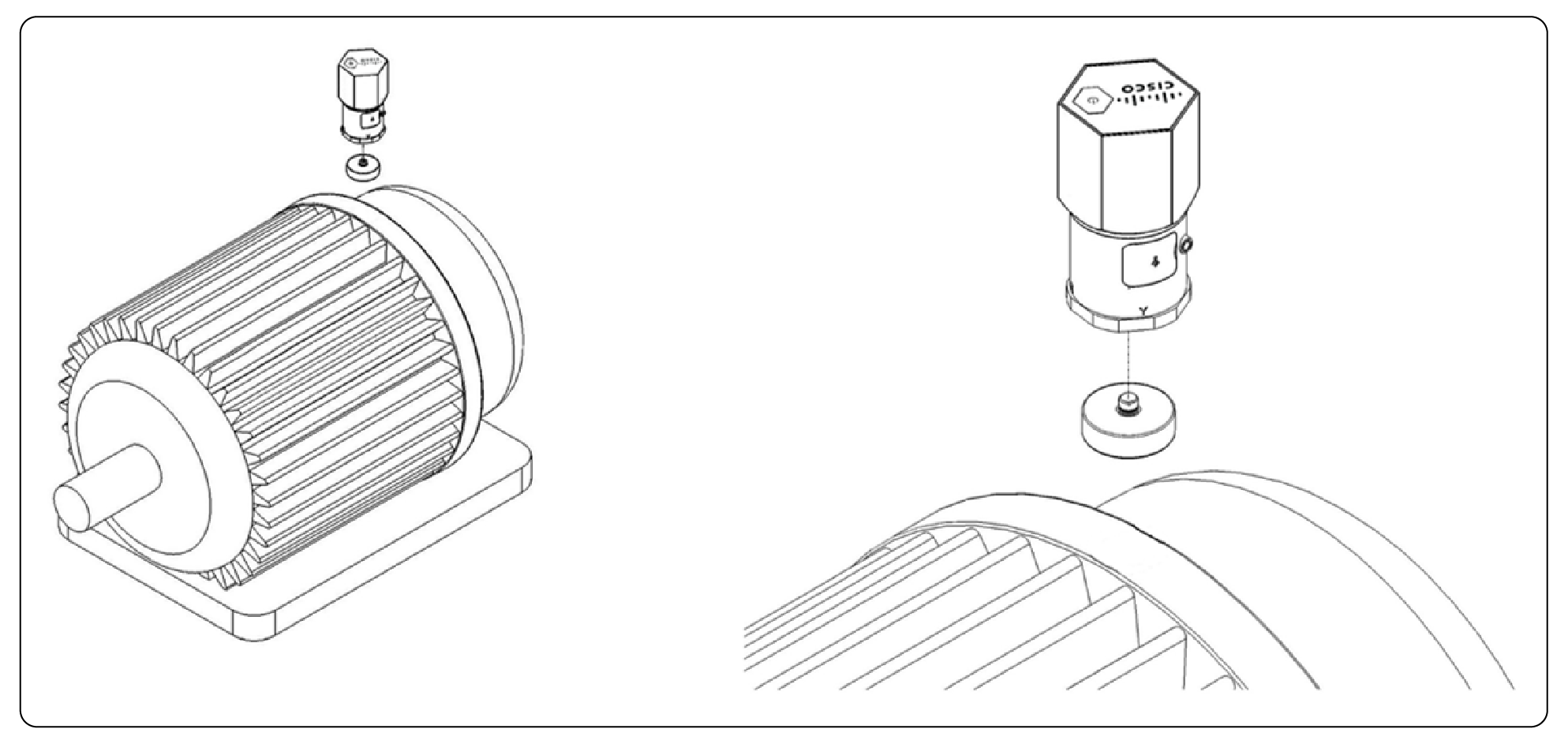
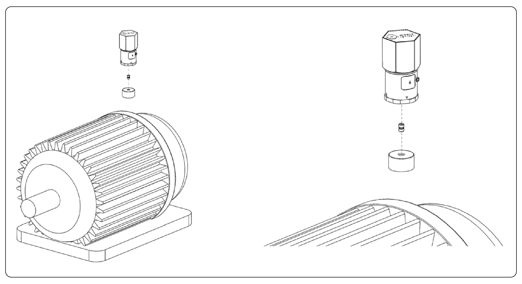
The AV251 reports vibration on the x, y, and z axis. Mount the sensor with the orientation shown below to ensure proper reporting of eigenvalues.
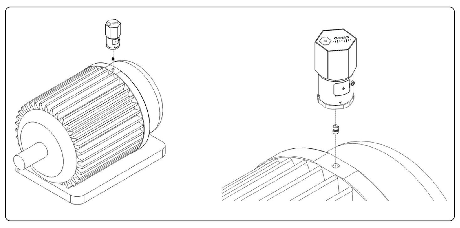
Stud Mount
1. Drill a hole in the motor surface (1/4”-28).
2. Fasten the sensor and the stud.
3. Fasten the sensor (with stud attached) to the corresponding hole in the motor surface. When using a wrench to fasten the sensor, make sure to place the head of the wrench around the base of the sensor. Do not place the head of the wrench around the shaft part of the sensor.
Magnetic Base Mount
1. Fasten the magnetic base on the motor.
2. Fasten the sensor and the magnetic base.
Metal Base Mount
1. Fasten sensor to metal base using mounting stud.
2. Use epoxy glue adhesive (24-hour drying variety) to attach the metal base to the motor.
Replacing batteries
1. Slowly remove the top chassis.
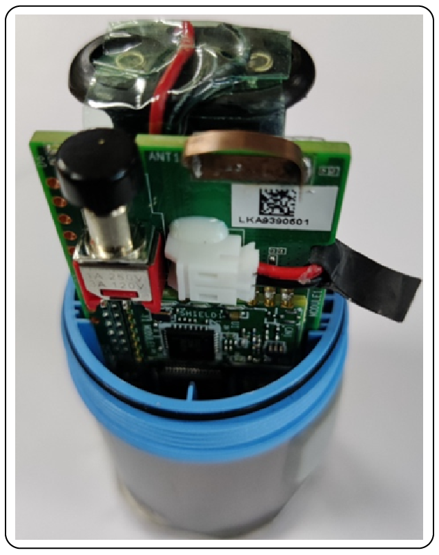
2. Grab the mylar and disconnect the battery holder connector from the connector on the PCB.
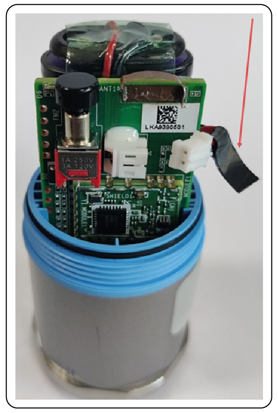
3. Take out the battery holder and plug-in new batteries. Make sure both the batteries are in the right anode and cathode positions.
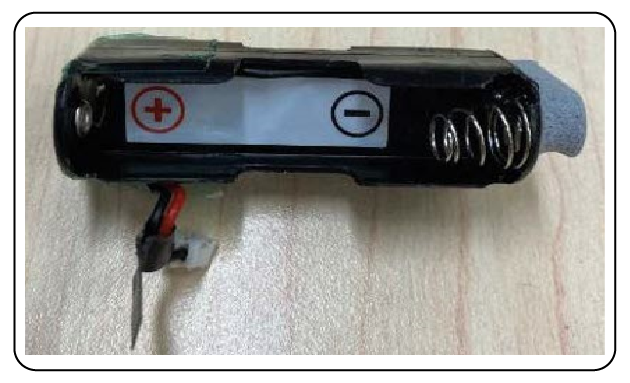
4. Re-insert the battery pack into the sensor enclosure, wrap the wire through the notch in the PCB, and connect the battery pack wire connector to the PCB connector. Make sure the keyed part of the wire connector is aligned with the accompanying notch in the PCB connector.
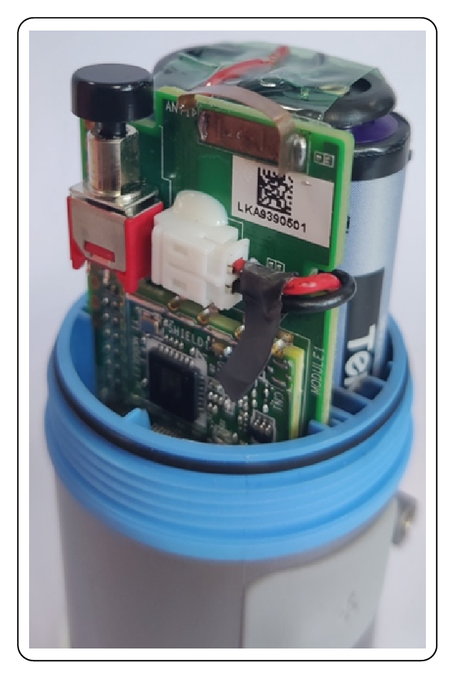
5. Re-attach the top chassis.
Solution overview
The AV300 sensor is a LoRaWAN asset tracking sensor which utilizes GPS for determining location. The sensor can be mounted on non-powered assets exposed to rain, dust, and marine conditions, where long battery life is required. The device has built-in antennas for GPS reception and for LoRaWAN communication, a 3D accelerometer, a high-performance GPS that can track both GPS and GLONASS satellites simultaneously, and flash memory for storing non-volatile information. The device also integrates with the dashboard geofence feature for location defined alerting.
Product image
AV300 Outdoor GPS Sensor
Key benefits
● Track assets such as vehicles, containers, trailers, and freight
● Detect unauthorized movement of the assets
Product details
Table 75. Cisco part number
| Geography |
Cisco PID |
| US, Canada |
IOTAV-L-GPS-L1-US |
| Europe |
IOTAV-L-GPS-L1-EU |
| Australia, New Zealand, Brazil, Argentina, Chile |
IOTAV-L-GPS-L1-AU |
| India |
IOTAV-L-GPS-L1-IN |
Table 76. Environmental/Physical specifications
| Specification |
Description |
| Operating Temperature |
-20 to 60°C (-4 to 140 °F) |
| Storage Temperature |
-20 to 60°C (-4 to 140 °F) |
| IP Rating |
IP67 |
| Dimensions (L x W x H) |
108 x 86 x 31 mm (4.25 x 3.38 x 1.22 inches) |
| Weight |
188 g (0.41 lbs) |
| Housing |
Ultra-rugged nylon glass |
Table 77. Radio
| Specification |
Description |
| Frequency Range |
800 MHz / 900 MHz ISM Band |
| Range |
Up to 15km (dependent on environment) |
Table 78. Location specifications
| Specification |
Description |
| Constellation |
Concurrent GPS/GLONASS |
| Channels |
72 |
| Tracking sensitivity |
-167 dBm |
Table 79. Battery
| Specification |
Description |
| Battery Type |
3x 1.5V AA in series (lithium-ion recommended) |
| Operating Voltage |
4V to 6V |
| Battery Life |
~5 years (1 location acquisition/day, 25C, max SF, and max Tx power) |
Telemetry reporting metrics
When motion is detected, sensor moves into “in trip” state with a default reporting interval of 15 minutes. When sensor has been stationary for at least 5 minutes, it moves into an “out of trip” state with a default reporting interval of 24 hours.
Data types reported by the sensor include: In trip/out of trip, Latitude/Longitude, Speed, Heading, Battery level.
Table 80. Product certification and compliance
| Specification |
Applicable regions |
| Safety |
|
| UL/CSA 60950-1/62368-1 |
North America |
| EN 60950-1/62368-1 |
EU |
| CB to IEC 60950-1 |
Worldwide |
| CB to IEC 62368-1 |
Worldwide |
| IEC 60529 (IP67) |
Worldwide |
| IEC 60950-22 |
Worldwide |
| EMC Immunity |
|
| EN 301489-1 |
EU |
| EN 301489-3 |
EU |
| Radio |
|
| EU 863-870 (EU) |
|
| EN 300220-1 |
EU |
| EN 300220-2 |
EU |
| CE RED |
EU |
| US 902-928 (USA, Canada) |
|
| FCC 47CFR Part 15 B and C |
USA |
| RSS210 |
Canada |
| IC ICES-003 |
Canada |
| AUS915 (LATAM, AU, NZ) |
|
| RCM approval AS/NZS4268 |
Australia, New Zealand |
| Anatel certification1 |
Brazil |
| Enacom certification |
Argentina |
| IN865 (India) |
|
| WPC certification |
India |
| Other |
|
| RoHS |
EU |
| FCC Part 2 |
USA |
| RSS 102 |
Canada |
Wireless statement
● Este equipamento não tem direito à proteção contra interferência prejudicial e não podecausar interferência em sistemas devidamente autorizados.
● This equipment is not entitled to protection against harmful interference and may not causeinterference in properly authorized systems.
EMC CISPR statement
● Este produto não é apropriado para uso em ambientes domésticos, pois poderá causarinterferências eletromagnéticas que obrigam o usuário a tomar medidas necessárias para minimizarestas interferências.
● This product is not suitable for use in a domestic environment as it may cause electromagneticinterference that requires the user to take necessary actions to minimize such interference.
Turning AV300 On/Off
Turning AV300 On/Off
● Turn on: Insert (3) 1.5V AA batteries.
● Turn off: Remove batteries.
● Allow about 10 seconds after turning off before turning on.
● LED indicator:
◦ When batteries are inserted: Flash for 1 second.
◦ If brownout condition is detected, LED illuminates for 10s. Please insert new batteries.
◦ Sensor attempts to join network. LED flashes 2 times per second. Join may fail, in which case, LED turns off for some time and then retries the join process.
◦ Sensor attempts to acquire GPS fix (may take up to a few minutes). LED flashes 1 time per second during fix time.
◦ Sensor sends GPS fix. LED flashes 2 times.
◦ LED off for the duration of operation.
Mounting Accessories and Methods AV300
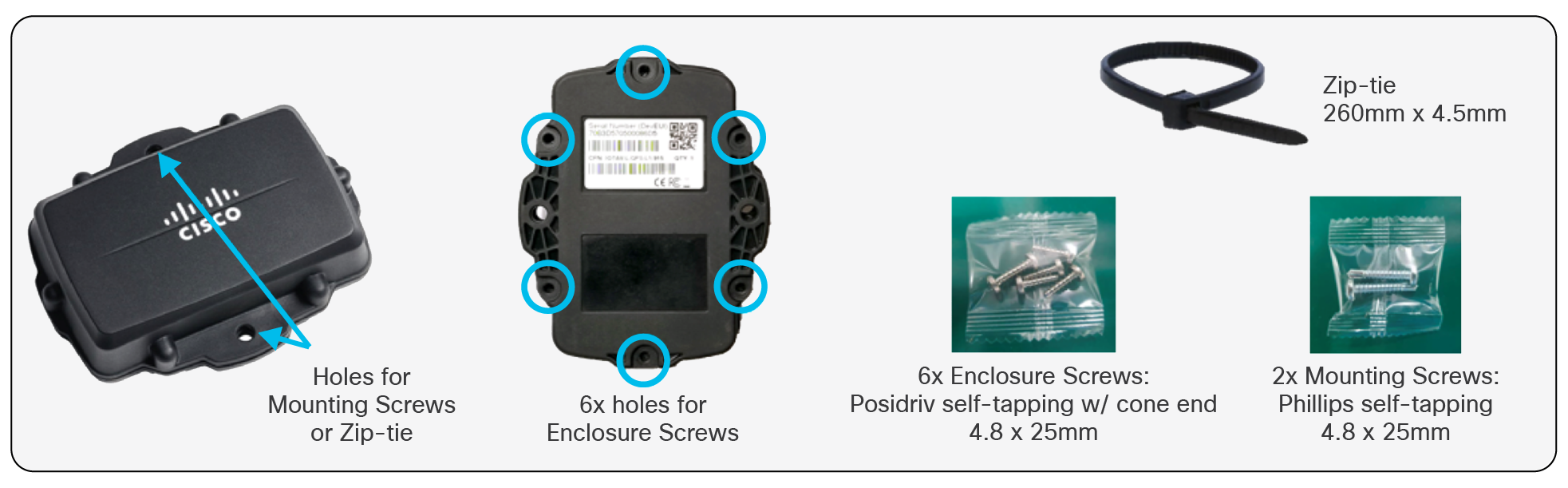
Mounting Accessories and Methods AV300
● Fasten back cover to outer shell using 6x enclosure screws.
● Attach to wall or other flat surface using 2x mounting screws.
● Attach via included zip-tie.
◦ Included zip-tie is intended for pole size with diameter up to 85mm.
12. AV400: Industrial Sensor Bridge
Solution Overview
The AV400 Industrial Sensor Bridge enables the user to convert industry-standard analog or digital sensor signals to LoRaWAN.
The AV400 is intended for use with Cisco Industrial Asset Vision (IAV) and provides flexibility to 3rd party sensors outside of the IAV core sensor catalog. The AV400 is ideal for applications such as monitoring tank levels, pressure, flow, current, and more.
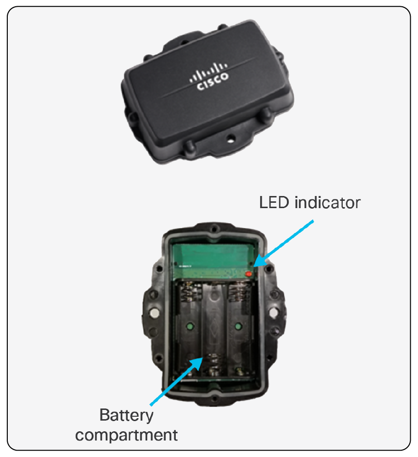
Product Image
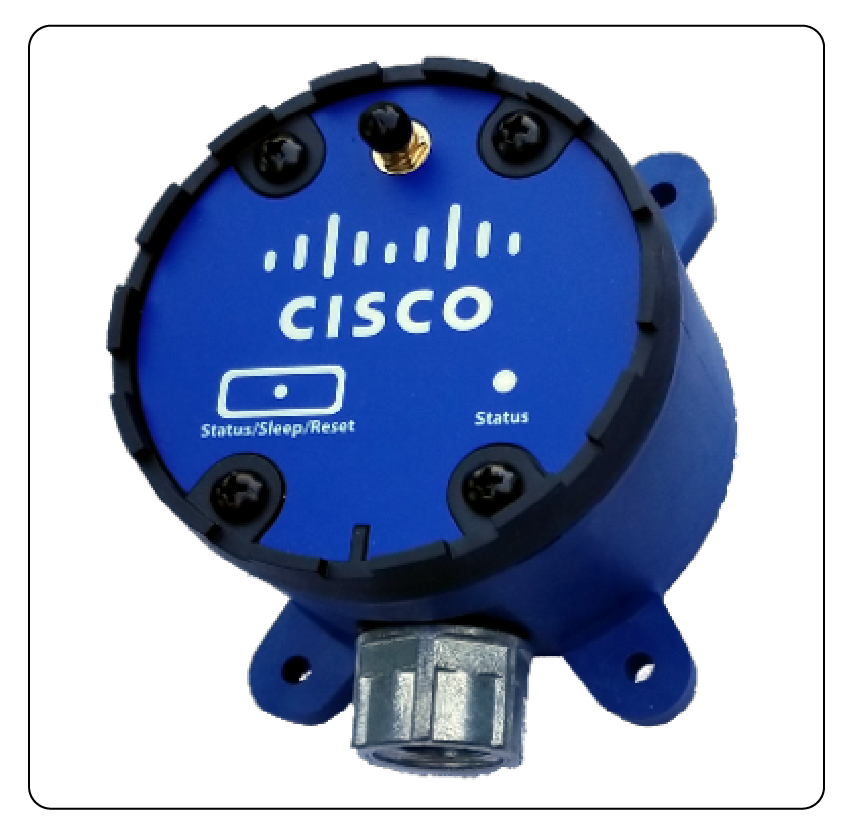
AV400 LoRaWAN Wireless Condition Monitoring Sensor
Key Benefits
● Long-range wide area IoT application
● Provides connectivity to industry-standard analog or digital sensors
● Rugged, IP66-rated, fiber-reinforced polyester PBT enclosure
Product Details
Table 81. Cisco Part Numbers
| Geography |
Cisco PID |
| US, Canada |
AV400-BRI-US |
| Europe |
AV400-BRI-EU |
| Australia, New Zealand, Brazil, Argentina, Chile |
AV400-BRI-AU |
Table 82. Power Specifications
| Specification |
Description |
| Internal |
Two 3.6V ER14505 AA batteries*
*Battery powering is not supported at the current time; Contact Cisco for more details.
|
| External, Wired Power |
9 ~ 36 VDC Steady state power consumption (typical): 144mW @ 24V Power consumption during transmission time (typical): 0.6W @ 24V (Condition: 20 degC, spreading factor=10, US915, maximum transmit power) |
Table 83. Environmental/Physical Specifications
| Specification |
Description |
| Operating Temperature |
-40 to +75°C (-40 to +167°F) |
| Storage Temperature |
-40 to +85°C (-40 to +185°F) |
| Operating Humidity |
10 ~ 95% non-condensing |
| Storage Humidity |
10 ~ 95% non-condensing |
| Physical Connection |
12.7-mm (1/2") conduit or cable-gland (not included) Two sensor interface cables included; 8-wire, 26 AWG, 1m (39 in) |
| Mounting |
Magnetic mounting via an internal magnet, Holding force = 2.13 kg (4.7 lbs) Four mounting ears, M5 (#10) |
| Enclosure |
IP66-rated, fiber-reinforced polyester PBT |
| Weight |
400 g (0.88 lbs) |
Table 84. Radio Specifications
| Specification |
Description |
| Frequency Band |
AV400-BRI-US: 902-928MHz ISM Band AV400-BRI-EU: 863-870MHz ISM Band AV400-BRI-AU: 915-928MHz ISM Band |
| Rx Sensitivity |
-137dBm |
| Tx Power (conducted) |
AV400-BRI-US: 18.9dBm AV400-BRI-EU: 14.4dBm AV400-BRI-AU: 18.9dBm |
| External Antenna |
RP-SMA, omnidirectional 1.7dBi Length: 170 mm (6.69") |
| Range |
Up to 10km (6.213 miles) (dependent on environment) |
Table 85. Digital Inputs
| Specification |
Description |
| Voltage Range |
Dry contact: Logic level 1: 0 ~ 1V; Logic level 0: open Wet contact: Logic level 1: 0 ~ 1 VDC; Logic level 0: 3 ~ 30 VDC Note: Inputs are active low, as reflected above. |
| Pull-Up Current |
32 μA |
| Isolation |
None |
| Channels |
2 (DI1 and DI2) |
Table 86. Analog Inputs
| Specification |
Description |
| Input Range |
Analog Inputs 1 & 2: 0 – 20mA Analog Inputs 3 & 4: 0 – 10V |
| Resolution |
16 bit |
| Input Load Resistance |
10MΩ (voltage), 120Ω (current) |
| Accuracy |
±0.1% (Voltage) at +25 °C ±0.2% (Current) at +25 °C |
Table 87. Reporting Metrics
| Monitoring |
Default Reporting Interval |
| AI1-4, DI1-2 |
Measured together every 15 mins |
| Battery |
6 hours |
Table 88. Product Certification and Compliance
| Specification |
Applicable regions |
| Safety |
|
| UL/CSA 62368-1 |
North America |
| EN/IEC 62368-1 Ed 3 |
Worldwide |
| IEC 60529 (IP66) |
Worldwide |
| EMC Immunity |
|
| EN 301489-1/-3 |
EU |
| Radio |
|
| EU 863-870 (EU) |
|
| EN 300220-1/-2 |
EU |
| CE |
EU |
| US 902-928 (USA, Canada) |
|
| FCC 47 CFR Part 15 Subpart B |
USA |
| FCC 47 CFR Part 15 Subpart C |
USA |
| FCC 47 CFR 15.247 |
USA |
| RSS247 |
Canada |
| ICES-003 |
Canada |
| AU 915-928 (LATAM, AU, NZ) |
|
| RCM approval AS/NZS4268 |
Australia, New Zealand |
| Anatel certification1 |
Brazil |
| Enacom certification |
Argentina |
| Other |
|
| EN62311, RoHS |
EU |
| FCC 47 CFR Part 2 |
USA |
| RSS 102 |
Canada |
Wireless statement
● Este equipamento não tem direito à proteção contra interferência prejudicial e não pode causar interferência em sistemas devidamente autorizados.
● This equipment is not entitled to protection against harmful interference and may not cause interference in properly authorized systems.
EMC CISPR statement
● Este produto não é apropriado para uso em ambientes domésticos, pois poderá causar interferências eletromagnéticas que obrigam o usuário a tomar medidas necessárias para minimizar estas interferências.
● This product is not suitable for use in a domestic environment as it may cause electromagnetic interference that requires the user to take necessary actions to minimize such interference.
Dimensions
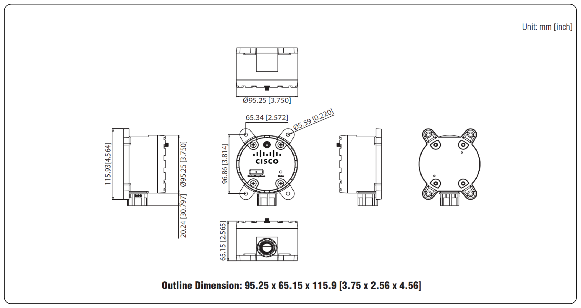
AV400 Dimensions
Device Description
Overview
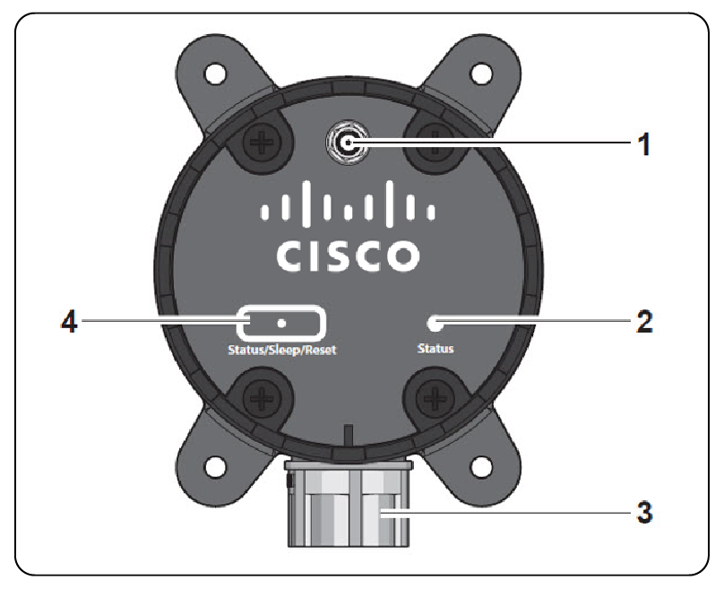
AV400 Overview
1. Antenna connector
2. Status LED
3. Cable conduit
4. Status/Sleep/Reset button
Turning AV400 On/Off and Button/LED Behavior
To turn on the AV400, apply power to it; conversely, removing power turns it off.
When the device turns on, it will enter a 5-minute waiting period before attempting to register with the IAV cloud service. This is indicated by a fast blinking of the LED. To avoid the 5-minute waiting period, quickly press/release the button. Note that the registration process will be successful only if the device has first been onboarded with the IAV mobile application.
Once the device starts attempting to register, the LED behavior is shown in the following table.
Table 89. Startup LED Behavior
| LED Behavior |
Description |
| Illuminates solid for 3 seconds (first time) |
Registration attempts have started. |
| Illuminates solid for 3 seconds (second time) |
Registration has been successful. |
| Flashes quickly for 10 seconds |
Indicates that repeated registration attempts have been unsuccessful. This occurs after each failed registration sequence. For the -US and -AU PIDs, a registration sequence is defined as one attempt at a low LoRaWAN spreading factor (suitable for closer range) and one attempt at a higher spreading factor (needed for longer range). For the -EU PID, a registration sequence is defined as one attempt at each spreading factor from SF7 to SF12. Note: The device will continue trying to register; the LED flashing is just an indication that the device is having problems registering. |
Once in normal operation, press/release the button quickly to initiate an immediate sampling of data and associated data report to the cloud. The LED behavior in this scenario is described in the following table.
Table 90. Manually triggered report LED Behavior
| LED Behavior |
Description |
| Single fast blink |
Manually triggered data report has been initiated and will be sent within a few seconds. |
| Several blinks for 10 seconds |
Note: This behavior only applies to regions which require duty cycle compliance (the -EU PID of the AV400). Desire to send a manually triggered data report has been received, but device is not allowed to send it immediately due to regional duty cycle constraints. Message will be sent as soon as possible. Expected time to wait is between ~10 seconds and ~2.5 minutes. In this waiting time, do not continuously press the button. |
To reset the unit, press/hold the pushbutton for 5 seconds before releasing. The AV400 will reload back to the initial state of attempting to register with the cloud service.
Installation/Mounting
Wall mounting
1. Locate the area to install and mark the four screw locations. If needed, drill pilot holes. If installing in concrete, it is recommended to use wall sinks.
2. Align the device to the holes (or markings) and secure with screws of less than 5mm in diameter.
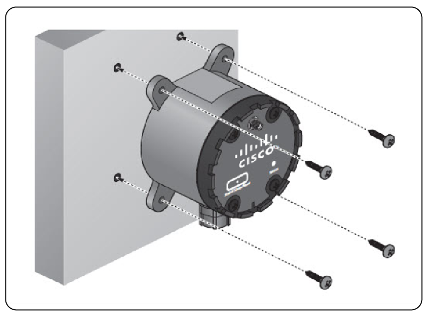
AV400 Wall mounting
Routing data cables
1. Loosen the four front cover screws and remove front cover.
2. Insert the sensor cables through the channel on the device. The two cables are physically and electrically identical. It can be helpful to place a piece of tape (or similar) on the ends of one cable so that you can differentiate between the two cables in later steps.
Note: Position the cable connector for each cable so that it can be connected to the circuit board.
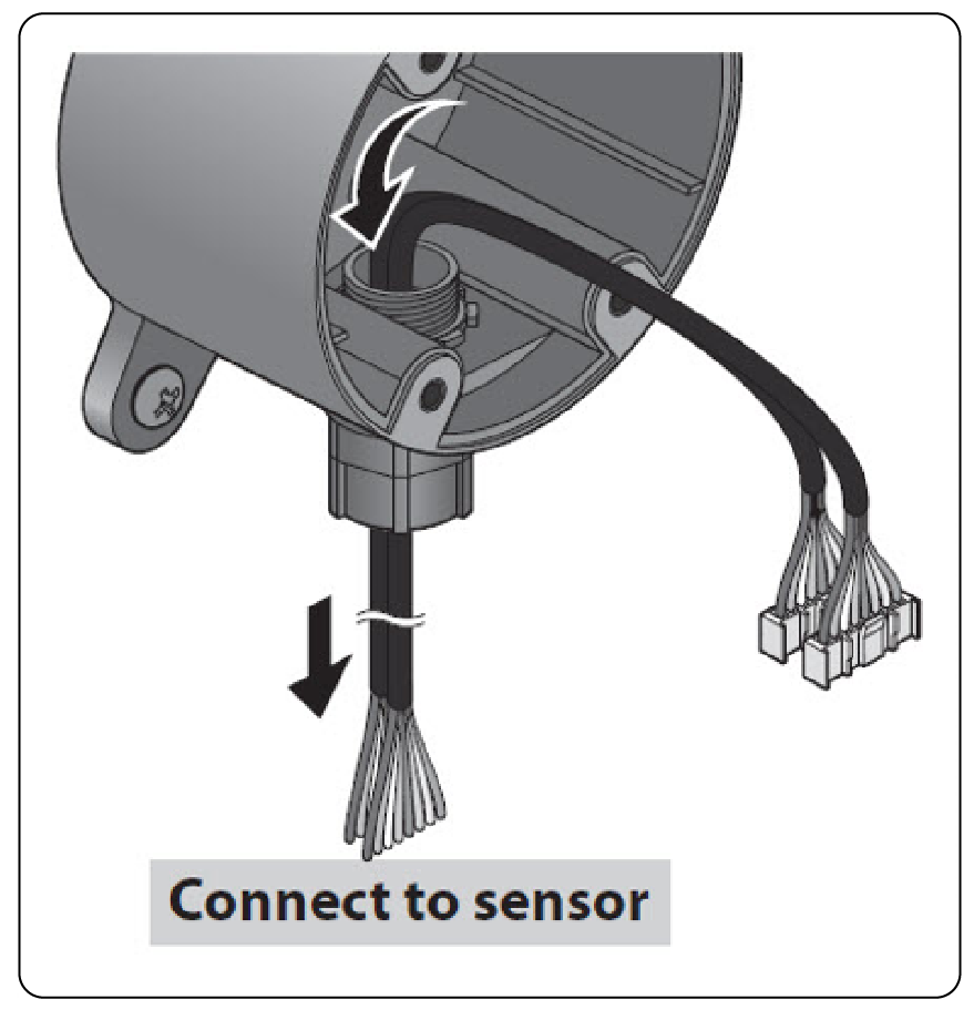
AV400 Routing data cables
3. Connect the sensor cables to the connectors on the device.
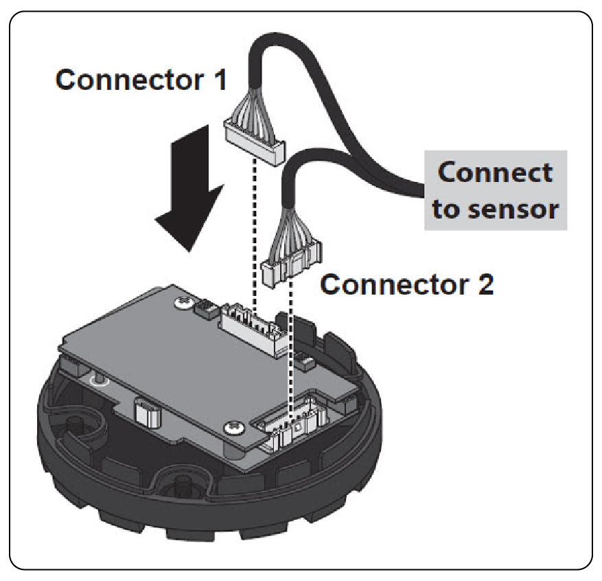
AV400 Connecting data cables
4. Align the top cover with the base and install while gently pulling the data cable slack. If there is resistance when pulling, do not pull the cable further to avoid damaging the connector.
5. Secure the top cover with the screws.
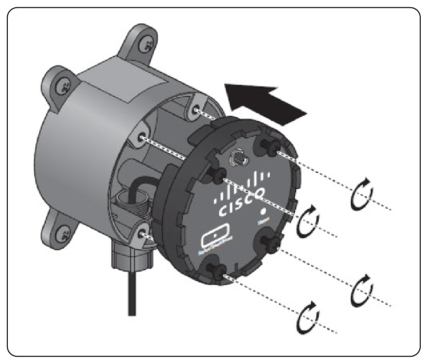
AV400 Reassemble housing
Install the antenna
Connect the antenna by rotating the antenna connector in the clockwise direction.
Note: Positioning of the antenna is crucial for effective wireless connectivity.
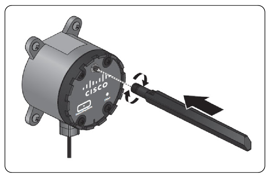
AV400 Install the antenna
Wiring Diagram
The following table defines each of the breakout cable wires based on wire color.
| Wire Color |
Connector 1 Cable |
Connector 2 Cable |
| Definition |
Definition |
|
| Gray |
AI1 |
PWR |
| White |
GND |
V- |
| Blue |
AI2 |
DI1 |
| Green |
GND |
GND |
| Yellow |
AI3 |
DI2 |
| Pink |
GND |
GND |
| Red |
AI4 |
NC (No Connect) |
| Brown |
GND |
GND |
Note: All signals labeled “GND” and “V-“ are non-isolated (electrically equivalent).
Wiring examples
4-20mA Sensor Wiring Reference Example
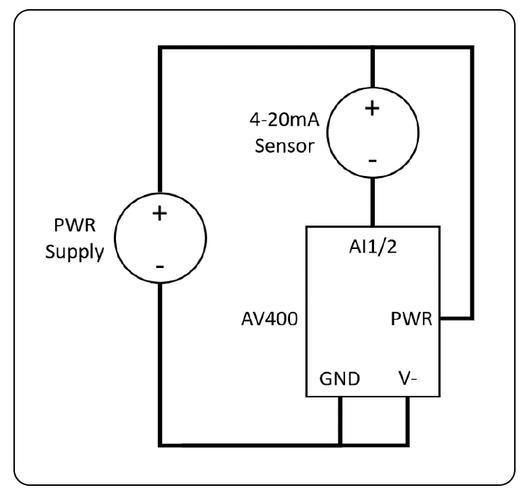
AV400 4-20mA Sensor Wiring Reference Example
0-10V Sensor Wiring Reference Example
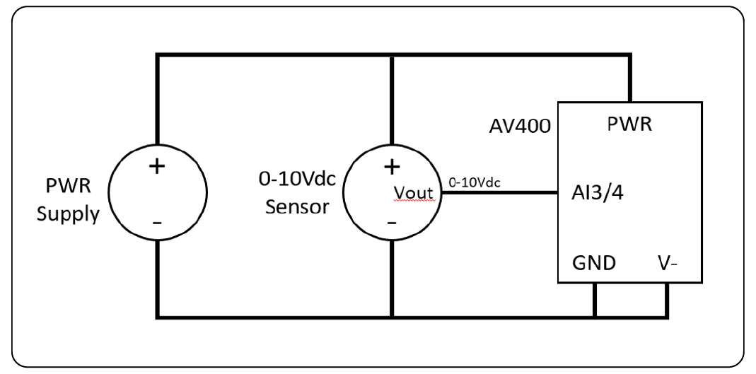
0-10V Sensor Wiring Reference Example
Digital Input Dry Contact Wiring Reference Example
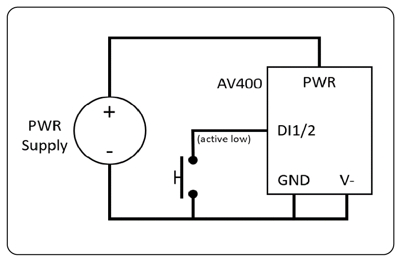
AV400 Digital Input Dry Contact Wiring Reference Example
Cisco Industrial Asset Vision is provided with two components: (1) one-time hardware purchase for sensors and gateways, and (2) SaaS subscription metered on each sensor to be connected in 1-, 3-, or 5-year terms.
A Cisco Industrial Asset Vision subscription is purchased using the IOTAV-BUNDLE-US, IOTAV-BUNDLE-EU, IOTAV-BUNDLE-IN, or IOTAV-BUNDLE-AU Multiline Bundle (MLB), depending on geographic region.
Table 91. Ordering multiline bundles
| Part number |
Description |
Geography or region |
| IOTAV-BUNDLE-US |
Industrial Asset Vision bundle |
North America (US915) |
| IOTAV-BUNDLE-EU |
Industrial Asset Vision bundle |
Europe (EU868) |
| IOTAV-BUNDLE-AU |
Industrial Asset Vision bundle |
Australia, New Zealand, Brazil, Argentina, Chile (AU915) |
| IOTAV-BUNDLE-IN |
Industrial Asset Vision bundle |
India (IN865) |
Table 92. Ordering gateway hardware
| Part number |
Description |
Geography or region |
| IXM-LPWA-900-16-K9 |
Cisco wireless gateway for LoRaWAN |
North America (US915) and Australia, New Zeland, Brazil, Argentina, Chile (AU915) |
| IXM-LPWA-800-16-K9 |
Cisco wireless gateway for LoRaWAN |
Europe (EU868) and India (IN865) |
Table 93. Ordering sensor hardware
| Part number |
Description |
Geography or region |
| IOTAV-L-GPS-L1-US IOTAV-L-GPS-L1-EU IOTAV-L-GPS-L1-AU IOTAV-L-GPS-L1-IN |
Cisco Outdoor GPS Sensor |
LoRaWAN 900 MHz (US915) LoRaWAN 800 MHz (EU868) LoRaWAN 900 MHz (AU915) LoRaWAN 800 MHz (IN865) |
| IOTAV-L-ENV-O1-US IOTAV-L-ENV-O1-EU IOTAV-L-ENV-O1-AU IOTAV-L-ENV-O1-IN |
Cisco Outdoor Temp/Humidity Sensor |
LoRaWAN 900 MHz (US915) LoRaWAN 800 MHz (EU868) LoRaWAN 900 MHz (AU915) LoRaWAN 800 MHz (IN865) |
| IOTAV-L-ENV-I1-US IOTAV-L-ENV-I1-EU IOTAV-L-ENV-I1-AU IOTAV-L-ENV-I1-IN |
Cisco Indoor Temp/Humidity Sensor |
LoRaWAN 900 MHz (US915) LoRaWAN 800 MHz (EU868) LoRaWAN 900 MHz (AU915) LoRaWAN 800 MHz (IN865) |
| IOTAV-L-PTM-I1-US IOTAV-L-PTM-I1-EU IOTAV-L-PTM-I1-AU IOTAV-L-PTM-I1-IN |
Cisco Product Temperature Sensor |
LoRaWAN 900 MHz (US915) LoRaWAN 800 MHz (EU868) LoRaWAN 900 MHz (AU915) LoRaWAN 800 MHz (IN865) |
| IOTAV-L-FRZ-O1-US IOTAV-L-FRZ-O1-EU IOTAV-L-FRZ-O1-AU IOTAV-L-FRZ-O1-IN |
Cisco Refrigerator Temp/Humidity Sensor |
LoRaWAN 900 MHz (US915) LoRaWAN 800 MHz (EU868) LoRaWAN 900 MHz (AU915) LoRaWAN 800 MHz (IN865) |
| IOTAV-L-HAL-I1-US IOTAV-L-HAL-I1-EU IOTAV-L-HAL-I1-AU IOTAV-L-HAL-I1-IN |
Cisco Door/Window Sensor |
LoRaWAN 900 MHz (US915) LoRaWAN 800 MHz (EU868) LoRaWAN 900 MHz (AU915) LoRaWAN 800 MHz (IN865) |
| IOTAV-L-WLK-O1-US IOTAV-L-WLK-O1-EU IOTAV-L-WLK-O1-AU IOTAV-L-WLK-O1-IN |
Cisco Water Leak Sensor |
LoRaWAN 900 MHz (US915) LoRaWAN 800 MHz (EU868) LoRaWAN 900 MHz (AU915) LoRaWAN 800 MHz (IN865) |
| IOTAV-L-LUX-I1-US IOTAV-L-LUX-I1-EU IOTAV-L-LUX-I1-AU IOTAV-L-LUX-I1-IN |
Cisco Light Level Sensor |
LoRaWAN 900 MHz (US915) LoRaWAN 800 MHz (EU868) LoRaWAN 900 MHz (AU915) LoRaWAN 800 MHz (IN865) |
| IOTAV-L-MTM-O1-US IOTAV-L-MTM-O1-EU IOTAV-L-MTM-O1-AU IOTAV-L-MTM-O1-IN |
Cisco Machine Temperature Sensor |
LoRaWAN 900 MHz (US915) LoRaWAN 800 MHz (EU868) LoRaWAN 900 MHz (AU915) LoRaWAN 800 MHz (IN865) |
| IOTAV-L-OCU-I1-US IOTAV-L-OCU-I1-EU IOTAV-L-OCU-I1-AU IOTAV-L-OCU-I1-IN |
Cisco Indoor Occupancy Sensor |
LoRaWAN 900 MHz (US915) LoRaWAN 800 MHz (EU868) LoRaWAN 900 MHz (AU915) LoRaWAN 800 MHz (IN865) |
| AV251-VIB-US AV251-VIB-EU AV251-VIB-AU |
Cisco Vibration Monitoring Sensor |
LoRaWAN 900 MHz (US915) LoRaWAN 800 MHz (EU868) LoRaWAN 900 MHz (AU915) |
| AV400-BRI-US AV400-BRI-EU AV400-BRI-AU |
Cisco Industrial Sensor Bridge |
LoRaWAN 900 MHz (US915) LoRaWAN 800 MHz (EU868) LoRaWAN 900 MHz (AU915) |
Information about Cisco’s environmental sustainability policies and initiatives for our products, solutions, operations, and extended operations or supply chain is provided in the “Environmental Sustainability Approach” section of Cisco’s Corporate Social Responsibility (CSR) Report.
Reference links to information about key environmental sustainability topics (mentioned in the “Environmental Sustainability Approach” section of the CSR Report) are provided in the following table.
Table 94. Environmental sustainability information
| Sustainability topic |
Reference |
| Information on product-material-content laws and regulations |
|
| Information on electronic waste laws and regulations, including products, batteries, and packaging |
Reference links to product-specific environmental sustainability information that is mentioned in relevant sections of this data sheet are provided in the following table.
Table 95. Product-specific environmental sustainability information
| Sustainability topic |
Reference |
| General |
|
| Eco-Design Compliance (EU ErP Lot, Etc.) Environmental Certifications (EPEAT, Energy Star, Etc.) |
Table AA. Product Compliance Table BB. Product Compliance or Platform Features/Benefits |
| Power |
|
| Idle, Typical or Max Product Power Hardware Enabled Energy Features |
Table CC. Product Specifications Table DD. Platform Features/Benefits |
| Software Enabled Energy Features Power Supply Information Power Calculator |
Table EE. Platform Features/Benefits Table FF. Product Specifications Table GG. Product Specifications |
| Material |
|
| Unit Weight System Weight (Product + Packaging) Recycled Content |
Table HH. Product Specifications Table II. Product Specifications Table JJ. Product Specifications |
Cisco makes the packaging data available for informational purposes only. It may not reflect the most current legal developments, and Cisco does not represent, warrant, or guarantee that it is complete, accurate, or up to date. This information is subject to change without notice.
Flexible payment solutions to help you achieve your objectives
Cisco Capital makes it easier to get the right technology to achieve your objectives, enable business transformation and help you stay competitive. We can help you reduce the total cost of ownership, conserve capital, and accelerate growth. In more than 100 countries, our flexible payment solutions can help you acquire hardware, software, services and complementary third-party equipment in easy, predictable payments. Learn more.
Drive better, safer and more efficient operations – from anywhere
Learn more about Cisco Industrial Asset Vision at www.cisco.com/go/iav.
| New or revised topic |
Described in |
Date |
| AU and IN SKUs added |
Wireless Vibration Monitoring Sensor |
October 2021 |
| Vibration Sensor and Sensor Bridge added |
Industrial Sensor Bridge |
January 2023 |