Cisco Nonstop Forwarding with Stateful Switchover (NSF with SSO) provide extraordinary resiliency benefits. At times, the resiliency goals may seem at odds with routing protocol convergence tuning mechanisms. Care should be taken to match network design goals with Interior Gateway Protocol (IGP) timer settings.
Cisco NSF with SSO is a Cisco innovation for systems with dual route processors. Cisco NSF with SSO allows a router that has experienced a hardware or software failure of an active route processor to maintain data link layer connections and to continue forwarding packets during the switchover to the standby route processor. This forwarding can continue despite the loss of routing protocol peering arrangements with other routers. Routing information is recovered dynamically in the background, while packet forwarding proceeds uninterrupted.
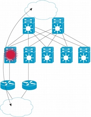
Figure 1.
NSF with SSO Seeks to Preserve Traffic Forwarding
For the purpose of this document, Interior Gateway Protocol (IGP) timer manipulation refers to the practice of reducing HELLO and HOLD-TIME* timers in Open Shortest Path First (OSPF), Intermediate-System to Intermediate-System (ISIS), or Enhanced Interior Gateway Routing Protocol (EIGRP) in order to reduce the amount of time required to detect a failed routing neighbor. In turn, this enables the network to converge more quickly during a link or router failure.
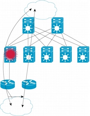
Figure 2.
Fast Convergence Seeks to Shift Traffic Quickly to an Alternate Path
Initially, it appears that Cisco NSF and OSPF/ISIS/EIGRP timer manipulation have complimentary objectives. Each feature is dedicated to achieving the fastest possible convergence in the event of a failure on a router. However, more careful analysis reveals that these technologies also have conflicting goals. Cisco NSF attempts to maintain the flow of traffic through a router that has experienced a failure; conversely, OSPF/ISIS/EIGRP timer manipulation tries to quickly redirect the flow of traffic away from a router that has experienced a failure towards an alternate path. While not mutually exclusive, the two technologies try to address different aspects of the same problem in disparate ways. It is therefore important to carefully consider the network design goals and establish precedence for redundancy.
At specific network points you may choose to maintain the current transmission path through a router, taking advantage of redundant route processor hardware; at other points in the network, you can choose to reroute traffic according to the IGP. The network designer may choose the method that maximizes service and minimizes packet loss for each specific environment or portion of the network.
* Terminology note: in both OSPF, ISIS, and EIGRP neighbor adjacency is maintained by the periodic transmission of HELLO packets. Both protocols support the concept a neighbor should be declared unavailable if it does not transmit a HELLO within a certain time interval. It is this latter time interval that has confusing terminology associated with it. In OSPF, it is usually referred to as the "dead-interval". In ISIS, the term "hold timer" is used. EIGRP uses the term HoldTime. However, it is also known by additional variations, including the dead timer or holddown timer; this depends on the context. For the purposes of this paper, when specifically referring to OSPF, the timer will be called the dead-interval; when referring to ISIS, EIGRP, or in general discussion of networking concepts, the timer will be referred to as the hold-time timer.
In order to provide some guidelines and data for network designers to make informed decisions regarding path resiliency, a series of tests were performed by the Cisco End-To-End System Test (E2EST) organization and the Enterprise Solutions Engineering (ESE) group. The tests provided information and confirmed ability of Cisco NSF to decrease convergence time when OSPF/ISIS/EIGRP timers have been manipulated. This paper summarizes those test results and makes recommendations.
Note that combining OSPF/ISIS timer manipulation and Cisco NSF might not be the most common deployment environment. OSPF/ISIS timer manipulation is designed to improve convergence time in a multi-access network (ie: several IGP routing peers sharing a common broadcast media, such as Ethernet). The primary deployment scenario for Cisco NSF with SSO is at the edge of the Service Provider network, where the data-link layer generally consists of point-to-point links to Enterprise customers and redundant high-speed point-to-point links (such as POS or Gigabit Ethernet) to the Service Provider distribution layer. A second deployment point is at the Enterprise network edge. Again, the data-link layer generally consists of point-to-point links to Service Providers and redundant Gigabit Ethernet point-to-point links to the campus infrastructure.
Manipulating protocol timers has very little effect in this point-to-point environment, because link-status is a more expedient method of detecting a neighbor failure. The IGP will immediately declare its neighbor unavailable upon the detection of a link-flap on a point-to-point link, and will begin the process of reconvergence. Thus, there is no reason to set protocol timers, because the detection of a link failure supercedes them in a point-to-point deployment.
As Cisco NSF functionality is ported onto other hardware products, most notably the Cisco Catalyst® 6500 Series Switch, Cisco expects that multi-access networks will become a more common deployment scenario. Therefore, this testing is a necessary "first look" at compatibility between Cisco NSF and OSPF/ISIS/EIGRP timer manipulation.
CISCO NSF WITH SSO TESTING WITH VARIOUS IGP TIMER SETTINGS
The Cisco E2EST organization conducted a series of tests to explore the relationship of Cisco NSF with SSO and IGP Hello and Hold-Time settings. These tests determined the minimum settings for the HELLO and HOLD-TIME timers in OSPF and ISIS, which allowed traffic flow to continue along the current physical path without routing protocol reconvergence. This was validated by passing traffic through an NSF-capable router (on which OSPF or ISIS timers had been lowered) and forcing a switchover to a redundant Route Processor. If the transit traffic continued to flow through the NSF-capable router, the test was given a grade of "met design criteria". If traffic was redirected to an alternate path, the test was marked as "did not meet design criteria".
This test assumes that the desired behavior is for all traffic to remain with the NSF-capable router. While switching over to an alternate path may be considered acceptable behavior, it has certain drawbacks:
• New Link-State Advertisements (LSAs) are issued, causing network reconvergence. This may cause some churn in large networks, especially when OSPF or ISIS acts as the IGP for BGP. Not only must the IGP network reconverge, but BGP route selection might need to be reinitiated.
• The NSF-capable router could be the primary path for both multi-homed destinations, and singly-homed routes. In other words, the NSF-capable router might be the sole path in the network for certain destinations. Traffic redirected away from the NSF-capable router would be dropped; this behavior would be undesirable.
It should be noted that multi-homed traffic still gets to its final destination, even when traffic switches over to a redundant router. Thus, it is a misnomer to refer to this result as a "failure". Instead, it might be more appropriate to say that the router did not "exhibit the expected behavior". This is why the terms "[met/did not meet design] test criteria", rather than the more pejorative "Pass/Fail", are used.
HARDWARE, INTERFACES, VERSIONS, AND SCALING
The Units Under Test (UUT) were the three NSF-capable routers: Cisco 12000 and 10000 Series Internet Routers and the Cisco 7500 Series Routers. Cisco IOS® Software Release 12.0(22)S was deployed on all routers.
In each test, slightly more than five thousand OSPF or ISIS routes were injected into the test bed. One series of tests increased this number to 14,000 routes, in order to understand if the total number of routes had any effect on the outcome of the tests.
Details concerning the number and type of interfaces in use during the tests are provided below:
Cisco 12000 Series Internet Routers
• 3 OC48 POS controllers (3 POS)
• 3 Packet over SONET network interface(s)
• 4 Single Port Gigabit Ethernet/IEEE 802.3z controllers (4 GigabitEthernet)
• 3 GigabitEthernet/IEEE 802.3 interface with 18 sub interfaces
• 2 Packet over SONET network interface(s)
• 3 Channelized T3 port
• 70 PPP interfaces
• 110 FR interfaces
TEST BED SETUP
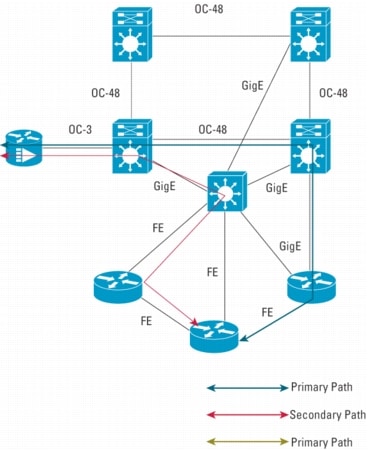
Figure 3 depicts the test bed that was constructed to perform these tests. A primary route, providing the best (lowest cost) OSPF or ISIS route was configured. This path traversed the NSF-capable router. A secondary path allowed traffic to reach the ultimate destination if the primary path was lost. This path bypassed the NSF-capable router.
Traffic was monitored at different points in the network, in order to validate that it continued to traverse the primary path. If traffic switched to the secondary path, the test was labeled as "did not meet design test criteria".
Figure 3.
Timer Manipulation Test Bed
TEST RESULTS
ISIS Results
ISIS maintains neighbor relationships with other routers via the transmittal of periodic HELLO packets. The rate at which these HELLO packets are sent is configured via the "isis hello-interval seconds {level-1 | level-2}" command.
ISIS also maintains a hold-time timer, which allows it to identify a failure in a neighbor router. The hold-time is determined by multiplying the hello-interval timer with the hello-multiplier value. The hello-multiplier is configured with the "isis hello-multiplier multiplier {level-1 | level-2}" command.
To determine the failover time, multiply the hello-interval by the hello-multiplier. For example, a router with a hello-interval of 3 and a hello-multiplier of 4 would be able to detect a failed neighbor and begin reconvergence in 12 seconds.
Cisco has two different implementations of NSF for ISIS, so two series of tests were performed for all hardware: Cisco ISIS/IETF NSF which required protocol changes on the neighbor routers, and Cisco ISIS/NSF, which takes a stateful approach and does not require protocol changes on the peer routers.
All ISIS test cases were performed using ~5,000 ISIS routes. Most currently deployed ISIS networks have fewer than 5,000 total routes. Thus, this number was chosen as a "worst-case" scenario and illustrates the scalability of the solution.
ISIS Results Analysis
The combination of Cisco NSF and timer manipulation for ISIS works very much as expected. The tests produced the desired results in almost all cases. The transit traffic remained with the NSF router and did not reconverge to an alternate path.
All test configurations worked as expected on the Cisco 12000 and Cisco 10000 Series Internet Routers. The combination of hello-interval and hello-multiplier could be reduced to 1 and 3 respectively. This provides three-second reconvergence in the case of a failed link or router, and Cisco NSF can still operate properly.
Furthermore, the implementation (Cisco-specific versus IETF implementation) did not appear to affect the results. In both cases, all tests produced the expected results.
When the Cisco 7500 Series Router is configured for NSF, the tests showed the combination of hello-interval and hello-multiplier must meet or exceed six seconds with the Cisco 7500 Series Routers. This was expected behavior, based upon the known properties of the Cisco 7500 Series Routers using Cisco NSF. These results are consistent with the testing done at the time of the first release of Cisco NSF by Miercom Labs. That report concluded that the Cisco 7500 Series Router average recovery time after an NSF switchover was six seconds. For additional details, please see the Miercom Testing Validation Summary Report:
OSPF, like ISIS, maintains neighbor relationships with other routers via the transmittal of periodic HELLO packets. The rate at which these HELLO packets are sent is configured via the "ip ospf hello-interval seconds" command.
OSPF also maintains a dead-interval timer, allowing it to identify failure in a neighbor router. If the dead-interval is not explicitly configured, it defaults to 4 times the hello-interval. However, unlike ISIS, the OSPF dead-interval can be configured independently of the hello-interval. The "ip ospf dead-interval seconds" command is used to configure the dead-interval.
OSPF Results Analysis
OSPF timer manipulation tests produced interesting results. At first it appeared that NSF and timer manipulation for OSPF did not interoperate well. While some test cases passed when the dead-interval was as low as twenty-one seconds, it was not until the dead-interval was greater than or equal to twenty-six seconds that a consistent behavior could be observed. This behavior seemed hardware-independent, as similar results were observed on the Cisco 12000 and 10000 Series Internet Routers, and the Cisco 7500 Series Router.
An initial hypothesis was that the HELLO packets from the restarting router to all of its peers might not be arriving in time to maintain the neighbor relationship. However, Cisco NSF uses a Fast Hello algorithm that should begin sending HELLO packets very quickly at two-second intervals after switchover.
Further research revealed that two significant timers influenced the results:
• NSF-wait timer: contained within the OSPF process that delays the start of Out-of-Band resynchronization (OOB-Resynch) for an arbitrary amount of time (OOB-Resynch is the process by which the restarting router reinitializes its Link State Database, with help from neighbor routers). This timer allows the router enough time to receive HELLO packets from its neighbor routers on all of its interfaces, prior to beginning the resynchronization process. The default for this timer is twenty seconds.
• OOB-Resync timer: exists on the NSF-Aware neighbors of the restarting router. It is the maximum amount of time that neighbor will wait for the OOB-Resynch to begin with the restarting router before declaring the restart process a failure, resetting the neighbor relationship and reverting to "normal" OSPF. By default, this timer is set equal to the configured dead-interval timer.
Given that the OOB-Resync timer is tied to the dead-interval timer, when the dead-interval is lowered to achieve faster convergence, the OOB-Resync timer is similarly adjusted. At the time that these tests were performed, there was no published or hidden command available to set the OOB-Resync timer independently of the dead-interval timer.
An impossible task was attempted when the NSF-Wait timer was set at its default of twenty seconds, and the OOB-Resync timer was lowered to less than twenty seconds. The NSF-aware neighbor required the completion of the OOB-Resync process before the NSF-capable router could initiate the process. The OOB-Resync timer is guaranteed to expire prior to the beginning of the OOB-Resync. In turn, this means that the NSF-aware neighbor will reset the neighbor relationship.
Cisco modified the implementation as a result of this testing. These changes appeared in Cisco IOS Software Releases 12.0(25)S and 12.2(15)T1:
• The OOB-Resync timer is set to the maximum value of either the dead-interval timer or forty seconds. For example, if the dead-interval timer is set to a value lower than forty seconds, the OOB-Resync timer will still be forty seconds. Conversely, if the dead-interval timer is raised to some value greater than forty seconds (for some reason specific to an individual network configuration) then the OOB-Resync timer will be set to the same value. This occurs automatically, and requires no special configuration on the router
• A new CLI command has been introduced, which allows explicit configuration of the OOB-Resync timer: "ip ospf resync-timeout seconds". If desired, this command can be enabled on the NSF-aware peers of the restarting router. The command is enabled on a per-interface basis.
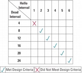
Table 1 shows the efficacy of this code change on the Cisco 7500 Series Router. Prior to the change, twenty-six seconds was the lowest the dead-interval that could be configured and still achieve consistent results. The code changes allowed the dead-interval to be set as low as eight seconds, while still producing the expected results.
Table 1.
Cisco 7500 Series Router-OSPF-~5000 Routes-with Change CSCdz80936 Active
ADDITIONAL TESTING
The E2EST testing restricted itself to 3 seconds as a lower limit on setting the HOLD-TIME timer. This seems to be a reasonable limit, because there are some significant downsides to setting the HOLD-TIME too low. (See Caveats section of this document)
Still, the question "What is the absolute minimum to which the hold-time can be set, and still have Cisco NSF work as expected?" may arise.
To answer this question it is necessary to know a bit about how Cisco Stateful Switchover (SSO) operates. First, it is important to distinguish the operation of Cisco SSO from Cisco NSF.
Cisco SSO refers to a variety of internal software modifications to Cisco routers that allow them to share state information between redundant route processors. Some constituent parts of SSO include the protocols used to pass information between route processors, the ways in which redundancy events are signaled and the manner in which Layer 2 connections are maintained after switchover.
Conversely, Cisco NSF refers to the modifications made to Cisco Express Forwarding and various supported routing protocols. These modifications enable a router to continue forwarding and reconverge with routing peers during the process of route processor switchover.
Cisco NSF and Cisco SSO work together, and rely upon each other to provide a complete High Availability solution. Thus, while the ability to send a protocol HELLO very rapidly after switchover is a Cisco NSF function, it relies heavily on Cisco SSO.
As there is some processing overhead involved in performing a switchover, OSPF or ISIS HELLOs are delayed until the completion of that processing activity. The switchover activity takes some non-zero amount of time to complete, and must be factored into all calculations.
Example 1 illustrates the relative times that these functions require during a switchover process on an NSF Capable router.
Example 1
Route Processor NSF Switchover
*May 12 06:36:24.687: %REDUNDANCY-3-SWITCHOVER: RP switchover (PEER_REDUNDANCY_)
*May 12 06:36:26.703: OSPF: Interface GigabitEthernet3/0/0 going Up
*May 12 06:36:26.703: OSPF: Send hello to 224.0.0.5 area 0 on GigabitEthernet3/0
*May 12 06:36:26.707: OSPF: Rcv hello from 1.1.1.5 area 0 from GigabitEthernet35
*May 12 06:36:26.707: OSPF: 2 Way Communication to 1.1.1.5 on GigabitEthernet3/Y
*May 12 06:36:26.707: OSPF: NSF 2 Way Communication to 1.1.1.5 on GigabitEthernL
*May 12 06:36:26.707: OSPF: End of hello processing
As we can see from the highlighted lines, the switchover begins at 06:36:24.687, and the first HELLO after switchover is sent at 06:36:26.703. This provides us with a gap of 2.016 seconds from the time of switchover until the first HELLO is sent.
Based on this methodology, the same tests were performed on the Cisco 12000 and 10000 routers. The 7500 was not included in these tests since we already concluded that the minimum recommended value for neighbor hold-time or dead-interval when that hardware is operating in SSO mode is 6 to 8 seconds. The results for the 12000 and 10000 series routers are presented in Table 2.
Table 2. Time to First HELLO
ISIS (IETF)
ISIS (Cisco)
OSPF
Cisco 10000
2.020
2.016
2.016
Cisco 12000
2.200
2.292
2.276
Assuming a HELLO timer set at 1 second, it takes slightly more than 2 seconds to send out the first IGP protocol HELLO packet. Therefore, do not set the dead-interval or the hello-multiplier any lower than this or traffic forwarding will not be preserved.
While this testing does provide good insight into the internal processes on the router performing the switchover, it does not capture the complete picture of the adjacency maintenance. Because the last HELLO to the peer prior to the switchover could have been at any time between 0-1 seconds prior to switchover, the hold-timer on the neighbor router was already running at the time of switchover. Therefore, it is equally important to examine the switchover from the neighbor router's point of view.
In Example 2, the highlighted lines indicate the last HELLO packet prior to switchover and the first HELLO packet after switchover. Subtracting one time from the other we see a gap of 2.376 seconds (~2.4 seconds).
Example 2
Neighbor Router View of Switchover
*Jul 21 14:34:55.211: OSPF: Rcv hello from 100.1.1.3 area 1 from POS0/1/0 172.16.6.3
*Jul 21 14:34:55.211: OSPF: End of hello processing
*Jul 21 14:34:55.431: OSPF: Send hello to 224.0.0.5 area 1 on POS0/1/0 from 172.16.6.5
*Jul 21 14:34:56.431: OSPF: Send hello to 224.0.0.5 area 1 on POS0/1/0 from 172.16.6.5
*Jul 21 14:34:57.431: OSPF: Send hello to 224.0.0.5 area 1 on POS0/1/0 from 172.16.6.5
*Jul 21 14:34:57.587: OSPF: Rcv hello from 100.1.1.3 area 1 from POS0/1/0 172.16.6.3
*Jul 21 14:34:57.587: OSPF: Send hello to 172.16.6.3 area 1 on POS0/1/0 from 172.16.6.5
*Jul 21 14:34:57.587: OSPF: End of NSF hello processing
The same tests were performed on the Cisco 10000 and 12000 Series Internet Routers with this methodology, and the results are presented in Table 3.
Table 3. Neighbor View of Route Processor Switchover
ISIS (IETF)
ISIS (Cisco)
OSPF
Cisco 10000
2.088
2.420
2.604
Cisco 12000
2.948
2.560
2.376
Table 3 should not be interpreted as differentiating between the tested hardware or its ability to send a speedy HELLO packet shortly after switchover. In fact, both of the hardware products tested performed similarly in terms of completing the Cisco SSO internal processes. The variations in the table can be attributed to the point at which we perform the switchover-relative to the neighbors (already-running) hold timer.
The neighbor router's hold-timer is already active at the point at which the switchover occurs, so there will be an additional 0-1 seconds added to the minimum time required to switchover and send the first HELLO packet.
The results show that both hardware products performed under the 3-second mark in all variations, and the margin-for-error is very small. Any latency increase within the router or across the media could easily push the gap above 3 seconds.
Although it can be shown that the minimum setting for the hold-time timer is about 3 seconds, a practical, conservative setting of four or more seconds is the minimum recommended for deployment.
OTHER CONSIDERATIONS
In order to obtain the results in this document, some other minor configuration tweaking was necessary to provide the fastest possible switchover. When examining the progress of the internal Cisco SSO process, it became apparent that the transition to the UP state on the interfaces of the NSF-capable router was not occurring as quickly as it could. This was adding an extra 1-2 seconds to the entire switchover. By enabling the command "carrier-delay msec 0" on the interfaces of the routers, this delay was eliminated.
Setting "carrier-delay msec 0" effectively turns off any delay in the "UP/DOWN" transitions to interfaces. Customers who do change the "carrier-delay" parameter are also advised to implement the Cisco IP Event Dampening functionality, to more easily detect and react to rapidly flapping links. IP Event Dampening is documented at:
The other consideration involves the manner in which Cisco SSO signals switchover events between its redundant route processors. Under most circumstances, the need to perform a switchover is actively signaled by the system. Thus, the switchover detection time is effectively zero. Most hardware or software failures that may occur should be internally signaled.
In rare cases, the system has a more difficult time determining that a switchover is necessary. As a failsafe mechanism, Cisco SSO relies on a keep-alive procedure between the redundant route processors in the system. Keep-alive packets are transmitted using Inter-process Communication (IPC). By default, if keep-alive packets are missed for 3 seconds, switchover is initiated because it is reasonable to assume that something is wrong with the system.
At this point, the network designer has three alternatives:
1. Raise the IGP hold-timers to seven seconds to accommodate all failure scenarios. Setting the timer to this value would account for the situation in which the route processor has to be detected via IPC keep-alive failure (3 seconds) plus the safe value for post-switchover behavior (4 seconds for the Cisco 10000 and 12000 Series Internet Routers).
2. Leave the IGP hold-timers at 4 seconds. This will allow Cisco NSF with SSO to operate as expected in the majority of failure scenarios. In the exception cases, where the route processor needs to use IPC keep-alive to determine the need to switchover to the redundant route processor, the traffic will failover to a redundant path on a different system. Remember, the keep-alive procedure is a "failsafe" mechanism while the internal switchover signaling procedures are expected to cover most failures.
3. Lower the IPC keep-alive timer. This can be achieved with the command "redundancy/main-cpu/switchover timeout <milliseconds>". By default, this timer is set for 3 seconds, and can be lowered with the preceding command. It should be strongly emphasized that there is an element of risk to lowering this timer. If the standby route processor does not hear from the active route processor within the timeout period, an route processor switchover will be initiated. Thus, if this timer is set to a very low value, there is the danger of false alarms-causing an route processor switchover when one is not required. In addition, there will be increased CPU and IPC bandwidth usage associated with setting this timer to a very low value.
As different customers will have different availability requirements, Cisco cannot provide a specific recommendation amongst these options.
CAVEATS
CPU And Other Considerations
Although it is a fairly common practice to lower the HELLO and HOLD-TIME timers on OSPF or ISIS within certain environments, it is important to exercise caution when manipulating these timers. While the obvious benefit of timer manipulation is faster convergence, this approach also has its drawbacks, including:
• Increased CPU and bandwidth usage, if the router has a large number of interfaces. The extra CPU and bandwidth should be negligible in smaller networks.
• Increased risk of "false alarms", a condition that occurs when the timers have been set low enough that any unusual network condition can cause them to expire, leading to unintended reconvergence. An example of this would be a transient broadcast storm that might cause the loss of protocol HELLOs.
The protocol timers on a production network should only be changed after significant testing in a lab environment that simulates the scaling and traffic flow patterns of the target deployment.
HARDWARE DEPENDENCIES
As the testing demonstrates, certain hardware dependencies affect how low the OSPF and ISIS timers can be tuned. As future hardware products adopt the Cisco NSF technology, they too will have their own implementation-specific results. Please reference the test results for each specific hardware product in question and refrain from extrapolating performance results to other hardware products.
EIGRP TESTING
The ESE lab conducted some testing, similar to the tests described previously, of the effects and relationship between the manipulation of EIGRP Hello and Hold-time and NSF/SSO.
The tests concluded that the minimum safe Hello and Hold-time settings recommended are 2 and 6 seconds respectively. With this being the case, the network designer must make a decision whether the increased transmission failure detection time is more significant than the potential benefit from relief of Supervisor hardware or software failures. An objective decision can only be made by comparing the probabilities of the various failure causes for the specific network in question.
CONCLUSION
Based on these initial tests, Cisco can make preliminary deployment recommendations about the interoperation between Cisco NSF and ISIS/OSPF timer manipulation.
For ISIS, it seems that these two technologies interoperate quite well. In nearly all test cases, the interaction between the technologies produced the expected results. The only direct caveat to arise from the testing was the hardware-specific requirement for the Cisco 7500 Series Router. When using this hardware as an NSF-capable router, the combination of hello-interval and hello-multiplier must exceed six seconds. Again, based on earlier Cisco NSF testing, this result is not unexpected.
For OSPF, the current implementation in Cisco IOS Software Release 12.0(22)S is structured to require a 26-second dead-interval timer to provide consistent results. Realistically, a 26-second dead-interval timer is not much better than the default interval of forty seconds.
Customers who need to deploy Cisco NSF for OSPF in conjunction with timer manipulation are advised to deploy versions of code that implement the fix found in Cisco IOS Software Releases 12.0(25)S and 12.2(15)T1.
For campus networks where EIGRP is deployed, and timer manipulation is desired for fast convergence, careful examination of historical failures and their probability of recurrence is suggested before making a decision where and when timers should be altered, and NSF/SSO deployed.
However, the test results presented here should not be misconstrued as an official Cisco endorsement of the practice of lowering IGP hold-time timers. As mentioned in the "Caveats" section of this document, there are some risks associated with doing so. Ultimately, the customer-in consultation with their Cisco system engineer or Cisco TAC-must determine if the benefits of lowered IGP timers outweigh the risks.
These tests do provide a foundation for making informed decisions when considering the concurrent deployment of Cisco NSF and ISIS/OSPF timer manipulation.
ACKNOWLEDGEMENTS
Many thanks to David Millsom (dmillsom@cisco.com), Ahamed Basheer (abasheer@cisco.com), Nga Trinh Vu (nvu@cisco.com), and engineers from ESE lab for taking time out of their busy testing schedule to perform some of these tests.
[an error occurred while processing this directive]