Introduction
1.1 Packet Capture, NetFlow, and IP SLA
1.2 IP SLA Components
1.3 IP SLA Operation Support Release
2.0 IP SLA Operation Functional Areas
2.0.1 Availability Monitoring
2.0.2 Network Monitoring
2.0.3 Application Monitoring
2.0.4 Voice Monitoring
2.0.5 Video Monitoring
3.0 Architecture and Deployment
3.0.1 Design
3.0.2 Accuracy
4.0 IP SLA Sample Configurations
4.0.1 UDP Jitter Operation
4.0.2 TCP Operation (HTTP)
4.0.3 Voice Monitoring with Different Operations
4.0.4 Video Monitoring with UDP Jitter
4.0.5 QoS SLA Monitoring
5.0 References
6.0 Acronyms
Introduction
A Service Level Agreement (SLA) is a formal negotiated agreement between two parties specifying the characteristics of a service. It is a contract that exists between customers and their service provider, or between service providers. It records the common understanding about services, priorities, responsibilities, guarantee, etc. with the main purpose to agree on the level of service. For example, it may specify the levels of availability, serviceability, performance, operation or other attributes of the service like billing and even performance incentives and/or penalties when certain service level thresholds are crossed.
IP SLA is an embedded agent in Cisco IOS® Software designed to measure and monitor common network performance metrics like jitter, latency (delay), and packet loss. IP SLA has evolved with advanced measurement features like application performance, Multiprotocol Label Switching (MPLS) awareness, and enhanced voice measurements. It can be used throughout the SLA lifecycle as a tool to quantify the network performance in different stages to take both reactive and proactive approach in meeting the SLA requirements
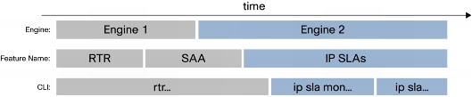
IP SLA was introduced originally as Response Time Reporter (RTR) in Cisco IOS Software 11.2. RTR was renamed Service Assurance Agent (SAA) in 12.0(5)T. Version 12.3(14)T introduced the more aptly named term, IP SLA. All the corresponding command-line interface (CLI) operations now reflect this name in both show and configuration commands. During the name change, the core IP SLA code in Cisco IOS Software also changed from the older code, known as IP SLA Engine 1, into the newer code, known as IP SLA Engine 2. Figure 1 shows the name transition and the corresponding changes in the Cisco IOS Software CLI to reflect it.
Figure 1. Name Changes
1.1 Packet Capture, NetFlow, and IP SLA
IP SLA operations are sometime referred to as probes, not to be confused with hardware or software packet-capture applications like tcpdump or ethereal or hardware-based sniffers, which are also referred to as probes. Packet capture works in a promiscuous mode; that is, packet-capture applications actively listen and capture packets in the wire. NetFlow is a Cisco® technology that allows Cisco devices to send packet flows to a NetFlow collector application. Both packet capture and NetFlow collectors are passive probes; they capture the actual network traffic flows to base their analysis. IP SLA operations are based on active probes; synthetic network traffic is generated strictly for the purpose of measuring a network performance characteristic of the defined operation. By using an active probe mechanism with synthetic network traffic, IP SLA has greater flexibility:
• It has visibility of the processing time on the device versus transit or on-the-wire time and, therefore, can give a more granular and accurate measurement.
• It can differentiate among different measurements, for example, User Datagram Protocol (UDP) versus Internet Control Message Protocol (ICMP) or TCP statistics, so the measurement specifically reflects the current operation and not a generalized overview of the entire traffic.
• IP SLA can be used as a proactive tool since it allows traffic to be created in a controlled environment using different protocols and ports. This allows greater flexibility in terms of simulating future growth with expected traffic patterns or creating a baseline with existing benchmarks.
Because of their distinct areas of operation and architecture, IP SLA and NetFlow technologies complement each other; IP SLA is more suited for performance measurement, whereas NetFlow is more geared toward accounting. Some other advantages of using IP SLA are:
• Near millisecond precision
• Proactive notification using Simple Network Management Protocol (SNMP) traps based on a defined threshold or trigger of another IP SLA operation
• Historical data storage
• Comprehensive hardware support makes this a very cost-scalable solution because it does not require dedicated probes
1.2 IP SLA Components
IP SLA has two main components (Figure 2):
Figure 2. Components of IP SLA
• Source
This Source is where IP SLA operations are defined. Based on the configuration parameters, the source generates packets specific to the defined IP SLA operations and analyzes the results and records it so that it can be accessed through CLI or SNMP. A source router can be any Cisco router that can support the IP SLA operation being configured.
• Target
The IP SLA target depends upon the type of IP SLA operation defined. For FTP/HTTP operations, the target would be an FTP/HTTP server. For Routing Table Protocol (RTP) and UDP jitter (voice over IP [VoIP]), the target must be a Cisco device with the responder feature enabled, since both the source and target participate in the performance measurement. The IP SLA responder has an added benefit of accuracy because it inserts in/out time-stamps in the packet payload and therefore measures the CPU time spent. The IP SLA responder can be enabled with the configuration command:
ip sla responder
1.3 IP SLA Operation Support Release
Table 1 maps IP SLA operations with each supported Cisco IOS Software version.
Table 1. IP SLA Operations and Cisco IOS Software Versions
Feature
Release
11.2
12.0(3)T
12.0(5)T
12.0(8)S
12.1(1)T
12.2
12.2(2)T
12.2(11)T
(Engine2)
12.3(4)T
12.3(12)T
12.4(4)T
ICMP Echo
●
●
●
●
●
●
●
●
●
ICMP Echo Path
●
●
●
●
●
●
●
●
●
UDP Echo
●
●
●
●
●
●
●
●
TCP Connect
●
●
●
●
●
●
●
●
UDP Jitter
●
●
●
●
●
●
●
HTTP
●
●
●
●
●
●
●
DNS
●
●
●
●
●
●
●
DHCP
●
●
●
●
●
●
●
DLSW+
●
●
●
●
●
●
●
SNMP Support
●
●
●
●
●
●
●
UDP Jitter With
One Way Latency
●
●
●
●
●
●
FTP Get
●
●
●
●
●
●
MPLS/VPN Aware
●
●
●
●
●
Frame-Relay (CLI)
●
●
●
●
●
ICMP Path Jitter
●
●
●
●
●
APM
●
●
●
●
●
Voice with MOS/ICPIF Score
●
●
●
Post Dial Delay H323/SIP
●
●
Voice with RTP
●
The various IP SLA operations can also be classified as follows:
• ICMP-based operations for echo, path echo, and path jitter
• UDP-based operations, such as echo, jitter, Domain Name Service (DNS), and Dynamic Host Configuration Protocol (DHCP)
• TCP-based operations, such as TCP connect, FTP, HTTP, and DLSw+
• Layer 2 operations, such as Frame Relay, ATM, and MPLS
• VoIP-related operations, such as VoIP jitter, VoIP gatekeeper registration delay monitoring and VoIP call setup (postdial delay) monitoring. The new RTP-based VoIP operation was introduced in Cisco IOS Software Release 12.4(4)T.
2.0 IP SLA Operation Functional Areas
IP SLA operations can be broadly categorized into the functional areas availability monitoring, network monitoring, application monitoring, voice monitoring, and video monitoring.
2.0.1 Availability Monitoring
ICMP Echo
ICMP echo measures the end-to-end response time between a Cisco router and any IP device by measuring the time between sending an ICMP echo request message to the destination and receiving an ICMP echo reply. This operation takes into account the processing time taken by the sender but cannot take into account any processing time in the target device. This is a good tool to measure availability but does not give much indication if there are any underlying problems in the network or destination host.
ICMP Path Echo
The path discovered ICMP echo operation is different from the regular ICMP echo in that it first does a traceroute to discover the path from a source to the destination and then measures the response time between the source router and each of the intermittent hops in the path. It also has an option of using strict and loose source routing (LSR), which enables IP SLA to use a particular path instead of using traceroute's discovered path. This operation gives more detail on the IP addresses of the hops taken as well as any failures in the intermediate path.
ICMP Jitter
The ICMP jitter operation is very similar to ICMP echo but also provides latency, jitter, and packet loss beside the round-trip measurement. Jitter, also known as IP Packet Delay Variation (IPDV), is a measurement of delay variation. For example, if five packets are sent with an interval of 5 ms each, they should be received 5 ms apart at the destination. If a certain packet arrives after 7 ms, the jitter value is a positive number 2 (7 - 5); if it is received in 3 ms, the value is a negative jitter of -2 (3 - 5). For applications like VoIP and video, a jitter value of 0 is the most ideal.
ICMP Path Jitter
The path discovered ICMP jitter operation is very similar to ICMP path echo but also provides jitter operation statistics like latency, jitter, and packet loss on a per hop basis. The operation first discovers the path using traceroute, then it sends an ICMP echo message to determine the response time, jitter, and packet loss for each of the hops.
UDP Echo
The UDP echo operation is more useful than ICMP echo because the IP SLA responder understands UDP echo and therefore the operation accounts for the processing time taken by the target to generate a more accurate measurement.
UDP Jitter
The IP SLA UDP jitter operation was primarily designed to diagnose network suitability for traffic applications such as VoIP, video over IP, or real-time conferencing. This is the only operation that supports microsecond (10-6 second) precision, which makes it ideal for monitoring voice, video, and other highly sensitive applications. One-way jitter accuracy depends on clock synchronization between the source and destination. The UDP jitter operation requires an IP SLA responder in the destination, and using Network Time Protocol (NTP) or Global Positioning System (GPS) as a time protocol is recommended for accuracy. The IP SLA UDP jitter packets generated have sequencing information as well as time-stamps for both the sending and receiving sides. With that information, UDP jitter operations are capable of measuring the following:
• Per direction jitter (source to destination and destination to source)
• Per direction packet loss
• Per direction delay (one-way delay)
• Round-trip delay (average round-trip time)
• Out of sequence and corrupted packets
2.0.2 Network Monitoring
DLSw+
The DLSw+ operation measures the Data Link Switching Plus (DLSw+) protocol stack and network response time between DLSw+ peers. This operation reports Round-Trip Time (RTT) as well as error statistics, failed operations, sequence error, and so on.
MPLS VPN
IP SLA responder and IP SLA operations have been enhanced to work within an MPLS network by specifying Virtual Route Forwarding (VRF) routing tables for forwarding. Designed to monitor MPLS health, these operations work on MPLS Layer 3 under the IP layer and discover MPLS issues even when IP routing is working fine. Using VRF tables allows IP SLA packets to be sent from one Provider Edge (PE) to another PE using the specified VPN. The following IP SLA operations can be used to measure response time of a MPLS VPN:
• ICMP echo
• ICMP path echo
• ICMP path jitter
• UDP echo
• UDP jitter
Frame Relay
The IP SLA Frame Relay monitoring operation allows monitoring of physical links of Frame Relay connections. Besides round-trip time, the operation also provides the total number of frames transmitted from the source to the destination and vice versa, throughput, packet loss, and many more Frame Relay-specific statistics. An IP SLA responder for Frame Relay in the destination is required for this operation. It can be enabled with the configuration command:
ip sla responder frame-relay [all/interfaces]
ATM
The IP SLA ATM monitoring operation is very similar to the IP SLA Frame Relay operation. Besides round-trip, it reports ATM-specific counters. The configuration for ATM monitoring is unique in that you configure the same operation on both the source and destination for this operation, and an IP SLA responder is not required. Also, ATM operation is supported in a limited number of devices: 2600/3660 with E1/T1 interfaces, 7200, and MC 3810s.
2.0.3 Application Monitoring
TCP Connect
The IP SLA TCP connect operation can be used for general availability monitoring but is more useful to monitor server response time on servers running specific TCP-based applications. A typical TCP connect operation would be to monitor a database server running MS SQL server on TCP port 1433 or mySQL server on TCP port 3306. If the destination is not a Cisco router, make sure to disable the IP SLA control protocol or the operation may fail. IP SLA uses the control protocol to communicate with an IP SLA responder, in this case, to enable the target port.
HTTP
The HTTP operation measures HTTP server responsiveness by measuring response time between the source and HTTP server to retrieve a Web page. The HTTP response time is a sum of three individual round-trip time measurements:
• DNS lookup
• TCP connect
• HTTP transaction time
HTTP transaction time measures the RTT to request and get a response from an HTTP server. This operation gives individual RTTs for all the three operations separately besides other statistics in error, connection timeout, and so on. Only an HTML page is retrieved by the operation; no image is downloaded. Both HTTP GET and raw requests that support authentication are supported by the HTTP operation.
FTP
The FTP operation measures round-trip time between a source device and an FTP server to download a file. This operation can be used to measure network capacity by downloading large files. By default, passive FTP is used, but active mode can also be enabled.
DHCP
The DHCP operation measures the round trip between a source and a DHCP server to obtain a leased IP address. When a specific DHCP server is configured with the interface command "ip helper-address", the DHCP operation sends a directed DHCP request to the DHCP server using DHCPREQUEST packets. If no DHCP server is defined, this operation sends a broadcast traffic using DHCPDISCOVER packets to every IP interface in the device. DHCP operation also works with DHCP relay agent, a device that is normally used to forward DHCP packets between a DHCP client and a server when they are not both in the same subnet.
DNS
The DNS operation measures the round-trip time a name lookup request takes from a source to a DNS server. An efficient DNS lookup plays an important role in an IP network where delay in name lookup can cause latency in applications.
2.0.4 Voice Monitoring
VoIP UDP Jitter
The IP SLA VoIP UDP jitter operation can simulate voice traffic by using common codecs and UDP traffic that are similar to real VoIP traffic. The VoIP UDP jitter operation can return two additional numerical values that will rate the voice quality:
• MOS (mean opinion score): The quality of transmitted speech is a subjective response of the listener. Each codec used for transmission of VOIP provides a certain level of quality. A common benchmark used to determine the quality of sound produced by specific codecs is MOS. With MOS, a wide range of listeners have judged the quality of voice samples sent using particular codecs on a scale of 1 (poor quality) to 5 (excellent quality). The opinion scores are averaged to provide the mean for each sample. The 1998 ITU-G.107 E-model calculation is the basis for how the MOS is calculated.
• ICPIF (the calculated planning impairment factor) is a measurement that tries to quantify, for comparison and planning purpose, the key impairments to voice quality that are encountered in the network. The ICPIF value is mathematically derived by adding various impairments like loudness, distortion, echo, jitter, and so on and is represented in a numerical value that typically ranges from 5 (very low impairment) to 55 (very high impairment). ICPIF values numerically less than 20 are generally considered "adequate."
The addition of these two voice metrics greatly enhances the scope of a UDP jitter operation by giving an estimation of the voice quality. VoIP UDP jitter supported codecs:
• G.711 A Law (g711alaw: 64 kbps PCM compression method)
• G.711 mu Law (g711ulaw: 64 kbps PCM compression method)
The VoIP UDP jitter operation uses UDP traffic to generate approximate VoIP scores. All of these existing measurements operate at the IP level; therefore it is difficult to simulate an actual voice quality that is in effect. RTP operation overcomes this shortcoming by using the same transport protocol as VoIP calls, sending an actual RTP stream generated by software. In the receiving side, it is decoded by a real digital signal processor (DSP) hardware, which also measures jitter and drop metrics. This operation can measure jitter at source and destination, R-factor at source and destination, MOS-CQ (mean opinion score-conversation quality), and packet sequence.
VOIP Call Setup (Postdial Delay Monitoring)
The IP SLA VoIP call setup monitoring feature provides the ability to measure your network's response time for setting up a VoIP call. The IP SLA source router must also support the IP SLA VoIP test-call application to enable the VoIP call setup operation. You can determine whether the test-call application is supported by using the following command in EXEC mode:
show call application voice
With the IP SLA VoIP test-call application enabled, H.323 or Session Initiation Protocol (SIP) call messages can be sent to and received by the originating and terminating gateways. The configuration for the IP SLA VoIP call setup operation is essentially the same for both protocols. If a gatekeeper or directory gatekeeper is involved in the H.323 call signaling, additional messages are sent and received between the originating and terminating gateways before the call message (containing a call number) is actually sent. The operation also measures any extra time taken by the use of a gatekeeper or directory gatekeeper involved in H.323 call signaling.
If a proxy server or a redirection server is used, IP SLA VoIP call setup also measures any additional time required for the message sent/received.
VOIP Gatekeeper Registration Delay Operation
The IP SLA VoIP gatekeeper registration delay operation provides statistical data on the amount of time taken to register a gateway to a gatekeeper.
2.0.5 Video Monitoring
IP SLA currently does not have any operation designed specifically to monitor video traffic. UDP jitter can be used to simulate some video traffic.
3.0 Architecture and Deployment
IP SLA design depends upon the primary goal of the deployment. Possible goals could be to monitor network health, increase uptime, or to deploy and monitor an application. Some of the key aspects that influence the design are performance metrics, IP SLA operations, hardware and software choices, and network management applications.
IP SLA collects the following performance metrics:
• Delay (both round-trip and one-way)
• Jitter (one-way)
• Packet loss (one-way)
• Packet sequencing (packet ordering)
• Packet corruption detection
• Path (per hop)
• Connectivity (one-way)
• FTP server or HTTP Website download time
• Voice quality scores (MOS, ICPIF)
Selecting IP SLA operation depends on the monitoring requirement and metrics, given in Table 2.
Table 2. Monitoring Requirements and Metrics for IP SLA Operations
Data Traffic
Reachability
Service-Level Management
VoIP
Streaming Video
Requirements
• Minimize delay, packet loss
• Verify quality of service (QoS)
• Connectivity testing
• Application testing
• Measure delay, packet loss, jitter
• One-way
• Minimize delay, packet loss, jitter
• Minimize delay, packet loss
IP SLA Metrics
• Jitter
• Packet loss
• Latency
• per QoS
• Connectivity tests to IP devices
• Connectivity tests to network services
• Network connectivity
• Jitter
• Packet loss
• Latency
• One-way
• Enhanced accuracy
• NTP
• Jitter
• Packet loss
• Latency
• MOS, ICPIF Voice quality score
• Jitter
• Packet loss
• Latency
IP SLA Operation
• Jitter
• Echo
• TCP
• FTP, HTTP
• DNS, DHCP
• DLSW+, MPLS, ATM, Frame Relay
• UDP jitter
• VoIP UDP jitter
• VoIP RTP
• VoIP call setup
• VoIP gatekeeper
• UDP jitter
Table 3 lists the recommended Cisco performance threshold. These thresholds may vary according to the business need.
Table 3. Recommended Performance Threshold
Traffic Type
Maximum Packet Loss
Maximum One-way Delay
Maximum Jitter
VoIP
1%
120 ms
30 ms
Video Conferencing
1%
150 ms
50 ms
Streaming Video
2%
5 s
N/A
3.0.1 Design
IP SLA can be implemented in any Cisco IOS Software device that supports the operation. The deployment can be done in three different ways, full mesh, partial mesh, and composite SLAs. The selection depends on the measurement requirement, operation, and scalability.
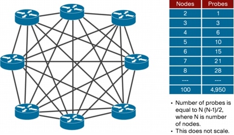
3.0.1.1 Full Mesh
A network in which devices are organized in a mesh topology (Figure 3), and either a physical circuit or a virtual circuit connects each network node to every other network node. A full mesh provides substantial redundancy, but because it can be prohibitively expensive to implement, it is usually only used in network backbones.
Figure 3. Full-Mesh Design
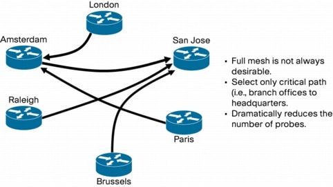
3.0.1.2 Partial Mesh
The partial-mesh design (Figure 4) is more ideal for most scenarios. It can be designed to select only critical paths (for example, branch offices to headquarters, strategically critical devices). The number of IP SPA operations that needs to be configured is dramatically reduced with this design.
Figure 4. Partial-Mesh Design
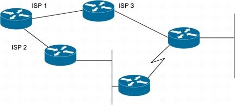
3.0.1.3 Composite SLAs
The Composite SLAs design (Figure 5) can be used only to measure delay. Individual delay measurements along the path are added to get a composite number that gives the total delay.
Figure 5. Composite SLAs Design
This design is ideal when a network traverses multiple domains or ISPs, where it may be difficult to configure an IP SLA operation using any other design. However, this kind of design has some restrictions:
• Measurements are less accurate, as each measurement carries its own error tolerance (typically ±1 ms per measurement).
• This method cannot be used to measure jitter and MOS because jitter measurements cannot be added as composites because of factors such as positive jitter, negative jitter, and average jitter values.
IP SLA design best practices recommend using a dedicated device to poll the others to increase manageability.
3.0.2 Accuracy
Implementing some of the IP SLA features and design can help improve the accuracy of IP SLA measurements. Following are some of the implementations that should be considered -
3.0.2.1 IP SLA Responder
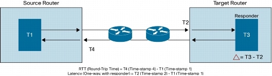
Cisco IOS IP SLA Responder is a Cisco IOS Software component whose functionality is to respond to Cisco IOS IP SLA request packets. The IP SLA source sends control packets before the operation starts to establish a connection to the responder. Once the control packet is acknowledged, test packets are sent to the responder. The responder inserts a time-stamp when it receives a packet and factors out the destination processing time and adds time-stamps to the sent packets. This feature allows the calculation of unidirectional packet loss, latency, and jitter measurements with the kind of accuracy that is not possible with ping or other dedicated probe testing (Figure 6).
Figure 6. The IP SLA Responder
Responder is supported in UDP jitter, UDP echo, and TCP connect operations. MPLS VRF-aware operations are supported in ICMP echo, ICMP path echo, UDP echo, UDP jitter, and ICMP path jitter operations. Some of the newer Linksys devices also support this feature.
3.0.2.2 Time Synchronization
The system clock accuracy also affects the accuracy of the resulting metrics. It is essential for IP SLA operations like one-way latency (delay) to have precise time synchronization. Some of the other operations, also round-trip and interarrival time, are less sensitive to clock variations.
3.0.2.3 Shadow Router
A dedicated router used as a source of IP SLA measurement is also called a shadow router. Implementing IP SLA with a shadow router has several advantages:
• Dedicated router would offset the resource load on production router from the implemented IP SLA Network Management operations
• Dedicated router would be a central device that can be independently managed without any impact on network traffic.
• Granting SNMP read-write access to the device might not be such a huge security risk compared to enabling SNMP read-write on a production router carrying customer traffic.
• Better estimation of Layer 2 switching performance can be obtained if the access port is placed on the same switch/linecard as the endpoint to be managed. This is because the IP SLA packets also have to traverse the same interface queuing at the access layer as the regular IP packets.
Common shadow routers used:
• Cisco 2600 and 3700 series
• ISR routers like Cisco 2800/3800 series with DSP are popular for voice monitoring
• Cisco 7200 router with GPS connected to an auxiliary port. The same device can also act as an NTP synchronization point.
Shadow router considerations:
• Transit router should not be used as a shadow router. This is because interrupt level code (interface) competes with IP SLA, and switched traffic takes precedence over local traffic.
• Any device with high forwarding CPU utilization should not be used as a shadow router.
Table 4 shows accuracy prediction and its dependency in device CPU utilization.
Table 4. Accuracy Prediction in CPU Utilization
Device CPU threshold
30 %
60 %
90 %
IPSLA level of accuracy
Great
Good
Impacted
4.0 IP SLA Sample Configurations
Following are some sample configurations for IP SLA operations.
4.0.1 UDP Jitter Operation
Source router:
ip sla 6
udp-jitter 155.155.155.2 11000
ip sla schedule 6 life forever start-time now
Destination Router:
ip sla responder
ipslaProbe#sh ip sla statistics 6
Round Trip Time (RTT) for Index 6
Latest RTT: 40 milliseconds
Latest operation start time: 21:07:04.911 UTC Fri Aug 10 2007
Latest operation return code: OK
RTT Values:
Number Of RTT: 9 RTT Min/Avg/Max: 8/44/97 milliseconds
Latency one-way time:
Number of Latency one-way Samples: 0
Source to Destination Latency one way Min/Avg/Max: 0/0/0 milliseconds
Destination to Source Latency one way Min/Avg/Max: 0/0/0 milliseconds
Jitter Time:
Number of Jitter Samples: 7
Source to Destination Jitter Min/Avg/Max: 4/41/185 milliseconds
Destination to Source Jitter Min/Avg/Max: 1/69/180 milliseconds
Packet Loss Values:
Loss Source to Destination: 0 Loss Destination to Source: 1
Out Of Sequence: 0 Tail Drop: 0 Packet Late Arrival: 0
Voice Score Values:
Calculated Planning Impairment Factor (ICPIF): 0
Mean Opinion Score (MOS): 0
Number of successes: 60
Number of failures: 0
Operation time to live: Forever
4.0.2 TCP Operation (HTTP)
Source router:
ip sla 9
http get http://192.168.100.1/mrtg/192.168.100.2:2.html
ip sla schedule 9 life forever start-time now
ipslaProbe#sh ip sla statistics 9
Round Trip Time (RTT) for Index 9
Latest RTT: 512 milliseconds
Latest operation start time: 20:11:34.794 UTC Fri Aug 10 2007
Latest operation return code: OK
Latest DNS RTT: 0 ms
Latest TCP Connection RTT: 12 ms
Latest HTTP Transaction RTT: 500 ms
Number of successes: 16
Number of failures: 5
Operation time to live: Forever
4.0.3 Voice Monitoring with Different Operations
Example: Simulating G.711 VoIP call with VoIP UDP jitter
Specifications:
• Use RTP/UDP ports 16384 and above; the packet size is 172 bytes (160 bytes of payload + 12 bytes for RTP)
• Packets are sent every 20 milliseconds
• Marked with DSCP value of 8 (ToS equivalent 0x20)
UDP jitter for voice monitoring simulating G.711 VoIP call
ip sla group schedule 1 1-5 schedule-period 1 frequency 15 start-time now
Destination Router:
ip sla responder
4.0.5 QoS SLA Monitoring
IP SLA operations can be marked for type of service (ToS) to match the target class. IP SLA configuration supports only ToS setting; diffserv is not supported. Here is an example of setting multiple IP SLA operation with VoIP UDP jitter marked with a DSCP value of CS3m AF41 and EF (ToS equivalent, 0x60, 0x88, xB8).
UDP jitter for voice monitoring simulating G.729a codec with QoS setting