Fast Failure Detection to Speed Network Convergence
OVERVIEW
In both Enterprise and Service Provider networks, the convergence of business-critical applications onto a common IP infrastructure is becoming more common. Given the criticality of the data, these networks are typically constructed with a high degree of redundancy. While such redundancy is desirable, its effectiveness is dependant upon the ability of individual network devices to quickly detect failures and reroute traffic to an alternate path.
This detection is now typically accomplished via hardware detection mechanisms. However, the signals from these mechanisms are not always conveyed directly to the upper protocol layers. When the hardware mechanisms do not exist (eg: Ethernet) or when the signaling does not reach the upper protocol layers, the protocols must rely on their much slower strategies to detect failures. The detection times in existing protocols are typically greater than one second, and sometimes much longer. For some applications, this is too long to be useful.
Bi-directional Forwarding Detection (BFD) provides rapid failure detection times between forwarding engines, while maintaining low overhead. It also provides a single, standardized method of link/device/protocol failure detection at any protocol layer and over any media.
THE PROBLEM WITH CONVERGENCE
The process of network convergence can be broken up into a set of discreet events*:
• Failure detection: the speed with which a device on the network can detect and react to a failure of one of its own components, or the failure of a component in a routing protocol peer.
• Information dissemination: the speed with which the failure in the previous stage can be communicated to other devices in the network
• Repair: the speed with which all devices on the network-having been notified of the failure-can calculate an alternate path through which data can flow.
An improvement in any one of these stages provides an improvement in overall convergence.
The first of these stages-failure detection-can be the most problematic and inconsistent.
• Different routing protocols use varying methods and timers to detect the loss of a routing adjacency with a peer
• Link-layer failure detection times can vary widely depending on the physical media and the Layer 2 encapsulation used
• Intervening devices (eg: Ethernet switch) can hide link-layer failures from routing protocol peers
Packet over SONET (POS) tends to have the best failure detection time amongst the different Layer 1/2 media choices. It can typically detect and react to media or protocol failures in ~50 milliseconds. This has become the benchmark against which other protocols are measured.
BFD can provide fast failure detection times for all media types, encapsulations, topologies, and routing protocols. In the best-case scenario, it can provide fast failure detection similar to that found in POS.
* The stages of convergence listed here provide a high-level overview of the process. Each stage could be further subdivided into several sub-stages.
A secondary benefit of BFD, in addition to fast failure detection, is that it provides network administrators with a consistent method of detecting failures. Thus, one availability methodology could be used, irrespective of the Interior Gateway Protocol (IGP) or the topology of the target network. This eases network profiling and planning, because reconvergence time should be consistent and predictable.
Common BFD applications include:
• Control plane liveliness detection
• Tunnel endpoint liveliness detection
• A trigger mechanism for IP/MPLS Fast ReRoute
• MPLS Label Switching Protocol date plane failure detection
HOW BFD WORKS*
BFD verifies connectivity between two systems. In the first phase of development, Cisco will support BFD Asynchronous mode, which depends on the transmission of BFD control packets between the two systems.
BFD Packet Formats
The Internet Draft for BFD does not specify a specific encapsulation type for BFD control packets; rather, it recommends the use of an encapsulation "appropriate to the medium and the network". Because the first phase implementation from Cisco will focus on verifying IP connectivity, UDP encapsulation will be used. BFD payload control packets will be encapsulated in UDP packets, using destination port 3784 and a source port in the range of 49152 to 65535**. Even on shared media, like Ethernet, BFD control packets are always sent as unicast packets to the BFD peer.
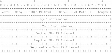
The payload of a BFD Control packet (defined in the BFD Internet Draft) is illustrated in Figure 1, with some additional comments relevant to the Cisco implementation.
Figure 1. BFD Control Packet Payload
* Cisco implementation of BFD is based on an Internet Engineering Task Force (IETF) draft. The complete text of the draft can be found at the IETF BFD Working Group page at http://www.ietf.org/html.charters/bfd-charter.html. Cisco implementation of BFD will be released in phases, with additional functionality and platform support added in each phase. The IETF draft describes some capabilities, which may not be implemented until subsequent phases.
** This conforms to another IETF Draft which specifies how BFD should be used in single-hop IPv4 or IPv6. For more information, see the IETF BFD Working Group page: http://www.ietf.org/html.charters/bfd-charter.html
Field
Description
Vers
The version number of the protocol. The initial protocol version is 0.
Diag
A diagnostic code specifying the local system's reason for the last transition of the session from Up to some other state.
Possible values are:
0-No Diagnostic
1-Control Detection Time Expired
2-Echo Function Failed
3-Neighbor Signaled Session Down
4-Forwarding Plane Reset
5-Path Down
6-Concatenated Path Down
7-Administratively Down
H Bit
The "I Hear You" bit. This bit is set to 0 if the transmitting system either is not receiving BFD packets from the remote system, or is in the process of tearing down the BFD session for some reason. Otherwise, during normal operation, it is set to 1.
D Bit
The "Demand Mode" bit. If set, the transmitting system wishes to operate in Demand Mode*.
P Bit
The Poll bit. If set, the transmitting system requesting verification of connectivity, or of a parameter change.
F Bit
The Final bit. If set, the transmitting system is responding to a received BFD Control packet that had the Poll (P) bit set.
Rsvd
Reserved bits. These bits must be zero on transmit, and ignored on receipt.
Detect Mult
Detect time multiplier. The negotiated transmit interval, multiplied by this value, provides the detection time for the transmitting system in Asynchronous mode.
If the reader is familiar with IGP HELLO protocol mechanisms, this is analogous to the hello-multiplier in IS-IS, which can be used to determine the hold-timer. (hello-interval)* (hello-multiplier) = hold-timer. If a HELLO is not received within the hold-timer, a failure has occurred.
Similarly in BFD - (transmit interval) * (detect multiplier) = detect-timer. If a BFD control packet is not received from the remote system within detect-timer, a failure has occurred.
Length
Length of the BFD Control packet, in bytes.
My Discriminator
A unique, nonzero discriminator value generated by the transmitting system, used to demultiplex multiple BFD sessions between the same pair of systems.
Your Discriminator
The discriminator received from the corresponding remote system. This field reflects back the received value of My Discriminator, or is zero if that value is unknown.
Desired Min TX Interval
This is the minimum interval, in microseconds, that the local system would like to use when transmitting BFD Control packets.
Required Min RX Interval
This is the minimum interval, in microseconds, between received BFD Control packets that this system is capable of supporting.
Required Min Echo RX Interval
This is the minimum interval, in microseconds, between received BFD Echo packets that this system is capable of supporting. If this value is zero, the transmitting system does not support the receipt of BFD Echo packets.
The first phase of the Cisco BFD implementation does not support the use of Echo packets.
* BFD has two different modes: Asynchronous and Demand. In the first phase of BFD development, Cisco will support Asynchronous mode. All subsequent discussion in this section will assume that Asynchronous mode is being used. See the previously referenced Internet Draft for more detail on the differences between these modes.
BFD Initial Session Setup
To better understand how BFD is implemented, consider an example. Imagine two routers, each of which runs EIGRP, connected over a common medium. Both routers have just started up, so no BFD session has been established.
In each router, EIGRP informs the BFD process of the IP address of the neighbor that it needs to monitor. It is important to note that BFD does not discover its peers dynamically. It relies on the configured routing protocols to tell it which IP addresses to use and which peer relationships to form.
BFD on each router will form a BFD control packet. These packets are sent at a minimum of one-second intervals* until a BFD session is established. They may cross in transmission, although BFD is designed to adapt to this condition.
The initial packets from either side will be very similar: Vers, Diag, the H, D, P, and F bits will all be set to zero. My Discriminator will be set to a value which is unique on the transmitting router; Your Discriminator is set to zero, because the BFD session has yet to be established**. The values of the TX and RX timers will be set to the values found in the configuration of the device.
After the remote router receives a BFD control packet during the session initiation phase, it will copy the value of the "My Discriminator" field into its own "Your Discriminator" field and set the H ("I Hear You") bit for any subsequent BFD control packets it transmits. Once both systems see their own Discriminators in each other's control packets, the session is "officially" established. Both systems will continue to send at (at least) one-second intervals until they see the appropriate Discriminators in each other's BFD control packets.
The Discriminator values can also be used to multiplex/demultiplex sessions if there are multiple BFD connections between a pair of BFD peers, or to allow the changing of an IP address on a BFD interface without causing the BFD session to be reset.
Figure 2 illustrates the initial BFD session setup.
* This value is fixed at one second in the first phase. It may be configurable in later phases. It is also worth noting that the Internet draft for BFD defines two modes for session initiation, Active and Passive. An Active node sends BFD control packets in an effort to establish a BFD session. A Passive node does not send any BFD packets until it receives BFD packets from an Active node. In the first phase, Cisco devices implementing BFD will always be Active nodes.
** Although this example is good for illustrative purposes, it is actually rather unlikely-because it requires near-simultaneous transmission of the initial BFD packet by both systems. The more likely occurrence is that one system sends the initial BFD packet, and the receiving system responds back with the "I Hear You" bit set, the "My/Your Discriminator" and other relevant fields populated.
Figure 2. BFD Session Setup
Concurrent with the exchange of control packets to establish the BFD session, BFD timers are also negotiated. The negotiation of the initial BFD timers is somewhat anomalous, because-unlike the subsequent timer changes-it occurs without the exchange of Poll and Final (P and F) bits. The P and F bits are used to ensure that the remote device received the packet requesting the timer change. However, this exchange is not required during initial session setup, as the fact that the remote device changed the value of "Your Discriminator" and set the H bit in subsequent packets is sufficient to ensure that it received the currently requested timer values.
The next section of this document will discuss the details of timer negotiation.
BFD Timer Negotiation
The process of BFD timer negotiation between two BFD devices is a very simple one, and occurs in a few steps. A device needs to assure three things before it can negotiate a BFD timer:
• That its peer device saw the packet containing the local device's proposed timers
• That it never sends BFD control packets faster than the peer is willing to receive them
• That the peer never send BFD control packets faster than the local system is willing to receive them
As mentioned earlier, the setting of "Your Discriminator" and the H bit are sufficient to allow the local device to know that the remote device has seen its packets during initial timer exchange. Once these timers have been negotiated, they can be renegotiated at any time during the session without causing a session reset. The existing timers are maintained during the negotiation period, and the new timers do not take effect until they are acknowledge via a Poll bit and Final bit exchange.
The device that changed its timers will set the P bit on all subsequent BFD control packets, until it receives a BFD control packet with the F bit set from the remote system. This exchange of bits guards against packets that might otherwise be lost in transit. It is extremely important to note that the setting of the F bit by the remote system does not imply that it accepts the newly proposed timers. It merely indicates that the remote system has seen the packets in which the timers were changed.
How, then, are the timers actually negotiated? Each system, upon receiving a BFD control packet will take the "Required Min RX Interval" and compare it to its own "Desired Min TX Interval" and take the greater (slower) of the two values and use it as the transmission rate for its BFD packets. Thus, the slower of the two systems determines the transmission rate.
Because this comparison is performed independently by either peer, it is possible to have asynchronous transmission rates on the link. That is, one peer will be sending BFD control packets more frequently in one direction than the peer is sending in the other direction.
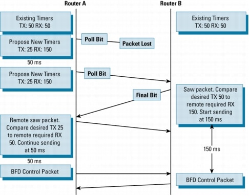
Figure 3 illustrates both Poll/Final bit usage, and timer negotiation:
Figure 3. BFD Timer Negotiation
Figure 3 represents the "worst-case scenario" for BFD because Router A proposes radically different timers than already exist; moreover, it loses a packet when it suggests the change. Here is what occurs during this scenario:
• Router A and Router B both start in a steady state, with agreed upon timers of 50 ms in both directions
• Router A wishes to change its timers to transmit at 25ms and receive at 150 ms. It sends a BFD control packet with the P bit set. Unfortunately this packet is lost in transit.
• Router B would have continued to send BFD control packets at 50ms intervals during this exchange. This is not illustrated in Figure 3.
• After another 50 ms, Router A resends its request to change the timers. Again it sets the Poll Bit. Remember, because the new timers are not in effect yet, Router A must continue to honor the existing timers. The retransmission thus occurs at the 50ms interval.
• Router B sees the packet this time and compares the requested RX interval to its own TX interval. The requested RX interval is larger, so Router B throttles back to sending BFD control packets at 150ms intervals.
• Router A receives the packet with the F bit set. The remote timers are still set at 50ms and 50ms. It compares the requested RX interval to its own Desired TX interval of 25ms. The requested RX interval is larger, so Router B continues to send at 50ms intervals
• The timer negotiation is complete: Router A sends at 50ms intervals, while Router B sends at 150ms intervals.
While the ability to negotiate timers does provide some configuration flexibility, it is anticipated that initial BFD deployments will use identical timer configurations on BFD peers sharing the same media types. Still, timer negotiation does provide some protection against misconfiguration. Even if one peer sets an absurdly low TX or RX timer, the value will be negotiated upwards by a correctly configured peer.
It is also worth noting that-even though the timers have been negotiated to new values-the actual values in the BFD packets remain at the locally-configured settings. For example, although Router B is transmitting at 150ms, an inspection of Router B's BFD control packet would show its Desired Min TX Interval still set to 50ms. Only an internal timer on the device has changed.
The Detect Multiplier is also communicated in the BFD control packets, but is not negotiated, so it is possible to have different detect-timer values at either side of the BFD session.
BFD Failure Detection
Once the BFD session and appropriate timers have been negotiated, the BFD peers will send BFD control packets to each other at the negotiated interval. As previously mentioned, this assumes BFD Asynchronous mode; BFD Demand mode functions differently. These control packets function as a heartbeat, very similar to an IGP HELLO protocol, except at a more accelerated rate.
As long as each BFD peer receives a BFD control packet within the detect-timer period, the BFD session remains up and any routing protocol associated with BFD maintains its adjacencies. If a BFD peer does not receive a control packet within the detect interval, it informs any clients of that BFD session (i.e. any routing protocols) about the failure. It is up to the routing protocol to determine the appropriate response to that information. The typical response will be to terminate the routing protocol peering session and reconverge, bypassing the failed peer.
The preceding information brings up three important points:
• BFD is a "liveliness" detection protocol, but does not-in itself-determine the correct reaction to a detected failure.
• BFD can be used at any protocol layer. It could, for example, detect Physical or Data Link layers failures, if the existing mechanisms did not provide sufficiently speedy detection. However, in the first phase of Cisco BFD support, all BFD clients, particularly the Layer 3 routing protocols (OSPF, IS-IS, EIGRP, and BGP) are at the Network layer.
• Although a single BFD session could, theoretically support multiple client protocols monitoring the same peer, Cisco devices will use one BFD session per client protocol in the first phase of BFD support. In other words, if a network is running OSPF and BGP across the same link to the same peer, it would have two discreet BFD sessions.
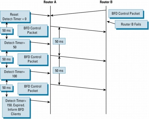
If a BFD device fails to receive a BFD control packet within the detect-timer [(Required Minimum RX Interval) * (Detect Multiplier)], then it informs its client protocol that a failure has occurred. Each time a BFD successfully receives a BFD control packet on a BFD session, the detect-timer for that session is reset to zero. Thus, the failure detection is dependant upon received packets, and is independent of when the receiver last transmitted a packet. This is illustrated in Figure 4:
Figure 4. BFD Failure Scenario
In its next BFD control packet, Router A will set the diagnostic field to a value which indicates why the session was taken down. In this case, the diagnostic will be 1: Control Detection Time Expired. Diagnostics are useful to differentiate between real failures, versus administrative actions. For example, if the network administrator disabled BFD for this session, the diagnostic would be 7: Administratively Down. See BFD Packet Formats above for a list of all possible diagnostics.
CONFIGURING BFD
BFD can be configured in two steps.
The first step in configuring BFD is setting the baseline parameters for all BFD sessions on an interface. The configuration occurs at the interface level and the syntax is as follows:
interval: determines how frequently (in milliseconds) BFD packets will be sent to BFD peers.
min_rx: determines how frequently (in milliseconds) BFD packets will be expected to be received from BFD peers
multiplier: The number of consecutive BFD packets which must be missed from a BFD peer before declaring that peer unavailable, and informing the higher-layer protocols of the failure
Once the baseline parameters have been set, individual protocols must be informed that they will be using BFD for failure detection.
In the first release of BFD, the supported protocols are OSPF, IS-IS, EIGRP and BGP. This document focuses on EIGRP configuration.
There are two different methods to inform EIGRP that it should use BFD for failure detection. BFD can be enabled at the router sub-mode if all EIGRP neighbors have implemented BFD, and it will be universally employed on all interfaces:
!
router eigrp 123
bfd all-interfaces
!
If the user does not wish to enable BFD on all interfaces, it can be enabled on a per-interface basis. This, again, is enabled in router sub-mode.
!
router eigrp 123
bfd interface Gig1/0
!
BFD DEPLOYMENT
Deployment Alternatives
When deploying any protocol or IP functionality, it is appropriate to consider all the alternatives, and be aware of any trade-offs being made. The closest alternative to BFD in conventional EIGRP deployments is use of modified hello and hold timers. By setting EIGRP hello and hold timers to their absolute minimums, the EIGRP protocol to reduce its failure detection mechanism to within the 1-2 second range.
There are several advantages to BFD over the reduced timer mechanism:
• Because BFD is not tied to any particular routing protocol, it can me used as a generic and consistent failure detection mechanism for OSPF, IS-IS, EIGRP, and BGP.
• Because some parts of BFD can be distributed to the data plane, it can be less CPU-intensive than reduced timers, which exist wholly at the control plane.
• Reduced EIGRP timers have an absolute minimum detection timer of 1-2 seconds; BFD can provide sub-second failure detection.
BFD also shares some common caveats with reduced EIGRP timers:
• BFD can potentially generate false alarms-signaling a link failure when one does not exist. Because the timers used for BFD are so tight, a brief interval of data corruption or queue congestion could potentially cause BFD to miss enough control packets to allow the detect-timer to expire. While the transmission of BFD control packets is managed by giving them the highest possible queue priority, little can be done about prioritizing incoming BFD control packets.
• BFD will consume some CPU resources, although many optimizations have been made to ensure the CPU usage is minimal. On non-distributed platforms, in-house testing has shown a minor 2% CPU increase (above baseline) when supporting one hundred concurrent BFD sessions*. On distributed platforms, there is no impact on the main Route Processor CPU, except during BFD session setup and teardown. It is important to note that, because of this accelerated handling of BFD control packets, all output features are bypassed. Users cannot, for example, filter or apply Quality of Service (QoS) to transmitted BFD packets.
* As always, performance numbers will vary depending on configuration and traffic patterns. Customers are advised to do due-diligence lab testing before deploying BFD in a live environment.
Releases, Hardware, and Interfaces
The first release of BFD will be supported on two hardware products that run Cisco IOS® Software Releases 12.0S and 12.2S: the Cisco 7600 Series Router and the Cisco 12000 Series Internet Router. The first release of Cisco IOS-XR Software on the Cisco CRS-1 will also support BFD.
BFD will be supported on the Cisco 7600 Series Router in Release 12.2(18)SXE on the following hardware:
Supervisor:
• Sup720 (PFC3A)
• Sup720-3BXL
10GE Modules:
• WS-X6704-10GE
GE Modules:
• WS-X6816-GBIC
• WS-X6724-SFP
• WS-X6408A-GBIC
Optics:
• 10GE XENPAK (XENPAK-10GB-ER, XENPAK-10GB-LR)
• 10GE DWDM ITU XENPAK (P/N TBD)
• DWDM-GBIC-xx.xx DWDM GBIC
• WS-G548x Standard GBIC
• GLC-xx-xx Cisco SFP
DFC Cards:
• WS-F6700-DFC3A
• WS-F6700-DFC3B
• WS-F6K-DFC3
BFD support for OSPF, ISIS, and EIGRP will be available in the first phase release for the Cisco 7600 Series.
For the Cisco 12000 Series Internet Router, the target release for BFD is Release 12.0(31)S. It will provide BFD support for the OSPF, ISIS and BGP protocols. Because BFD will run in distributed mode on the Cisco 12000 Series, it is important to verify that the appropriate line card is also supported. Release 12.0(31)S targets all OC3/OC12/OC48 Engine 3 Packet Over SONET line cards, as well as all Engine 3 Ethernet Cards and Engine 4+ Ethernet Cards.
BFD for the Cisco access platforms is planned for the first release of 12.4T.
Using BFD as Part of a Network Redundancy Plan
BFD can be an important part of an overall network redundancy plan, including other Cisco innovations like Nonstop Forwarding (NSF) and the Hot Standby Router Protocol (HSRP). BFD should be deployed in those sections of the network where subsecond failure detection is required, but cannot be provided by traditional Layer 2 mechanisms.
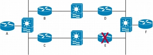
Figure 5 illustrates an example of BFD usage.
Figure 5. BFD Deployment in a Mixed L2/L3 Environment
Even though there is an alternate path available between Routers A and F, a failure on Router E will be hidden from its neighbors (Routers C, D, and F) by the presence of the Layer 2 switches. The switches maintain Layer 2 connectivity for the neighbor routers, which causes them to fall back on using the timers in the Layer 3 HELLO protocol to detect the failure. At the EIGRP default timer settings, this could take up to 15 seconds.
In contrast, if Routers C, D, E, and F were all running BFD, all of Router E's neighbors could detect Router E's failure in less than a second, and immediately begin the reconvergence to the A->B->D->F path.
Although BFD can be used in other deployment scenarios, the L2 switch example is one of the most common and difficult to solve without BFD.
It is worth noting that EIGRP can provide nearly instantaneous convergence through the use of feasible successor routes-which are essentially pre-computed backup routes. However, this solves a different problem from the initial failure detection provided by BFD. So, while EIGRP is the fastest converging of all the IGP protocols, BFD still provides significant value.
BFD Deployment Notes
• Although it may be self-evident, it should be stated that BFD provides its primary benefit in dual-homed environment. Once a failure is detected by BFD, traffic needs an alternate path along which it can flow. Although there is no restriction against using BFD in a singly-homed environment, the benefits are few. It does, however, alert the network administrator more quickly to a problem requiring manual intervention.
If link failures are caused by an intermittent fluctuation at the physical layer initiated by a dirty fiber, loose connector, misbehaving GBIC, or some other cause, BFD will faithfully detect all of these failures. However, it cannot distinguish that a particular link has been bouncing up and down. Cisco IP Event Dampening was intended to mitigate precisely this problem.
• Although some protocols like HSRP and Multicast are not currently BFD-enabled, they can obtain some incremental benefit from BFD deployment. Because these protocols rely on the underlying IGP to determine their reactions to failure, the ability of BFD to help the IGP converge more quickly benefits all upper layer protocols.
• Some care should be used when using BFD in conjunction with other High Availability strategies. Cisco NSF, for example, can provide nearly instantaneous failover between an active and a standby Route Processor in the case of control plane forwarding. However, depending on the platform, there may be enough of a traffic outage during the switchover to cause BFD to prematurely signal a link failure.
• Dual-ring SONET using Automatic Protection Switching (APS) is another deployment scenario where BFD may be inappropriate. SONET with APS should already supply ~50ms switchover protection, and BFD should not be required. The same rule should apply to Spatial Reuse Protocol (SRP) links-either Dynamic Packet Transport (DPT) or Resilient Packet Ring (RPR).
• While all interface types supported in the first phase of Cisco BFD support are high-speed, some care should be taken once BFD becomes more generally available on other platforms with lower-speed links. In particular, the Desired TX Interval and Required Min RX Interval should be set to values appropriate for the link type. While a 50ms heartbeat will be almost unnoticeable on a 10Gbps link, it will have a more significant effect on a 64Kbps link. Performing a PING to the remote BFD peer will estimate the correct timer setting. The timers must be set to at least the measured response time, although a value several orders of magnitude larger would be preferred.
BFD TROUBLESHOOTING
The Cisco BFD implementation offers a wide variety of tools for determining the status of BFD peerings, as well as for debugging the BFD protocol itself.
BFD Status and Debugging
The following commands are implemented to help troubleshoot BFD:
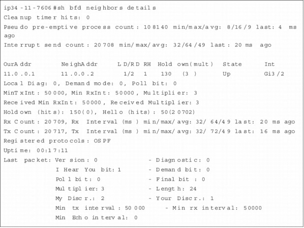
show bfd neighbors [details]
The show bfd neighbors command provides a line-by-line listing of existing BFD adjacencies. If the option details keyword is included, the output will also show BFD protocol parameters and timers per neighbor.
Figure 6. sh bfd neighbors details
The information contained in Figure 6 can be interpreted by inspecting the fields in the BFD Packet Formats section of this document.
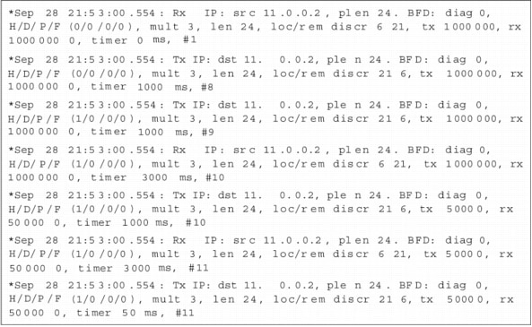
debug bfd packet [neighbor address]
The debug bfd packet command prints debugging information about BFD packets sent and received. The optional [neighbor address] is used to filter output based on neighbor IP address. Because BFD is designed to send and receive packets at a very high rate, some care should be used before enabling this command, especially if there are a large number of BFD peers. It should only be enabled on a live network at the direction of Cisco Technical Assistance Center personnel.
Figure 7. BFD Debugging Output
Figure 7 shows the initial setup of a BFD session. As mentioned before, initial timers are set to 1 second until the session is initialized. Then the timers change to their locally configured values-in this case, 50 milliseconds*.
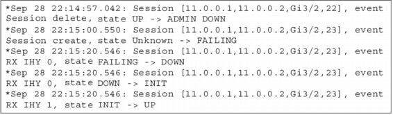
debug bfd event
This command prints debugging information about BFD state transitions. There are four main states for a BFD Session:
• Init: the initial state of a BFD session. No BFD packets have yet been received from the peer of the session.
• Up: a BFD Control packet with the "I Hear You" (IHY) bit set to 1 has been received.
• Failing: a transitional state from the UP state. Either the detection timer is in the process of expiring, or a BFD Control packet with the "I Hear You" bit set to 0 has been received.
• Down: a BFD Control packet with the "I Hear You" bit set to 0 has been received.
As an example of state transition, if a BFD session is in the UP state, and the peer begins sending BFD packets with IHY=0, the state transition is as follows:
UP->FAILING->DOWN->INIT
* Remember that timers are configured in milliseconds, but their values are transmitted in BFD packets as microseconds. Thus, 50 milliseconds equates to 50,000 microseconds. This explains why we see 50000 as the tx and rx timers.
The following figure shows the transition when OSPF is cleared then restarted:
Figure 8. Debugging BFD Events
IS-IS BFD Status and Debugging
As mentioned previously, BFD is only useful if it is associated with a specific upper layer protocol, and can quickly inform that protocol about changes in Layer 2 state. Therefore, a necessary part of troubleshooting BFD is being able to monitor the interaction between BFD and the upper layer protocol. In the case of IS-IS, several extensions to existing commands have been implemented.
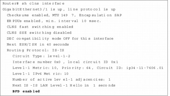
show clns interface will now show if an interface is enabled for BFD.
Figure 9. show clns interface
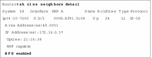
show clns neighbors detail has been enhanced to display if a particular neighbor is being monitored by BFD:
Figure 10. show clns neighbors detail
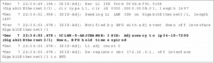
Finally, debug isis adj-packets will incorporate some additional output to show when IS-IS registers or de-registers with BFD.
Figure 11. debug isis adj-packets
CONCLUSION
Bidirectional Forwarding Detection provides a method for network administrators to configure sub-second Layer 2 failure detection between adjacent network nodes. Furthermore, they can configure their routing protocols to respond to BFD notifications, and begin Layer 3 route convergence almost immediately.
Provided that the appropriate caveats mentioned in this document are followed, BFD can be a powerful tool and an important part of a network-wide availability plan.
[an error occurred while processing this directive]