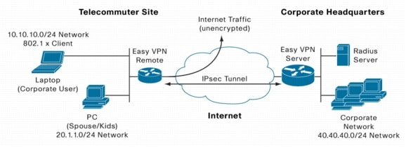
This document illustrates how to combine 802.1x authentication with Easy VPN Remote operating in client mode on Cisco IOS Software routers. A typical application of this combination is a teleworker solution (Figure 1). The access router (Cisco 871 Router in this example) provides connectivity from the teleworker location to the corporate network via an Easy VPN tunnel through the Internet. However there may also be other PCs in the teleworker location that are not part of the corporate network and hence should not be allowed into the VPN. Typical examples would be PCs used by the spouse or children of the teleworker. These PCs do need Internet access, and users are likely to leverage the teleworker router to avoid installing a second broadband connection in the same home. The combination of Cisco IOS® Easy VPN with 802.1x authentication enables enterprise employees, such as this teleworker, to access their corporate network, while limiting the access of other household members to the Internet. Such a configuration, known as "split tunneling", supports some PCs using the VPN tunnel while others can only access the Internet. This solution could also be used in a branch office, where each PC must authenticate using 802.1x before they can use the VPN.
Figure 1. Cisco 871 Easy VPN Client
VPN ACCESS CONTROL USING 802.1X AUTHENTICATION FEATURE IN EASY VPN CLIENT MODE
In this example, the general idea is to have the IPsec tunnel up at all times, and to use 802.1x to authenticate corporate users who try to gain access from the remote site. A RADIUS server at the headquarters site holds the database of corporate users. As the tunnel is always available, the remote router can query the database to confirm user/802.1x credentials (username/password) as necessary. This example uses Easy VPN operating in "Client" mode, which means that Port Address Translation (PAT) is used on the remote router to translate the addresses of all PCs at the remote site. In Easy VPN Client mode, the remote router is given a single address on the corporate network via policy push from the Easy VPN server when the IPsec tunnel connects. Corporate PCs at the remote side have their IP addresses PAT'd to this pushed corporate address when they access the central site over the VPN tunnel. Similarly, PCs used exclusively for Internet access, rather than access to the corporate network (e.g. spouse/kids PCs), have their addresses PAT'ed to the public interface address of the remote router, which is typically dynamically assigned by the Internet Service Provider.
The remote router, which is a Cisco 871 Router in this example, will have Internet connectivity via a broadband connection (ie: DSL or cable modem). The Easy VPN Remote (or "client") feature on the Cisco 871 Router automatically initiates the VPN tunnel towards the corporate network and the Easy VPN Server. In this example, the Easy VPN Server is a Cisco 1751 Router at headquarters. This Easy VPN server pushes the IPsec policy to the Easy VPN client (Cisco 871 Router) after completing both IKE and Xauth authentication with the Cisco 871 Router. In this example, the Xauth user name and password (which correspond to the Cisco 871 Router itself, not the PCs behind it) are stored in the configuration file on the Cisco 871 Router.
Enabling the 802.1x authentication feature at the Cisco 871 Router (Easy VPN Remote) is used to authenticate which PCs are allowed to use the VPN tunnel. Any PC that needs to access the corporate network via the VPN tunnel must run 802.1x client software (an 802.1x "supplicant"), with the appropriate user login information and password required to access the corporate network. Some newer operating systems include the supplicant by default (e.g. Windows XP) but it must be configured.
The 802.1x PCs (in this case the corporate teleworker PCs) send user credentials to the Cisco 871 Router at Layer 2 of the OSI model using the 802.1x protocol. Unauthenticated users (ie: PCs accessed by household member) will be allowed to access the Internet unencrypted, but will be blocked from accessing the corporate VPN tunnel.
Finally, it is possible enable 802.1x, and still allow devices to access the VPN even if they lack 802.1x capability. This is done by enabling bypass of 802.1x based on the MAC address of the device. In the case of Cisco IP Phones, it can also be done by enabling Cisco IP Phone to bypass (which uses the Cisco CDP protocol to discover the Cisco IP Phones).
PREREQUISITES
The sample configuration of the VPN access control using 802.1x authentication with Easy VPN is based on the following assumptions:
• One or more of the PCs (Employee PC) connecting behind the Cisco 871 should have 802.1X client software running on it.
• You should know how to configure authentication, authorization, and accounting (AAA) and RADIUS.
• User is familiar with IP Security (IPsec) based VPN.
• User is familiar with Dynamic Host Configuration Protocol (DHCP).
• User knows how to configure user lists on a Cisco access control server (ACS), assuming ACS is used as the RADIUS database.
COMPONENTS USED
The sample configuration uses the following releases of the software and hardware:
• Cisco 871 Router with Cisco IOS Software Release 12.4(4)XC
1. Enable 802.1x authentication on all teleworker PCs needing access to the corporate VPN.
2. Configure the Cisco 871 Router for Easy VPN Remote operation and 802.1x.
3. Configure the Cisco 1751 Router for Easy VPN Server operation.
________________________________________
Step 1. Enable 802.1x authentication on all teleworker PCs needing access to the corporate VPN
• If running Windows 2000, make sure that the PC has at least Service Pack 3.
Go to the page "Microsoft 802.1x Authentication Client" on the Microsoft Windows 2000 website at the following URL: http://www.microsoft.com/windows2000/server/evaluation/news/bulletins/8021xclient.asp.
At the above site, download and install 802.1X client for Windows 2000.
Reboot your PC after installing the client.
• Go to the Microsoft Windows registry and add or install the following entry: "HKLM\Software\Microsoft\EAPOL\Parameters\General\Global\SupplicantMode REG_DWORD 3"
("SupplicantMode" key entry is not there by default under Global option in the registry. So add a new entry named "SupplicantMode" as REG_DOWORD and then set its value to 3.)
• Reboot your PC.
To enable 802.1X authentication on Windows 2000 or Windows XP PCs perform the following steps.
________________________________________
Step 1. Open the Network and Dial-up Connections window on your computer.
Step 2. Right click the Ethernet interface (Local Area Connection) to open the properties window.
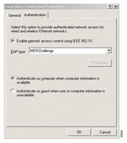
Click the "Authentication" tab. Select the check box titled "Enable network access control using IEEE 802.1X."
A Windows 2000dialog box will appear in a short time, or a floating window will ask you to select it. Select this option and enter a username and password in this dialog box when prompted.
Figure 2. Local Area Connection Properties Window
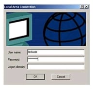
The EAP-MD5 port authentication process will begin after a short time and the user will be prompted to enter their Local Area Connection credentials (username and password).
• Enter the User Name and Password information required to authenticate to the Radius Server at Corporate Network.
• The Logon Domain information is not required.
Figure 3. Local Area Connection Credential Request
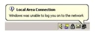
If the radius server validates the authentication credentials, the client can access the network. If the server does not validate the authentication credentials, a message similar to the following will be displayed:
The EAP-MD5 authentication will timeout and the user will be prompted for their authentication credentials again.
Figure 1 illustrates the network for the sample configuration.
CISCO 871 ROUTER (EASY VPN REMOTE) CONFIGURATION
version 12.3
no service pad
service timestamps debug datetime msec
service timestamps log datetime msec
no service password-encryption
!
hostname 871
!
enable secret 5 $1$1KBS$x6Iph6higJK.MF7IGKb9s0
!
clock timezone PST -8
clock summer-time PST recurring
aaa new-model
!
!
! --Creates an 802.1X port-based authentication method list
aaa authentication dot1x default group radius
aaa session-id common
ip subnet-zero
no ip domain lookup
ip domain name cisco.com
!
! --Specify the DHCP pool for Teleworker
ip dhcp pool Teleworker
network 10.10.10.0 255.255.255.0
default-router 10.10.10.1
dns-server 40.40.40.91 ! Corporate DNS
!
! --Specify the DHCP pool for HomePCs
ip dhcp pool Home-PCs
network 20.1.1.0 255.255.255.0
default-router 20.1.1.1
dns-server 192.168.1.1 !ISP DNS
!
! --Creates an identity profile and enters dot1x profile configuration mode.
identity profile default
! --Specifies the virtual template interface that will serve as the configuration clone source for the virtual interface that is dynamically created
! -- Enables periodic reauthentication of the supplicants on the interface
dot1x reauthentication
!
crypto ipsec client ezvpn crws-client
! --Connects the VPN tunnel automatically (which is by default)
connect auto
! -- Specifies the IPsec group and IPsec key value to be associated with this configuration.Specifies the IPsec group and IPsec key value to be associated with this configuration
group hw-client-groupname key 0 cisco
! --Specifies that the router is configured for VPN client operation, using NAT/PAT
address translation.
mode client
! --Specifies the IP address or hostname for the destination peer.
peer 30.30.30.2 !
!
! --Multiple DHCP pool requires additional loopback interface
interface Loopback100
ip address 20.1.1.1 255.255.255.0
ip nat inside!
!
!
interface FastEthernet0
!
interface FastEthernet1
!
interface FastEthernet2
!
interface FastEthernet3
!
interface FastEthernet4
description public network
ip address 30.30.30.1 255.255.255.0 duplex auto
ip nat outside
! --Assigns the Cisco Easy VPN Remote configuration to the interface. This automatically creates the necessary NAT/PAT translation parameters and initiates the VPN connection
crypto ipsec client ezvpn crws-client
interface Vlan1
description private network
ip address 10.10.10.1 255.255.255.0
! --Sets the port control value.auto (optional)-Authentication status of the supplicant will be determined by the authentication process.
dot1x pae authenticator
dot1x port-control auto
dot1x timeout reauth-period 36000
dot1x reauthentication
crypto ipsec client ezvpn crws-client inside
!
! --Creates a virtual template interface that can be configured and applied dynamically in creating virtual access interfaces
interface Virtual-Template1
! --Using loopback as ip unnumbered
ip unnumbered loopback100
ip access-group 105 in
ip nat inside
!
ip classless
ip route 0.0.0.0 0.0.0.0 FastEthernet4
! --Configure pat for the non-802.1x clients to access Internet
ip nat inside source list 140 interface FastEthernet4 overload
!
ip radius source-interface vlan1
! --ACL for preventing non-802.1x clients to access corporate network
access-list 105 deny ip any 40.40.40.0 0.0.0.255
access-list 105 permit ip any any
! --ACL for the pating the non-802.1x to access Internet
If you're using an IOS release prior to 12.4(9)T, please refer to the following section on DHCP and DNS configurations with 802.1x.
When configuring 802.1x, you have two options for DHCP address pools. You can either use a single pool for both the corporate and non-corporate PCs, or you can use a different pool for each one. The recommended solution is to use two pools, as in the example above. If you use two pools, the DNS server in the corporate DHCP pool should point to the corporate DNS server. The DNS server for the non-corporate user pool should use the DNS server provided by the ISP on the public interface.
There is one caveat on using the two pool solution: the 802.1x PC clients must correctly process the 802.1x login and request an IP address after authentication. Some 802.1x implementations do not do this: they request their IP address before authentication, and the user must manually refresh their address (i.e. new DHCP request) after authentication. As of this writing, Window XP SP1 correctly processes 802.1x, but Windows 2000 does not and requires a manual refresh. The AEGIS client from Meetinghouse Data Communications (www.mtghouse.com) has been tested successfully with the two pool solution.
If a single DHCP pool solution is used instead (for example, to work around the 802.1x client refresh problem), then it is recommended to use the "corporate" DNS server for all clients (both "corporate" PCs that authenticate with 802.1x, and other PCs that do not). The reason for this is that users can only point to a single primary DNS server for all the clients (because there is only one DHCP pool). Corporate PCs must point to the corporate DNS server so that they can resolve corporate internal domains. That means all the clients must point to this DNS server, including those that are not authenticated into the corporate network.
To allow non-authenticated clients to access the corporate DNS server in the single-pool solution, you must configure additional access-lists permitting tcp/udp port 53 (i.e. DNS) access to corporate DNS Server within the virtual-termplate1 interface (which is for the non-authenticated clients) as shown in the example below.
An alternate solution for DNS in the single-pool solution is to configure a primary and secondary DNS server in the DHCP pool, and have the primary server point to the DNS server in the Internet (learned on the public-facing interface). The secondary DNS server is configured for the corporate DNS server. The disadvantage of this is that all DNS requests from corporate authenticated PCs for corporate domains will first be sent to the public DNS server, will time out (because the public server cannot respond to them), and then a second request will be sent from the PC to the secondary (corporate) DNS server to be processed. The time out delay may or may not be acceptable for the users.
Example (Single DHCP Pool; Corporate DNS Server Used for All Clients):
ip dhcp pool client
network 10.10.10.0 255.255.255.0
default-router 10.10.10.1
dns-server 40.40.40.91
Interface virtual-template1
ip unnumbered vlan1
ip access-group 105 in
ip nat inside
access-list 105 permit tcp any host 40.40.40.91 eq domain
access-list 105 permit udp any host 40.40.40.91 eq domain
access-list 105 deny ip any 40.40.40.0 0.0.0.255
access-list 105 permit ip any any
interface Virtual-Template1
ip unnumbered vlan1
ip access-group 105 in
ip nat inside
Enabling MAC-Address Based 802.1x Bypass
If you have devices on the private network that need access to the VPN tunnel but do not have an 802.1x supplicant (ie: IP Phone), you can configure the solution to allow them access based on their MAC addresses. The MAC addresses can either be configured manually on each router doing 802.1x that the devices will plug into, or you can centralize the MAC addresses on the RADIUS server (for example, Cisco ACS). In the centralized method, the remote routers enabled for 802.1x will query RADIUS for MAC bypass whenever they encounter a device trying to access an 802.1x enabled port but lacking 802.1x supplicant capability. The centralized method is preferred because in that case all the administration is done in one place, and a particular device can plug into any remote router and get authenticated, without that device's address having to be statically configured on every router.
For guidelines on how to configure MAC address bypass using MAC address configured on the 802.1x remote routers, see the 802.1x Feature Guide in the References section of this document. This document also explains how to enable bypass for Cisco IP Phones using the CDP protocol.
To enable centralized MAC address bypass on the RADIUS server, no configuration of any kind is required on the remote routers. All that is needed is to create an account in the RADIUS server database for each MAC address that needs to bypass 802.1x. When creating these user accounts, the MAC address is entered for both the username and password, with no punctuation or special characters. Any letters (a-f) in the address must be in lower-case. For example: username and password = "00028ade60aa".
! --Define the username and password to be used for X-Auth
username cisco password 0 cisco
memory-size iomem 25
! --Enable Authentication, Authorizing and Accounting (AAA) for user authentication and group authorization.
aaa new-model
! --Enable X-Auth for user authentication using aaa authentication
aaa authentication login userlist local
! --Enable group authorization using aaa authorization
aaa authorization network hw-client-groupname local
aaa session-id common
ip subnet-zero
!
!
no ip domain lookup
ip domain name cisco.com
ip dhcp excluded-address 40.40.40.1
!
! --Specify the network number and mask for DHCP clients i.e. DHCP for corporate network.
ip dhcp pool Corporate
network 40.40.40.0 255.255.255.0
default-router 40.40.40.1
dns-server 40.40.40.91 ! Corporate DNS
!
!
ip cef
ip audit notify log
ip audit po max-events 100
ip ssh break-string
!
! --Create an Internet Security Association and Key Management Protocol (ISAKMP) policy for Phase 1 negotiations.
.
crypto isakmp policy 1
encr 3des
authentication pre-share
group 2
!
! --Specifies the DHCP pool to be used for Easy VPN clients
crypto isakmp client configuration address-pool local dynpool
crypto isakmp xauth timeout 60
!
! --Create a group that will be used to specify the Windows Internet Naming Service (WINS) and Domain Naming Service (DNS) server addresses to the client, along with the pre-shared key for IKE authentication
crypto isakmp client configuration group hw-client-groupname
! --Specifies the IKE preshared key (which is cisco) for group policy attribute definition
key cisco
! --Defines a local pool address
pool dynpool
! --(Optional) Configures split tunneling (ACL 180 is the list of headquarters subnets that need to be reached via the VPN tunnel)
acl 180
!
!--- Create the Phase 2 policy for actual data encryption.
! --Tie the dynamic crypto map to the public interface
crypto map dynmap
!
interface Ethernet1/0
description private network
ip address 40.40.40.1 255.255.255.0
! --Specify IP address pools for internal IP address allocation to Easy VPN clients (e.g. the remote 871, or software clients)
ip local pool dynpool 40.40.40.50 40.40.40.60
ip classless
ip route 0.0.0.0 0.0.0.0 FastEthernet0/0
!
!
! --Create ACL for split-tunneling
access-list 180 permit ip 40.40.40.0 0.0.0.255 any
!
!
control-plane
!
!
line con 0
line aux 0
line vty 0 4
!
no scheduler allocate
!
end
Verifying the Results
Use the information in this section to confirm that the configuration is working properly:
Verifying the Cisco 871 Router Status (Easy VPN Client)
! --The following command shows the Internet Security Association Management Protocol (ISAKMP or IKE) Security Association (SA) built between peers. QM_IDLE means that the IKE connection is up.
871#show crypto isakmp sa
dst src state conn-id slot
30.30.30.2 30.30.30.1 QM_IDLE 3 0
! -- This command shows an active Easy VPN connection
871# show crypto ipsec client ezvpn
Easy VPN Remote Phase: 2
Tunnel name : crws-client
Inside interface list: Ethernet0,
Outside interface: Ethernet1
Current State: IPSEC_ACTIVE
Last Event: SOCKET_UP
Address: 40.40.40.50
Mask: 255.255.255.255
Split Tunnel List: 1
Address : 40.40.40.0; this subnet is at the headquarters location and traffic to this subnet is sent via the tunnel. ALL other traffic is sent in the clear to the Internet (with PAT applied).
Mask : 255.255.255.0
Protocol : 0x0
Source Port: 0
Dest Port: 0
! --The following command shows the summary of ike and ipsec security associations.
871# show crypto session
Crypto session current status
Interface: Ethernet1
Session status: UP-ACTIVE
Peer: 30.30.30.2/500
IKE SA: local 30.30.30.1/500 remote 30.30.30.2/500 Active
IPSEC FLOW: permit ip host 40.40.40.50 40.40.40.0/255.255.255.0
Active SAs: 2, origin: crypto map
! --The following command shows IPsec SA built between peers. The encrypted tunnel is built between 30.30.30.1and 30.30.30.2 for traffic going between networks 40.40.40.50/32 and 40.40.40.0/24. You can see the two Encapsulating Security Payload (ESP) SAs built inbound and outbound. (You can also use "show crypto session" for a simpler display.) 871# show crypto ipsec sa
interface: Ethernet1
Crypto map tag: Ethernet1-head-0, local addr. 30.30.30.1 protected vrf:
local ident (addr/mask/prot/port): (40.40.40.50/255.255.255.255/0/0)
sa timing: remaining key lifetime (k/sec): (4575407/3376)
IV size: 8 bytes
replay detection support: Y
outbound ah sas:
outbound pcp sas:
! --The following command display 802.1X statistics, administrative status, and operational status for the specified interface which is E0 in this case.
871# show dot1x int e0 det
PortControl = AUTO
ReAuthentication = Enabled
ReAuthPeriod = 36000 Seconds
ServerTimeout = 30 Seconds
SuppTimeout = 30 Seconds
QuietWhile = 120 Seconds
RateLimit = 0 Seconds
MaxReq = 2
Dot1x Client List
-------------------------------------
MAC Address State
-------------------------------------
0009.6b7a.6870 UNAUTHENTICATED
0060.b0f1.99a9 AUTHENTICATED
Verifying the 1751 Status (Easy VPN Server)
! --The following command shows the Internet Security Association Management Protocol
(ISAKMP) Security Association (SA) built between peers.
1751#show crypto isakmp sa
dst src state conn-id slot
30.30.30.2 30.30.30.1 QM_IDLE 1 0
! --The following command shows the summary of ike and ipsec security associations.
1751#show crypto session
Crypto session current status
Interface: FastEthernet0/0
Session status: UP-ACTIVE
Peer: 30.30.30.1/500
IKE SA: local 30.30.30.2/500 remote 30.30.30.1/500 Active
IPSEC FLOW: permit ip 40.40.40.0/255.255.255.0 host 40.40.40.50