[an error occurred while processing this directive]

IPSec Negotiation/IKE Protocols

Configuring DMVPN Spoke Router in Full Mesh IPsec VPN Using SDM

WHITE PAPER

This document provides a sample configuration for configuring Dynamic Multipoint spoke router into a full mesh Dynamic Multipoint VPN (DMVPN). DMVPN allows users to scale large and small IPsec VPNs more effectively by combining generic routing encapsulation (GRE) tunnels, IPsec encryption, and Next Hop Resolution Protocol (NHRP). Security Device Manager (SDM) is an embedded security configuration management tool used to configure Cisco IOS® Software routers with variety of security features. This sample configuration relies on SDM version 1.2 that supports hub and spoke DMVPN configurations and shows how to configure dynamic Spoke to Spoke tunnels.

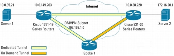
Figure 1. Network Diagram

FULL MESH DMVPN BENEFITS

Automatic IPsec Encryption Initiation

GRE has the peer source and destination address configured or resolved with NHRP. Thus, this feature allows IPsec to be immediately triggered for the point-to-point GRE tunneling or when the GRE peer address is resolved via NHRP for the multipoint GRE tunnel.

Support for Dynamically Addressed Spoke Routers

When using point-to-point GRE and IPsec hub-and-spoke VPN networks, the physical interface IP address of the spoke routers must be known to configure the hub router, because IP address should be configured as the GRE tunnel destination address. This feature allows spoke routers to have dynamic physical interface IP addresses (common for cable and DSL connections). When the spoke router comes online it sends registration packets to the hub router. The current physical interface IP address of this spoke is located within these registration packets.

Dynamic Tunnel Creation for Spoke-to-Spoke Tunnels

This feature eliminates the need for spoke-to-spoke configuration to enable direct tunnels. When a spoke router wants to transmit a packet to another spoke router it can now use NHRP to dynamically determine the required destination address of the target spoke router. (The hub router acts as the NHRP server, handling the request for the source spoke router.) The two spoke routers dynamically create an IPsec tunnel between them, so the data can be directly transferred.
This configuration utilizes SDM version 1.2. The wizard in SDM version 1.2 supports only hub and spoke DMVPN configuration. This configuration guide will first configure the spoke with hub and spoke mode only and then modify the spoke configuration using the advanced mode to enable the full mesh DMVPN configuration to the spoke.
Although the spoke can be configured directly from the advanced mode, configuring the spoke in the wizard mode ensures the creation of policies and additional configuration checks.

PREREQUISITES

The sample configuration is based on the following assumptions:

• Public IP address of the hub, this configuration is using 10.0.38.219.

• IP address of the IPsec tunnel on the hub, this configuration is using 192.168.1.219.

• IP address of the IPsec tunnel on the local spoke, this configuration is using 192.168.1.220.

• Physical IP address assignment and any required DHCP pool for local users.

• The Routing protocol is used with the hub router, this configuration is using Enhanced Interior Gateway Routing Protocol (EIGRP).

• An assigned pre-shared key that will be used on all the dynamic spokes.

LIMITATIONS

This guide configures the spoke router for DMVPN only. It does not cover the following configuration:

• Full security audit on the router. It is recommended to run Security Audit in the wizard mode to lock down and secure the router.

• An initial router configuration step is not shown under the steps section. The full configuration is show in a following section.

• The hub router must propagate a default route to the remote spokes with the IP routing protocol for accessing the internet. It also must handle all the firewall and network address translations requirements.

BEFORE THE BEGINNING OF CONFIGURATIONS

Before the beginning of configurations, make sure of the following:

• The spoke router can reach the DMVPN hub, and the DMVPN hub is configured and operational.

• SDM is loaded on the router flash memory, and the http configuration is enabled on the router. For additional information on configuring and using SDM, please refer to: http://www.cisco.com/go/sdm.

COMPONENTS USED

The sample configuration uses the following Cisco IOS Software releases and hardware:

• Cisco IOS Software Release 12.3(8)T, Cisco 831 Series Router (C831-K9O3SY6-M)

• Cisco Router and Security Device Manager (SDM) Version 1.2

The network for the sample configuration is illustrated in the Figure 1.
The information presented in this document was obtained from the devices in a specific lab environment. All of the devices started with a cleared (default) configuration. In a live network it is imperative to understand the potential impact of any command before implementing it.

CONFIGURING THE SPOKE ROUTER WITH SDM

Follow the steps in this section to configure the Spoke router with SDM.
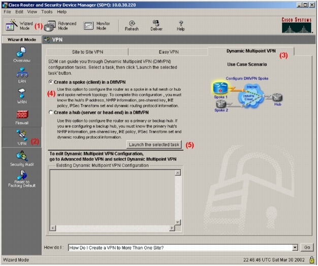
Step 1: SDM Window

From the SDM on the spoke router, make the following selections in this order:

1. Wizard Mode

2. VPN icon

3. DMVPN

4. Create a spoke (client) in a DMVPN option

5. Launch the Selected Task button to launch the DMVPN Wizard

The selections in Step 1 are outlined in the following diagram:

Note: The VPN wizard in SDM version 1.2 supports only one IPsec VPN configuration on the router. SDM will attempt to detect any existing VPN configuration. The advanced mode can be used to edit or delete the existing VPN configuration.

Step 3: Configure a DMVPN Spoke Window

Review the provided information and select Next.

Step 4: DMVPN Network Topology

Select Hub and Spoke option and than Next. (Note: this is the only option in SDM version 1.2)

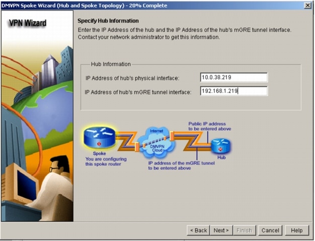
Step 5: Specify Hub Information

Enter the public IP Address of the hub and IP Address of the Hub mGRE tunnel interface, as showed in the following diagram and then select next.

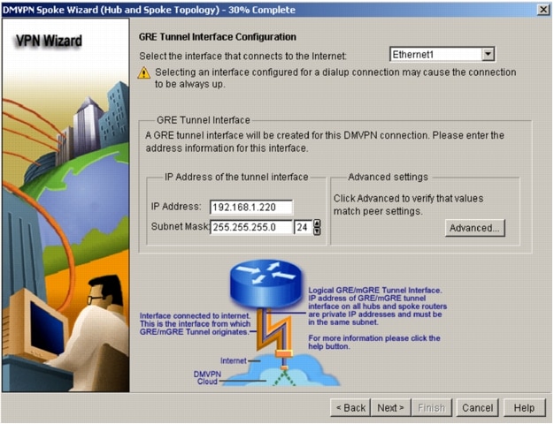
Step 6: GRE Tunnel Interface Configuration

Select the interface that connects to the internet, enter the assigned IP address and mask of the tunnel interface, and Select Advanced button in the Advanced settings section.

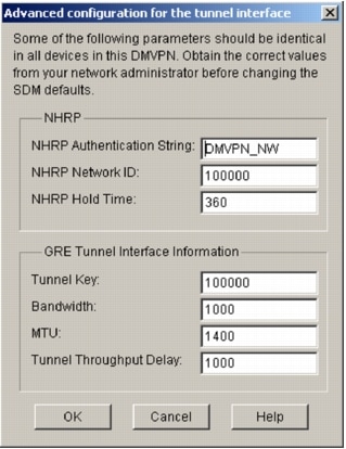
Step 7: Advanced Configuration for the Tunnel Interface

Review the defaults Advanced settings of the DMVPN configuration to verify that they match the configuration required by the hub router. Select OK button to return to the GRE Tunnel Interface Configuration, then select next to proceed to the wizard.

Note: The previous diagram shows the default settings of SDM. Use the default configuration if it matches the DMVPN hub router.

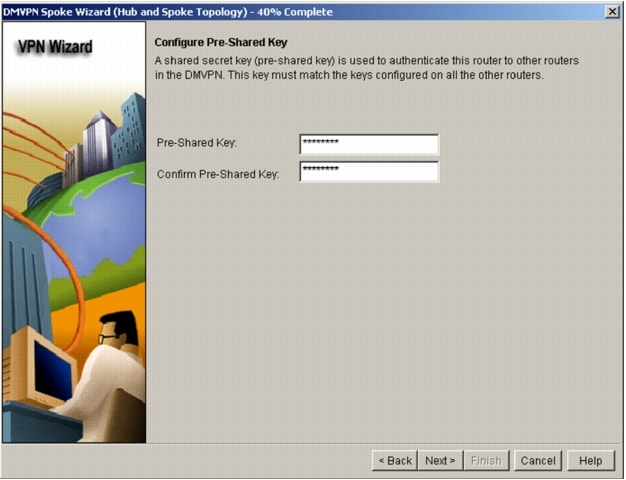
Step 8: Configure Pre-Shared Key

Enter and confirm the pre-shared key with the DMVPN hub, then select the Next button.

Note: If the pre-shared key with the hub is already configured, the new pre-shared key can not be entered in this step.

Step 9: Key Exchange Policy

Review Key Exchange Policy to ensure it matches the DMVPN hub configuration and select next. SDM provides the following polices by defaults:

• Key Exchange Policy: 3DES encryption, SHA_1 Hash, D-H group 2, Authentication Pre-share.

Step 10: Transform Set

Review the IPsec Transform Set to ensure that it match the DMVPN hub configuration and select next. SDM provides the following polices by defaults:

• IPsec Transform Set: ESP with 3DES encryption, ESP with SHA integrity check.

Step 11: Select Routing Protocol

Review and select the IP routing protocol. This configuration utilized EIGRP. Select next.

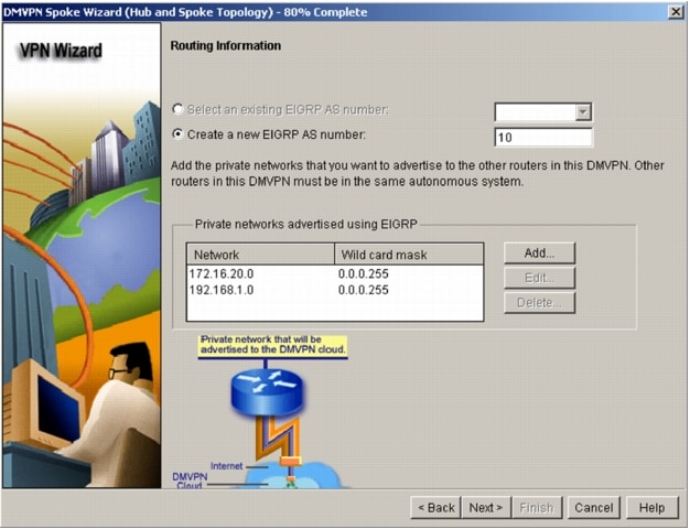
Step 12: Routing Information

Select an existing routing process or create a new one. This step enables the routing protocol for the selected interfaces and advertises the private network with the selected routing protocol. In this case the subnet 172.16.20.0/24 is connected to the local private interface. The 192.168.1.0/24 is the DMVPN tunnel interface.

Note: Adding the tunnel interface subnet to the private networks advertised is optional, as SDM automatically adds this subnet to the routing protocol. Also, the wild card mask for this subnet may not show in the previous window.

Step 13: Summary of the Configuration

Review the final configuration and select Finish button to start the delivery process. Following are the configuration created by SDM:
crypto ipsec transform-set SDM_TRANSFORMSET_6 esp-sha-hmac esp-3des
mode tunnel
exit
crypto ipsec profile SDM_Profile6
set transform-set SDM_TRANSFORMSET_6
exit
interface Tunnel0
bandwidth 1000
delay 1000
ip nhrp holdtime 360
ip nhrp network-id 100000
ip nhrp authentication DMVPN_NW
ip mtu 1400
no shutdown
ip address 192.168.1.220 255.255.255.0
ip nhrp nhs 192.168.1.219
ip nhrp map 192.168.1.219 10.0.38.219
tunnel source Ethernet1
tunnel destination 10.0.38.219
tunnel protection ipsec profile SDM_Profile6
tunnel key 100000
exit
router eigrp 10
no auto-summary
network 172.16.20.0 0.0.0.255
network 192.168.1.0 0.0.0.255
exit
crypto isakmp key ******** address 10.0.38.219

Note: Also by this step, the configuration wizard have created the setup of this spoke into the DMVPN network. This spoke will have access to all the other spokes and the rest of the network. However, all communication by this spoke passed through the hub.

Step 14: Deliver Configuration to the Router

Select the deliver button to send the configuration to the router. When completed, select OK.

Note: When configuration is delivered to the router it is not saved to the startup-configs, unless that option was specified during the configuration delivery process.
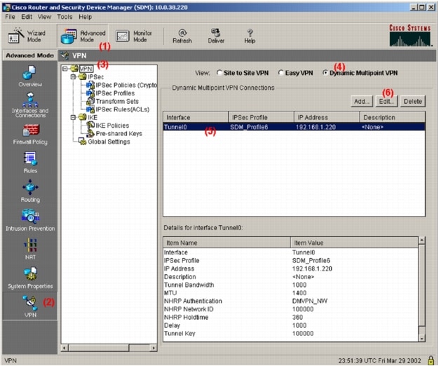
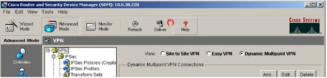
Step 15: SDM Window

This step will begin to modify the router configuration to enable direct spoke to spoke tunnel setup. Make the following steps in the same order:

1. Advanced Mode

2. VPN

3. Root VPN item

4. Dynamic Multipoint VPN

5. Tunnel Interface

6. Edit

This sequence of selection will open the DMVPN Tunnel Configuration dialog box.

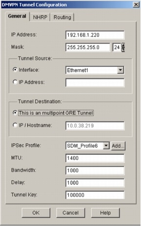
Step 16: DMVPN Tunnel Configuration-General Tab

Select "This is a multipoint GRE Tunnel" under the General Tab and then select the NHRP tab.

Step 17: DMVPN Tunnel Configuration-NHRP Tab

Under the NHRP tab, select the Add button under the NHRP MAP section. This will open up the following NHRP Map Configuration dialog box.

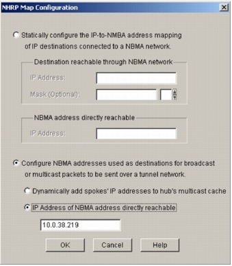
Step 18: NHRP Map Configuration

Select "Configure NBMA addresses", which is used as destinations for broadcast or multicast packets, then select "IP Address of NBMA address directly reachable" and enter the public address of the hub router. The following diagram shows current selections. Finally, choose OK button.

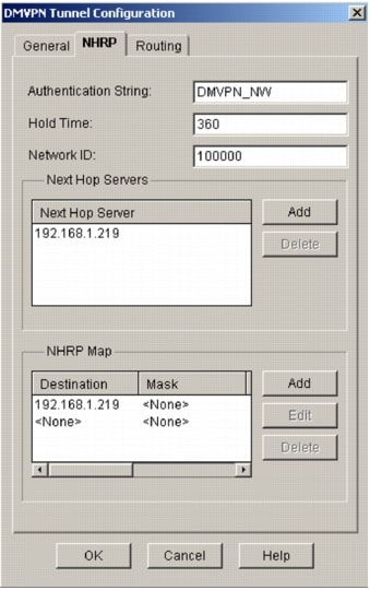
Step 19: DMVPN Tunnel Configuration

Following is the NHRP tab after enabling the NHRP dynamic spokes. Select "OK" to return to the Advanced Mode.

Step 20: SDM Window

This step will configure a pre-shared Key for dynamic spokes. Make the following steps in the same order:

1. Advanced Mode

2. VPN

3. IKE: Pre-shared Key

4. Add.

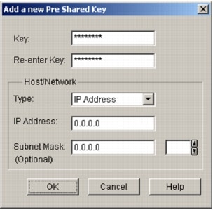
This sequence of selection will open the "Add new Pre-Shared Key" Configuration dialog box. Enter the information and select OK.

Step 21: Select Deliver as showed in (*) to update the router configuration and then select deliver again under the pop up window.

The following are the modification generated by steps 15 through 21:
crypto isakmp key 0 ******** address 0.0.0.0 0.0.0.0
interface Tunnel0
ip nhrp map multicast 10.0.38.219
no tunnel destination
tunnel mode gre multipoint
exit

Note: When configuration is delivered to the router it is not saved to the startup configs, unless that option was specified during the configuration delivery process.

Router Configurations:
c831-20#sh run
Building configuration...
Current configuration : 3174 bytes
!
version 12.3
no service pad
service timestamps debug uptime
service timestamps log uptime
service password-encryption
!
hostname c831-20
!
boot-start-marker
boot system flash:c831-k9o3sy6-mz.123-8.T.bin
boot-end-marker
!
no logging buffered
enable password 7 105D0D14
!
username sdm privilege 15 password 7 105D0D14
no aaa new-model
ip subnet-zero
!
!
ip dhcp excluded-address 10.10.10.1
!
ip dhcp pool CLIENT
import all
network 10.10.10.0 255.255.255.0
default-router 10.10.10.1
lease 0 2
!
!
ip ips po max-events 100
no ftp-server write-enable
!
!
crypto isakmp policy 1
encr 3des
authentication pre-share
group 2
crypto isakmp key cisco123 address 10.0.38.219
crypto isakmp key cisco123 address 0.0.0.0 0.0.0.0
!
crypto ipsec transform-set SDM_TRANSFORMSET_1 esp-3des esp-sha-hmac
!
crypto ipsec profile SDM_Profile1
set transform-set SDM_TRANSFORMSET_1
!
!
interface Tunnel0
bandwidth 1000
ip address 192.168.1.220 255.255.255.0
no ip redirects
ip mtu 1400
ip nhrp authentication DMVPN_NW
ip nhrp map 192.168.1.219 10.0.38.219
ip nhrp map multicast 10.0.38.219
ip nhrp network-id 100000
ip nhrp holdtime 360
ip nhrp nhs 192.168.1.219
delay 1000
tunnel source Ethernet1
tunnel mode gre multipoint
tunnel key 100000
tunnel protection ipsec profile SDM_Profile1
!
interface Ethernet0
ip address 172.16.20.220 255.255.255.0
no cdp enable
!
interface Ethernet1
ip address 10.0.38.220 255.255.255.0
ip virtual-reassembly
duplex auto
no cdp enable
!
interface FastEthernet1
no ip address
duplex auto
speed auto
!
interface FastEthernet2
no ip address
duplex auto
speed auto
!
interface FastEthernet3
no ip address
duplex auto
speed auto
!
interface FastEthernet4
no ip address
duplex auto
speed auto
!
router eigrp 10
network 172.16.20.0 0.0.0.255
network 192.168.1.0
no auto-summary
!
ip classless
ip route 0.0.0.0 0.0.0.0 128.107.162.1
ip route 10.0.0.0 255.255.255.0 10.0.38.219
!
ip http server
ip http authentication local
ip http secure-server
!
access-list 23 permit 10.10.10.0 0.0.0.255
access-list 102 permit ip 10.10.10.0 0.0.0.255 any
!
control-plane
!
!
line con 0
line aux 0
line vty 0 4
exec-timeout 0 0
password 7 095F4A04
login
transport preferred all
transport input all
transport output all
!
end
c831-20#

VERIFYING THE RESULTS

This section provides information that can be used to confirm that configuration is working properly.
Use the "show crypto session detail" command to verify that IPsec tunnel is established with the hub router. After installing the configuration, only IPsec session to the hub should become active.
c831-20#show crypto session detail
Crypto session current status
Code: C - IKE Configuration mode, D - Dead Peer Detection
K - Keepalives, N - NAT-traversal, X - IKE Extended Authentication
Interface: Tunnel0
Session status: UP-ACTIVE
Peer: 10.0.38.219/500 fvrf: (none) ivrf: (none)
Phase1_id: 10.0.38.219
Desc: (none)
IKE SA: local 10.0.38.220/500 remote 10.0.38.219/500 Active
Capabilities:(none) connid:2 lifetime:23:57:03
IPSEC FLOW: permit 47 host 10.0.38.220 host 10.0.38.219
Active SAs: 2, origin: crypto map
Inbound: #pkts dec'ed 49 drop 0 life (KB/Sec) 4383336/3425
Outbound: #pkts enc'ed 59 drop 3 life (KB/Sec) 4383338/3425
Use the "show ip nhrp" command to verify the static nhrp mapping to the hub.
c831-20#show ip nhrp
192.168.1.219/32 via 192.168.1.219, Tunnel0 created 00:01:19, never expire
Type: static, Flags: authoritative used
NBMA address: 10.0.38.219
Use the "show ip route" command to verify that routes are propagated from the hub router into the spoke routing table.
c831-20#show ip route
Codes: C - connected, S - static, R - RIP, M - mobile, B - BGP
D - EIGRP, EX - EIGRP external, O - OSPF, IA - OSPF inter area
N1 - OSPF NSSA external type 1, N2 - OSPF NSSA external type 2
E1 - OSPF external type 1, E2 - OSPF external type 2
i - IS-IS, su - IS-IS summary, L1 - IS-IS level-1, L2 - IS-IS level-2
ia - IS-IS inter area, * - candidate default, U - per-user static rout
o - ODR, P - periodic downloaded static route
Gateway of last resort is 128.107.162.1 to network 0.0.0.0
172.16.0.0/24 is subnetted, 4 subnets
C 172.16.20.0 is directly connected, Ethernet0
D 172.16.23.0 [90/16281600] via 192.168.1.223, 00:01:44, Tunnel0
D 172.16.19.0 [90/2944000] via 192.168.1.219, 00:01:44, Tunnel0
D 172.16.94.0 [90/15616000] via 192.168.1.219, 00:01:44, Tunnel0
172.19.0.0/32 is subnetted, 1 subnets
D EX 172.19.192.58 [170/3072000] via 192.168.1.219, 00:01:44, Tunnel0
10.0.0.0/8 is variably subnetted, 5 subnets, 3 masks
S 10.0.0.0/24 [1/0] via 10.0.38.219
D EX 10.0.0.0/8 [170/3072000] via 192.168.1.219, 00:01:44, Tunnel0
C 10.0.38.0/24 is directly connected, Ethernet1
D EX 10.82.0.0/16 [170/3072000] via 192.168.1.219, 00:01:44, Tunnel0
D EX 10.86.0.0/16 [170/3072000] via 192.168.1.219, 00:01:44, Tunnel0
C 192.168.1.0/24 is directly connected, Tunnel0
S* 0.0.0.0/0 [1/0] via 128.107.162.1
D EX 172.0.0.0/8 [170/3072000] via 192.168.1.219, 00:01:45, Tunnel0
D EX 128.0.0.0/8 [170/3072000] via 192.168.1.219, 00:01:45, Tunnel0
Ping a private segment on another spoke to bring up direct IPsec tunnel with that spoke.
c831-20#ping 172.16.23.223
Type escape sequence to abort.
Sending 5, 100-byte ICMP Echos to 172.16.23.223, timeout is 2 seconds:
..!!!
Success rate is 60 percent (3/5), round-trip min/avg/max = 8/14/20 ms
Use "show ip nhrp" command to verify the next hop resolution to the neighbor spoke:
c831-20#show ip nhrp
172.16.23.0/24 via 172.16.23.223, Tunnel0 created 00:00:02, expire 00:05:57
Type: dynamic, Flags: router unique
NBMA address: 10.0.38.223
192.168.1.219/32 via 192.168.1.219, Tunnel0 created 00:09:37, never expire
Type: static, Flags: authoritative used
NBMA address: 10.0.38.219
Use "show crypto session" command to check the status of IPsec session to the hub and to the first spoke
c831-20#sh cry sess
Crypto session current status
Interface: Tunnel0
Session status: UP-ACTIVE
Peer: 10.0.38.219/500
IKE SA: local 10.0.38.220/500 remote 10.0.38.219/500 Active
IPSEC FLOW: permit 47 host 10.0.38.220 host 10.0.38.219
Active SAs: 2, origin: crypto map
Interface: Tunnel0
Session status: UP-ACTIVE
Peer: 10.0.38.223/500
IKE SA: local 10.0.38.220/500 remote 10.0.38.223/500 Active
IPSEC FLOW: permit 47 host 10.0.38.220 host 10.0.38.223
Active SAs: 2, origin: crypto map
c831-20#show interface tunnel 0
Tunnel0 is up, line protocol is up
Hardware is Tunnel
Internet address is 192.168.1.220/24
MTU 1514 bytes, BW 1000 Kbit, DLY 10000 usec,
reliability 255/255, txload 1/255, rxload 1/255
Encapsulation TUNNEL, loopback not set
Keepalive not set
Tunnel source 10.0.38.220 (Ethernet1), destination UNKNOWN
Tunnel protocol/transport multi-GRE/IP, key 0x186A0, sequencing disabled
Checksumming of packets disabled, fast tunneling enabled
Tunnel transmit bandwidth 8000 (kbps)
Tunnel receive bandwidth 8000 (kbps)
Tunnel protection via IPSec (profile "SDM_Profile1")
Last input 00:00:00, output 00:00:02, output hang never
Last clearing of "show interface" counters never
Input queue: 0/75/2/0 (size/max/drops/flushes); Total output drops: 2
Queueing strategy: fifo
Output queue: 0/0 (size/max)
5 minute input rate 0 bits/sec, 0 packets/sec
5 minute output rate 0 bits/sec, 0 packets/sec
2370 packets input, 291454 bytes, 0 no buffer
Received 0 broadcasts, 0 runts, 0 giants, 0 throttles
0 input errors, 0 CRC, 0 frame, 0 overrun, 0 ignored, 0 abort
1863 packets output, 219665 bytes, 0 underruns
0 output errors, 0 collisions, 0 interface resets
0 output buffer failures, 0 output buffers swapped out

RELATED INFORMATION

IPsec Support Page

An Introduction to IP Security (IPsec) Encryption

Cisco IOS Easy VPN Client Feature

Cisco IOS Easy VPN Server

Configuring IPsec Network Security

Configuring Internet Key Exchange Security Protocol

Command Lookup Tool (registered customers only)

Technical Support - Cisco Systems

Text Box:  Corporate HeadquartersCisco Systems, Inc.170 West Tasman DriveSan Jose, CA 95134-1706USAwww.cisco.comTel: 408 526-4000    800 553-NETS (6387)Fax: 408 526-4100    European HeadquartersCisco Systems International BVHaarlerbergparkHaarlerbergweg 13-191101 CH AmsterdamThe Netherlandswww-europe.cisco.comTel:  31 0 20 357 1000Fax:    31 0 20 357 1100    Americas HeadquartersCisco Systems, Inc.170 West Tasman DriveSan Jose, CA 95134-1706USAwww.cisco.comTel:    408 526-7660Fax:    408 527-0883    Asia Pacific HeadquartersCisco Systems, Inc.168 Robinson Road#28-01 Capital TowerSingapore 068912www.cisco.comTel: +65 6317 7777Fax: +65 6317 7799Cisco Systems has more than 200 offices in the following countries and regions. Addresses, phone numbers, and fax numbers are listed onthe Cisco Web site at www.cisco.com/go/offices.Argentina · Australia · Austria · Belgium · Brazil · Bulgaria · Canada · Chile · China PRC · Colombia · Costa Rica · Croatia · Cyprus Czech Republic · Denmark · Dubai, UAE · Finland · France · Germany · Greece · Hong Kong SAR · Hungary · India · Indonesia · Ireland Israel · Italy · Japan · Korea · Luxembourg · Malaysia · Mexico · The Netherlands · New Zealand · Norway · Peru · Philippines · Poland Portugal · Puerto Rico · Romania · Russia · Saudi Arabia · Scotland · Singapore · Slovakia · Slovenia · South Africa · Spain · Sweden Switzerland · Taiwan · Thailand · Turkey · Ukraine · United Kingdom · United States · Venezuela · Vietnam · ZimbabweCopyright  2004 Cisco Systems, Inc. All rights reserved. Cisco, Cisco IOS, Cisco Systems, and the Cisco Systems logo are registered trademarks of Cisco Systems, Inc. and/or its affiliates in the United States and certain other countries.All other trademarks mentioned in this document or Web site are the property of their respective owners. The use of the word partner does not imply a partnership relationship between Cisco and any other company. (0402R) 204025.2_ETMG_AE_10.04Printed in the USA Text Box:  Corporate HeadquartersCisco Systems, Inc.170 West Tasman DriveSan Jose, CA 95134-1706USAwww.cisco.comTel:    408 526-4000    800 553-NETS (6387)Fax: 408 526-4100    European HeadquartersCisco Systems International BVHaarlerbergparkHaarlerbergweg 13-191101 CH AmsterdamThe Netherlandswww-europe.cisco.comTel:  31 0 20 357 1000Fax:    31 0 20 357 1100    Americas HeadquartersCisco Systems, Inc.170 West Tasman DriveSan Jose, CA 95134-1706USAwww.cisco.comTel:    408 526-7660Fax:    408 527-0883    Asia Pacific HeadquartersCisco Systems, Inc.168 Robinson Road#28-01 Capital TowerSingapore 068912www.cisco.comTel: +65 6317 7777Fax: +65 6317 7799Cisco Systems has more than 200 offices in the following countries and regions. Addresses, phone numbers, and fax numbers are listed onthe Cisco Web site at www.cisco.com/go/offices.Argentina · Australia · Austria · Belgium · Brazil · Bulgaria · Canada · Chile · China PRC · Colombia · Costa Rica · Croatia · Cyprus Czech Republic · Denmark · Dubai, UAE · Finland · France · Germany · Greece · Hong Kong SAR · Hungary · India · Indonesia · Ireland Israel · Italy · Japan · Korea · Luxembourg · Malaysia · Mexico · The Netherlands · New Zealand · Norway · Peru · Philippines · Poland Portugal · Puerto Rico · Romania · Russia · Saudi Arabia · Scotland · Singapore · Slovakia · Slovenia · South Africa · Spain · Sweden Switzerland · Taiwan · Thailand · Turkey · Ukraine · United Kingdom · United States · Venezuela · Vietnam · ZimbabweCopyright  2004 Cisco Systems, Inc. All rights reserved. Cisco, Cisco IOS, Cisco Systems, and the Cisco Systems logo are registered trademarks of Cisco Systems, Inc. and/or its affiliates in the United States and certain other countries.All other trademarks mentioned in this document or Web site are the property of their respective owners. The use of the word partner does not imply a partnership relationship between Cisco and any other company. (0402R) 204025.2_ETMG_AE_10.04Printed in the USA

[an error occurred while processing this directive]