The convergence of voice and data over existing data circuits has led enterprise network managers to consider whether to continue the deployment of hub-and-spoke circuit-switched services supported in-house, or to opt for a service-provider-managed Multiprotocol Label Switching (MPLS) IP VPN-based solution. Many enterprises are adopting the latter, only to find that where they hand off support of a network management infrastructure through managed customer edge devices, they must manage complex generic routing encapsulation (GRE) tunnels required to provide support for enterprise multicast (MCAST) traffic across non-MCAST-aware MPLS networks. This paper concentrates on one MCAST application-voice over IP (VoIP) music on hold (MOH). It compares a typical Frame Relay deployment of centralized Cisco® CallManager MCAST MOH against that of MCAST MOH through GRE tunnels traversing non-MCAST-aware MPLS service provider networks. It then highlights some current research into providing direct MCAST support over MPLS.
INTRODUCTION
Providing the ability to use existing data connectivity for voice traffic and to effectively gain "free" intra-office calling (on-net), VoIP has become a dominant enterprise business driver.
Many enterprise network managers have found that costs can be further reduced through the deployment of centralized media convergence servers (MCSs), such as Cisco CallManager. Through careful codec selection, MCSs can deliver "toll-quality" voice to low-bandwidth remote sites. However, the support of traffic engineering policies to ensure quality of service (QoS) guarantees to routing protocols, the call setup, and the calls themselves-while ensuring that packets are not marked "discard-eligible" as they cross the service provider network-becomes excessively complex.
VoIP must be able to deliver standard private branch exchange (PBX) services, such as MOH (Cisco CallManager Version 3.1 or higher). MOH is being increasingly used as an enterprise marketing tool, and is becoming a crucial technology support area. MOH streams music from an MOH server (typically the MCS) to the voice interfaces of on-net (IP-connected) and off-net (PSTN-connected) callers that have been placed on hold. In an MOH environment, whenever the on-net party places the other party on hold, the Cisco CallManager service requests the MOH server to stream Real-Time Protocol (RTP) packets to the "on-hold" interface through the preconfigured multicast address (MOH). MOH typically uses the PCM G.711 codec (A-law/(µ-law), which can achieve an MOS score of 4.1; this codec has a 64-kbps payload (80 kbps, including IP headers). G.729a (A-law/(µ-law) can be used, but because it is a voice-optimized codec, its representation of music is poor. The solution to overcome the requirement of 64 to 80 kbps per MOH media stream is to implement MCAST and deliver a single G.711 MOH stream to any one remote location..
MCAST MOH DELIVERY VIA HUB-AND-SPOKE FRAME/TDM INTERNETWORKS
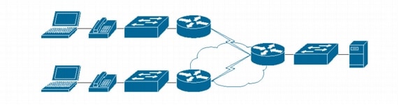
Figure 1. A Typical Hub-and-Spoke Centralized Cisco CallManager Topology
The following illustrates the operation of MCAST MOH from a centralized MCS to remote site phones. For simplicity, it is assumed that standard IP connectivity is available across a Cisco internetwork, that the IP telephony devices are not in an initial setup state and are set to autoconfigure, and that any traffic shaping shown is to support the MOH, whose source is the MCS. All network design diagrams, configuration, and "show" command output are taken from the Berkeley Group test network: Cisco 3620/2610 running IOS 12.2.6i (LD) Enterprise Plus, File Name:c3620-js-mz.122-6i.bin/c2600-js-mz.122-6i.bin IP.
This section follows a pathway from the IP handset through the LAN/WAN infrastructure toward the MCS/Cisco CallManager. On installation of an IP telephony handset, the MCS is configured to register the phone's MAC address and the firmware type (Cisco IP Phone 7960, for example) [ADMIN]. The handset has nonvolatile Flash memory, where it stores firmware images and user-defined preferences. The phone, once plugged into an 802.1af-compliant Cisco switch, runs a bootstrap that loads this image, initializing its software and hardware. The phone is physically connected to a switch port that has a VLAN membership configuration informing the phone that it is in the voice VLAN (in this example, vlan 16):
interface FastEthernet0/x
switchport access vlan 2
switchport trunk encapsulation dot1q
switchport trunk native vlan 2
switchport mode trunk
switchport voice vlan 16
interface Vlan16
ip address 10.212.224.4 255.255.240.0
ip pim sparse-dense-mode
ip igmp
The phone proceeds with a Dynamic Host Configuration Protocol (DHCP) request for an IP address; in this instance, a service provided by the Cisco CallManager. The phone broadcasts for a DHCP server, which, in this centralized MCS model, is passed by the switch to the site router. The router has an IP helper address statement (helper addresses facilitate connectivity by forwarding certain broadcasts to a target server; use of IP helper statements should be limited to ensure that broadcast traffic does not flood the enterprise wide-area circuit) that forwards broadcasts to the Cisco CallManager, and the phone will receive a DHCP IP address allocation. Within this allocation, DHCP scope Option 150 is set, which indicates to the phone the IP address of the server running the Trivial File Transfer Protocol (TFTP) service (TFTP is a User Datagram Protocol [UDP]-based form of the FTP service). The phone then pulls the device load via TFTP from the MCS. If the firmware version stated within the load does not match the phone's current version, it pulls the new one from the MCS. Once the new firmware is installed, the phone resets itself and re-enters the process. Having the latest firmware, it now pulls a CNF file (*.cnf.xml extension). For each phone that is manually configured on the Cisco CallManager, a separate CNF is created; this provides the communications details between the phone and MCS, such as:
• Ethernet port numbers
• Time zone information
• Directory/service URLs
• Cisco CallManager cluster information
The file is created with the device name of the phone. Phones always start with SEP, then the MAC address, unless changed in the Cisco CallManager. A typical file name is SEP000B5F7FFAA9.cnf.xml (autoregistration phones use the SEPDefault.cnf.xml file). The phone is now ready to participate in the IP telephony infrastructure.
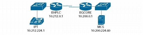
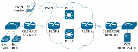
To ensure that a single media MOH stream is delivered, the LAN devices (including the edge router) through which data will pass must participate within the multicast environment. Figure 2 illustrates the Frame Relay environment discussed in this paper. The MCS server connects to a switch, which, in addition to any VLAN configuration, runs IP Multicast routing and Protocol-Independent Multicast (PIM) in sparse-dense mode, while the local router runs IP Multicast routing and PIM in sparse-dense mode along with Internet Group Management Protocol (IGMP), a Layer 3 communications protocol developed to enable internetworking devices to establish host memberships in particular multicast groups on a single network. This protocol allows a host to inform its local router, using the "Host Membership Reports" feature, that it wants to receive messages addressed to a specific multicast group [Hucaby, Boyle]. The router runs IP Multicast routing and IP PIM sparse-dense mode on any physical interface that must participate in multicast (PIM is in either sparse or dense mode, but the interface can be configured to forward sparse mode, dense mode, or both). In addition, IGMP snooping or Cisco Group Management Protocol is used on the Layer 2 switches to constrain the flooding of multicast and broadcast data from participating switches. The router also performs IP Precedence and access control lists (ACLs), shown below:
class-map match-all voip-rtp
match access-group 102
access-list 102 permit udp any any range 16384 32767
route-map Set-IP-QoS permit 20
match ip address 102
set ip precedence critical
Access-list 102 indicates that ports 16384 to 32767 have been allocated for UDP. Although 16383 appears frequently, the Cisco CallManager only uses even integers (Figure 3-Base Multicast Port number), so only 8191 ports are actually used. These ports, matched via the ACL to the route map, set the IP Precedence value in the Type of Service (ToS) field within the IP datagram. In this example, the value is set to critical (5). The classification range is 0-7, where 0 (the default) is the lowest and 7 is the highest priority, which allows for classification and prioritization of traffic. The router at the hub again runs IP Multicast routing and IP PIM sparse-dense mode on any physical interface that must participate in multicast, and also acts as a rendezvous point for the remote PIM routers, receiving from these routers the JOIN messages for the multicast tree. This indicates that PIM sparse mode uses an explicit request approach. PIM sparse mode is especially useful where you require more precise control, especially in relation to large volumes of IP Multicast traffic compared to the available bandwidth. PIM sparse mode is particularly scalable, because packets only go where needed, and the state is only created within the routers as needed. The cost of this extra control is additional complexity, as PIM sparse mode uses a special router called a rendezvous point to connect the multicast tree (flow source) to the router next to the recently joined receiver.
Figure 2. Frame Relay Internetwork
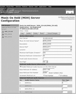
Many registration and configuration details have to be entered into a MCS, such as Cisco CallManager, to provide full VoIP services. This paper concentrates on the management details required to deliver MOH. These details are entered through an administration page (Figure 3), which must hold entries for at least:
• MOH server name <name>
• Device pool <name>
• Maximum half duple stream <integer>
• Maximum multicast connections <integer>
• Run flag <yes/no>
• Multicast audio services enabled <?>
• Base multicast IP address <IP address>
• Base port number <integer>
• Increment multicast on <port/IP> (IPMCAST recommends that Increment Multicast on IP Address is selected; this is subjective, dependent on the enterprise configuration of the location-based call admission control of the MOH MCAST server)
• Audio source <file name>
Figure 3. MOH Server Configuration
In addition to these configurations, a media resource group (MRG) must be configured. An MRG is a logical group of media resources available in a prioritized order. MRGs are ordered and contained within an MRG list (MRGL). The MRGL is allocated to the IP telephony phones and media gateways (typically an H.323 gateway, such as a router with a PSTN channelized ISDN30 module) via the "Device Pool" configuration on the Cisco CallManager. During call initiation, the MCS will set up the call through a process of dial mappings. Any buttons pressed on the phone create TCP signaling events interpreted by the MCS. For example, if a call between Extensions 1000 and 1200 is in progress and Extension 1000 (an IP phone) places Extension 1200 in "User Hold" ("Network Hold" is invoked when a user is placed in hold by another feature, such as call transfer), the Cisco CallManager signals the IP phone (Extension 1200) via the Skinny protocol to perform an IGMP join for the multicast MOH group if this phone is an IP phone, or informs the media gateway for non-IP phones. The IP phone (Extension 1200) or gateway signals the network that it wishes to receive the multicast stream associated with the MOH server configuration; PIM is used to forward this stream from the MOH server's first-hop router through the WAN or PSTN to Extension 1200. If another extension in the same branch office now places an internal call on hold, the same process is followed, but the local switch and router know via IGMP/PIM that an existing stream is already being forwarded, so a copy of the existing stream is forwarded from the local branch office switch. When the holding phone resumes the call, an "IGMP Leave" signal indicates that the multicast traffic is no longer required for that session. Hence, two privately addressed enterprise IP telephony systems with no public IP interface (but connected to the PSTN) can still interact at the voice level and would receive MOH in the same way a POTS phone would.
The multicast traffic across the Frame Relay permanent virtual circuit (PVC) operates at Layer 2. To conclude this section, the following command output is given from the lab network. This consisted of multiple remote routers connected by serial lines, encapsulated as Frame Relay, to a hub router. The hub router consisted of x physical interfaces and y virtual interfaces and was the rendezvous point toward which the remote sites sent their JOIN messages:
Multicast Source:
BGCORE.ROUTER# sh ip pim rp
Group: 239.255.255.254, RP: 10.200.0.1, v2, v1, next RP-reachable in 00:00:18
Group: 239.1.1.105, RP: 10.200.0.1, v2, v1, next RP-reachable in 00:01:13
Group: 239.1.1.100, RP: 10.200.0.1, v2, v1, next RP-reachable in 00:01:17
Group: 239.83.100.109, RP: 10.200.0.1, v2, v1, next RP-reachable in 00:00:54
Shown below are the results of the command show ip mroute [MROUTE] at the multicast destination, which displays the multicast route table and shows that the remote site router is participating in a multicast group for the MOH (239.1.1.105) configured in the Cisco CallManager's MOH server configuration.
BHPLC.ROUTER#show ip mroute
IP Multicast Routing Table
Flags*: D - Dense, C - Connected
Outgoing interface flags: H - Hardware switched
(*Some flags removed for simplicity)
Timers: Uptime/Expires
Interface state: Interface, Next-Hop or VCD, State/Mode
(*, 239.1.1.105), 7w0d/00:02:27, RP 10.200.0.1, flags: DC
The implementation of non-MCAST-aware MPLS nodes introduces an additional level of complexity to this process.
MCAST MOH DELIVERY VIA MPLS IP VPN INTERNETWORKS
MPLS VPNs [RFC2547, RFC3031] allow multiple customers using the same RFC 1918 address space, to interconnect their sites transparently through a service provider network. Each VPN appears to its users as a private network, separate from all other networks; within a VPN, each site can send IP packets to any other site in the same VPN. To achieve this, each VPN is associated with one or more VPN routing/forwarding instances (VRFs). A VRF consists of a separate IP routing table and derived Cisco Express Forwarding3 table for each VRF, together with a set of interfaces that use this forwarding table, thus preventing information being transmitted outside the VPN. This use of separate route tables allows the same IP addressing scheme to be used without duplicate address problems [MPLS]. The provider edge routers use Multiprotocol Border Gateway Protocol (MP-BGP) to distribute VPN routing information using the MP-BGP extended communities. Cisco Express Forwarding is a scalable, distributed, Layer 3 IP switching solution, and a critical component of the Cisco tag switching (MPLS) architecture.
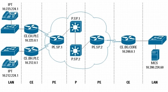
An MPLS infrastructure consists of three main devices4: the customer edge device (local-circuit termination and use of Layer 2 or Layer 3 MPLS; determines if the device is a router or a switch), the provider edge device and the provider device. Figure 4 shows a typical MPLS internetwork and the demarcation between the devices.
Note: MPLS networks are generally provided to the enterprise market as a wires-only service, whereby the enterprise manages the customer edge and injects traffic into the service-provider-managed core or as a complete managed service (CE2CE). In the CE2CE model, the enterprise would be required to negotiate with the service provider regarding the support of VoIP modules within the customer edge, as this could affect the service provider's SLA to the enterprise. In the event that a service provider is unwilling to support these modules, a customer premises equipment (CPE) device may need to be introduced.
Figure 4. MPLS Demarcation
The customer edge node is MPLS-unaware, and routes all traffic to the provider edge node or nodes via static routes or by participating in an Internal Gateway Protocol (IGP) with the provider edge. The customer edge router(s) can be configured with a default route to the provider edge (shown below) or can operate an IGP such as Routing Information Protocol (RIP).
Static default route example:
ip route 0.0.0.0 0.0.0.0 Serial0/0
IGP (RIP) example:
router rip
version 2
redistribute bgp 1 metric transparent
network 10.0.0.0
network 150.1.0.0
no auto-summary
!
As stated earlier, the provider edge nodes control the distribution of VPN routing information through the use of VPN route target communities:
ip vrf berkeleyHomes !Note 1
rd 1:20 !Note 2
route-target export 1:20 !Note 3
route-target import 1:20 !Note 3
Note:
1. Configures a VRF routing table
2. Creates routing and forwarding table
3. Creates a lit of import and/or export route target communities for the specific VRF
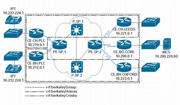
Figure 5 shows an example of separate VPNs terminated on a provider edge node. This can be done not only by service providers to achieve separation between customers, but also by the Berkeley Group to achieve separation between autonomous business units. VPNs can be terminated in several ways:
• Intranet VPN-Connects sites within an organization
• Managed network-A dedicated VPN is established by the service provider to manage customer edge routers
• Simple VPN-Every site can communicate with every other site
• Extranet VPN-Connects different organizations in a secure way
• Overlapping VPN-Some sites participate in more than one simple VPN
• Central services VPN-All sites can communicate with central servers, but not with each other
• Access VPN-VPDialN provides dialup access into the customer network
Figure 5. Intranet and Central Services VPNs
A central services site operating within multiple VPNs can be achieved by the provider edge importing multiple route targets from the required VRFs:
ip cef3
!
ip vrf berkeleyGroup
rd 1:30
route-target export 1:10
route-target import 1:10
route-target import 1:20
route-target import 1:30
!
ip vrf berkeleyHomes
rd 1:20
route-target export 1:20
route-target import 1:20
!
ip vrf berkeleyCrosby
rd 1:30
route-target export 1:30
route-target import 1:30
Having configured the VRF instances and the IGP, iBGP is used to distribute the VRF information between provider edge neighbors:
router bgp 1
no synchronization
bgp log-neighbor-changes
redistribute rip
neighbor 192.168.254.254 remote-as 1
neighbor 192.168.254.254 update-source Loopback0
neighbor 192.168.255.253 remote-as 1
neighbor 192.168.255.253 update-source Loopback0
neighbor 192.168.255.254 remote-as 1
neighbor 192.168.255.254 update-source Loopback0
no auto-summary
!
address-family ipv4 vrf berkeleyGroup
redistribute connected
redistribute rip
no auto-summary
no synchronization
exit-address-family
!
address-family ipv4 vrf berkeleyHomes
redistribute connected
redistribute rip
no auto-summary
no synchronization
exit-address-family
!
address-family ipv4 vrf berkeleyCrosby
redistribute connected
redistribute rip
no auto-summary
no synchronization
exit-address-family
!
address-family vpnv4
neighbor 192.168.254.254 activate
neighbor 192.168.254.254 send-community extended
neighbor 192.168.255.253 activate
neighbor 192.168.255.253 send-community extended
neighbor 192.168.255.254 activate
neighbor 192.168.255.254 send-community extended
no auto-summary
exit-address-family
!
interface Serial1/0
description serial to P.SP.2
ip address 192.168.20.2 255.255.255.0
ip router isis
tag-switching ip
no fair-queue
serial restart-delay 0
!
interface Serial1/1
description serial to CE.CH.EDGBASTON
ip vrf forwarding berkeleyCrosby
ip address 150.1.40.1 255.255.255.0
serial restart-delay 0
!
interface Serial1/2
description serial to CE.BH.PLC
ip vrf forwarding berkeleyHomes
ip address 150.1.50.1 255.255.255.0
serial restart-delay 0
!
interface Serial1/3
description serial to CE.BG.CORE
ip vrf forwarding berkeleyGroup
ip address 150.1.10.1 255.255.255.0
serial restart-delay 0
!
Finally, to maintain a connection through the provider nodes, the provider edges interact through a protocol such as Intermediate System-to-Intermediate System (ISIS):
router isis
net 49.0002.0000.0000.0002.00
is-type level-1
metric-style wide
The output below shows the results of the command show ip route vrf vrf-name from the connected provider edge node. This displays the IP routing table associated with the central services site berkeleygroup(s) VRF and can be seen to be importing IP routes for both berkeleyHomes and berkeleyCrosby VRFs:
PE.SP.1#show ip route vrf berkeleyGroup
Codes: C - connected, S - static, I - IGRP, R - RIP, M - mobile, B - BGP, D - EIGRP, EX - EIGRP external, O - OSPF, IA - OSPF inter area, N1 - OSPF NSSA external type 1, N2 - OSPF NSSA external type 2, E1 - OSPF external type 1, E2 - OSPF external type 2, E - EGP, i - IS-IS, L1 - IS-IS level-1, L2 - IS-IS level-2, ia - IS-IS inter area, * - candidate default, U - per-user static route, o - ODR, P - periodic downloaded static route
Gateway of last resort is not set
172.16.0.0/30 is subnetted, 1 subnets
B 172.16.1.0 [200/1] via 192.168.254.253, 00:44:59
10.0.0.0/8 is variably subnetted, 9 subnets, 2 masks
B 10.200.0.0/20 [200/1] via 192.168.254.253, 00:44:59
B 10.219.0.0/20 [200/1] via 192.168.254.253, 00:43:29
B 10.221.0.0/20
[20/1] via 150.1.30.2 (berkeleyCrosby), 00:44:59, Serial0/1
B 10.212.254.1/32 [200/1] via 192.168.254.253, 00:44:59
B 10.223.254.1/32
[20/1] via 150.1.20.2 (berkeleyHomes), 00:44:59, Serial0/2
B 10.223.0.0/20
[20/1] via 150.1.20.2 (berkeleyHomes), 00:45:00, Serial0/2
B 10.221.254.1/32
[20/1] via 150.1.30.2 (berkeleyCrosby), 00:45:00, Serial0/1
B 10.219.254.1/32 [200/1] via 192.168.254.253, 00:43:30
B 10.200.254.1/32 [200/1] via 192.168.254.253, 00:45:01
150.1.0.0/24 is subnetted, 5 subnets
B 150.1.20.0 is directly connected, 00:44:46, Serial0/2
B 150.1.30.0 is directly connected, 00:44:46, Serial0/1
B 150.1.10.0 [200/0] via 192.168.254.253, 00:45:01
B 150.1.50.0 [200/0] via 192.168.254.253, 00:45:01
B 150.1.40.0 [200/0] via 192.168.254.253, 00:45:01
The following output shows the results of the command show ip route from the connected multicast source customer edge node. This displays the IP routing table on this customer edge router and shows that this router has routes to all other sites redistributed by the provider edge iBGP into the customer edge IGP (RIP):
CE.BG.CORE#sh ip route
Codes: C - connected, S - static, I - IGRP, R - RIP, M - mobile, B - BGP, D - EIGRP, EX - EIGRP external, O - OSPF, IA - OSPF inter area, N1 - OSPF NSSA external type 1, N2 - OSPF NSSA external type 2, E1 - OSPF external type 1, E2 - OSPF external type 2, E - EGP, i - IS-IS, L1 - IS-IS level-1, L2 - IS-IS level-2, ia - IS-IS inter area
* - candidate default, U - per-user static route, o - ODR
P - periodic downloaded static route
Gateway of last resort is 0.0.0.0 to network 0.0.0.0
172.16.0.0/30 is subnetted, 1 subnets
C 172.16.1.0 is directly connected, Tunnel0
10.0.0.0/8 is variably subnetted, 9 subnets, 2 masks
C 10.200.0.0/20 is directly connected, Ethernet0/0
R 10.219.0.0/20 [120/1] via 150.1.10.1, 00:00:01, Serial0/0
R 10.221.0.0/20 [120/1] via 150.1.10.1, 00:00:01, Serial0/0
R 10.212.254.1/32 [120/1] via 150.1.10.1, 00:00:01, Serial0/0
R 10.223.254.1/32 [120/1] via 150.1.10.1, 00:00:01, Serial0/0
R 10.223.0.0/20 [120/1] via 150.1.10.1, 00:00:01, Serial0/0
R 10.221.254.1/32 [120/1] via 150.1.10.1, 00:00:01, Serial0/0
R 10.219.254.1/32 [120/1] via 150.1.10.1, 00:00:01, Serial0/0
C 10.200.254.1/32 is directly connected, Loopback0
150.1.0.0/24 is subnetted, 5 subnets
R 150.1.20.0 [120/1] via 150.1.10.1, 00:00:02, Serial0/0
R 150.1.30.0 [120/1] via 150.1.10.1, 00:00:02, Serial0/0
C 150.1.10.0 is directly connected, Serial0/0
R 150.1.50.0 [120/1] via 150.1.10.1, 00:00:02, Serial0/0
R 150.1.40.0 [120/1] via 150.1.10.1, 00:00:02, Serial0/0
S* 0.0.0.0/0 is directly connected, Serial0/0 is directly connected
This proves that we have Layer 3 connectivity from end to end across the service provider's core MPLS network. We can now look to support the MCAST MOH. This will be achieved through the configuration of the multicast services, as before, and the building of GRE tunnels.
A GRE [RFC2784] tunnel is a logical router interface that forwards IP (or other network protocols such as Open Systems Interconnection [OSI] network layer, XNS, VINES, DECnet (Phase IV), Apollo Domain, Ethertalk (Appletalk), and Novell) traffic.
Figure 6. MOH MCAST over MPLS-Based GRE Tunnels
The switch and router configuration for multicast is the same as for a circuit switched environment; the Layer 3 multicast is now passed through the GRE tunnel, which is built with the following configuration on the customer edge router (or CPE):
Multicast Source:
CE.BG.CORE#
!
ip multicast-routing
!
interface Loopback0
description management interface
ip address 10.200.254.1 255.255.255.255
no ip directed-broadcast
!
interface Tunnel0
description BHPLC GRE tunnel for MCAST MOH
ip address 172.16.1.1 255.255.255.252
no ip directed-broadcast
ip pim sparse-dense-mode
tunnel source Loopback0
tunnel destination 10.212.254.1
!
ip mroute 10.212.0.0 255.255.0.0 Tunnel0
ip mroute 10.212.254.1 255.255.255.255 Tunnel0
CE.BG.CORE# sh ip route
Gateway of last resort is 0.0.0.0 to network 0.0.0.0
172.16.0.0/30 is subnetted, 1 subnets
C 172.16.1.0 is directly connected, Tunnel0
Multicast Destination:
CE.BH.PLC#
!
ip multicast-routing
!
interface Loopback0
description management interface
ip address 10.212.254.1 255.255.255.255
!
interface Tunnel0
description GRE tunnel for MCAST MOH
ip address 172.16.1.2 255.255.255.252
ip pim sparse-dense-mode
tunnel source Loopback0
tunnel destination 10.200.254.1
!
ip mroute 10.200.0.0 255.255.0.0 Tunnel0
ip mroute 10.200.254.1 255.255.255.255 Tunnel0
From the multicast source, all multicast traffic for BHPLC is sent to the GRE tunnel. If additional remote sites require MCAST MOH, additional tunnels can be created to support them. This creates a hub-and-spoke internetwork, with the central site that provides the multicast source acting as the hub.
To test the GRE tunnels, standard show ip route commands and Internet Control Message Protocol (ICMP) ping can be used; however, specialized mroute commands such as show ip mroute can be run [MROUTE]. Although the test lab benefited from a Cisco CallManager and IP telephony handsets, initial GRE configuration was tested with a multicast traffic generator/analyzer. The results of the IP Multicast Routing Table are shown below:
CE.BG.CORE#sh ip mroute
IP Multicast Routing Table
Flags: D - Dense, S - Sparse, C - Connected, L - Local, P - Pruned, R - RP-bit set, F - Register flag, T - SPT-bit set, J - Join SPT, X - Proxy Join Timer Running
Outgoing interface flags: H - Hardware switched
Timers: Uptime/Expires
Interface state: Interface, Next-Hop or VCD, State/Mode
(*, 239.255.255.250), 00:02:10/00:02:51, RP 0.0.0.0, flags: DJC
The following command enables the enterprise network manager to see information such as source, destination, and joined interface for multicast traffic:
Although the configuration of the GRE tunnels is relatively simple, troubleshooting and ongoing network management support should not be overlooked. One of the major obstacles to overcome in early GRE deployment is the issue of recursive routing or GRE tunnel flapping [TUNFLAP]. This is generally a misconfiguration of the tunnel router, which results in the router attempting to route to the tunnel destination via the tunnel interface itself, or temporary instability caused by route flapping elsewhere within the network:
01:11:39: %LINEPROTO-5-UPDOWN: Line protocol on Interface Tunnel0, changed state to up
01:11:48: %TUN-5-RECURDOWN: Tunnel0 temporarily disabled due to recursive routing
01:11:49: %LINEPROTO-5-UPDOWN: Line protocol on Interface Tunnel0, changed state to down
01:12:49: %LINEPROTO-5-UPDOWN: Line protocol on Interface Tunnel0, changed state to up
01:12:58: %TUN-5-RECURDOWN: Tunnel0 temporarily disabled due to recursive routing
01:12:59: %LINEPROTO-5-UPDOWN: Line protocol on Interface Tunnel0, changed state to down
Another major issue with GRE that must be considered at the initial design stage is scalability. Each site that requires MCAST MOH requires its own GRE tunnel and tunnel interface, adding to configuration and support complexity.
FUTURE TECHNOLOGIES AND SOLUTIONS
Much work is being undertaken within the industry for future support of multicast over MPLS. This paper covers software-based and hardware-based support.
Software-Based
Cisco mVRF/mVPN
Service providers generally want to ensure transparency between customer multicast streams and core capability. Multicast VPN (mVPN) is a high-level terminology for technologies, such as mVRF, that essentially permit this privacy (e.g. ships in the night implementation, but the service provider is still required to run multicast in the core). Cisco has released the mVPN solution (based on draft-rosen-vpn-mcast.txt, currently draft-rosen-vpn-mcast-07.txt [ROSEN]), supported since Cisco IOS® Release 12.0(23)S, that enables this capability. At each provider edge, the service provider creates a Multicast Tunnel Interface (MTI) and Multicast VPN VRF for each customer. The MTI encapsulates customers' multicast packets within its own multicast packet with a destination group that is unique for a particular customer, and in which all provider edges (that are aware of that particular customer) participate. The service provider core does not need to know the multicast groups of each customer; instead, they know only the necessary information for transporting the encapsulated multicast packets [Brunetto], [Morrow], [Bunn]. Many MPLS-based Cisco Powered networks have now implemented this technology [Brunetto].
Hardware-Based
"GRE-in-a-Box"
The MPLS Forum's MPLS User Group (MUG) is currently discussing the subject of multicast support over MPLS. One of the areas to be promoted is "GRE-in-a-Box." Liaising with vendors such as Riverstone Networks, MUG members will discuss the feasibility of an affordable hardware solution, which, with minimum configuration via a Web-based interface, will support enterprise GRE tunnels.
SUMMARY
Businesses adopt technologies that provide competitive advantage and the use of convergence to deliver multimedia applications. Voice, in particular, has sparked massive interest within enterprises. During any review of convergence benefits, the enterprise network manager should consider the role of its department within the company, as well as the company's mission. This process was undertaken at Berkeley; from this review, the decision was made to selectively outsource WAN management to a third-party service provider, which enabled Berkeley, internally, to concentrate on the delivery of business systems. While initially reluctant to outsource, it has paid dividends in reducing the internal reactive troubleshooting (through good network design while implementing the new network, and through the service provider network support itself) and has enabled the team to concentrate on research and development of new systems and technologies that will enable Berkeley to provide real business benefits to the group. If an enterprise network management team decides that selective outsourcing is an approach that matches its business model, and if during the convergence program the team seeks to benefit from the use of MPLS-based technologies, the team should make sure that all of the capabilities that their current infrastructure provides can be delivered over the new platform, as well as understand what additional changes to delivery or management need to be incorporated. This is one of the most important times the enterprise network has faced for many years. We can all learn and benefit from the experiences we face.
[Brunetto] Brunetto, A., Error! Hyperlink reference not valid.(2003), MOH Over MPLS, December 2003. [Newsgroup Discussion List] <mpls-ops@mplsrc.com> [Accessed 5th December 2003]
[Bunn] Bunn, B., (bbunn@cisco.com) (26th November 2003), MOH Over MPLS, Personal e-mail to Doug Legge (doug.legge@berkeleygroup.co.uk)
[Hucaby, Boyle] Hucaby, D., Boyle, T. (2001). CCNP Switching, Exam Certification Guide. Indianapolis, Cisco Press.
[Morrow] Morrow, M., (mmorrow@cisco.com) (4th December 2003), MOH Over MPLS, Personal e-mail to Doug Legge (doug.legge@berkeleygroup.co.uk)
[MOS] Information about a New Method for Deriving the Transmission Rating Factor R from Mos in Closed Form, ITU - Telecommunication Standardization Sector, Temporary Document XX-E WP 2/12, 2003 [Internet], Technical University of Berlin, http://www.tkn.tu-berlin.de/publications/papers/MOS_R2.pdf
[Accessed 5th December 2003]
[RFC3353] Network Working Group, Request for Comments: 3353, Overview of IP Multicast in a Multiprotocol Label Switching (MPLS) Environment, (2002) [Internet], IETF, http://www.ietf.org/rfc/rfc3353.txt?number=3353
[Accessed 5th December 2003]
[TUNFLAP] Cisco Troubleshooting the "%TUN_5_RECURDOWN" Error Message and Flapping EIGRP/OSPF/BGP Neighbors Over a GRE Tunnel, (2002) [Internet], IETF, http://www.cisco.com/warp/public/105/gre_flap.pdf
[Accessed 5th December 2003]
[an error occurred while processing this directive]