Cisco 7200 Series Router Architecture
Available Languages
Contents
Introduction
This document is provides overview of the hardware and software architecture of the Cisco 720x Series Routers.
Prerequisites
Requirements
There are no specific requirements for this document.
Components Used
This document is not restricted to specific software versions, and is based on the Cisco 7200 Series Routers.
The information in this document was created from the devices in a specific lab environment. All of the devices used in this document started with a cleared (default) configuration. If your network is live, make sure that you understand the potential impact of any command.
Conventions
For more information on document conventions, see the Cisco Technical Tips Conventions.
Hardware Architecture
Chassis Overview
The 7200 Series Router chassis consists of the 2-slot Cisco 7202, the 4-slot Cisco 7204 and Cisco 7204VXR, and the 6-slot Cisco 7206 and Cisco 7206VXR:
-
7202: A two-slot chassis that supports only these Network Processing Engines (NPEs):
-
NPE-100
-
NPE-150
-
NPE-200
-
-
7204: A 4-slot chassis with the legacy midplane.
-
7206: A 6-slot chassis with the legacy midplane.
-
7204VXR: A 4-slot chassis with the VXR midplane.
-
7206VXR: A 6-slot chassis with the VXR midplane.
The 7200 Series hardware architecture varies from model to model, and depends upon the combination of chassis and NPE, but it generally can be separated into two major designs. This document focusses on these two main designs:
-
Routers with the original midplane, and an early NPE (NPE-100, NPE-150, NPE-200).
-
Routers with the VXR midplane, and a later NPE (NPE-175, NPE-225, NPE-300, NPE-400, NPE-G1, and so on)
The VXR chassis provides a 1 Gbps midplane when used with the NPE-300, NPE-400, or NPE-G1. In addition, the VXR midplane includes a Multiservice Interchange (MIX). MIX supports switching of DS0 time slots through MIX interconnects across the midplane to each port adapter slot. The midplane and the MIX also support distribution of clocking between channelized interfaces to support voice and other constant-bit-rate applications. The VXR midplane provides two full-duplex 8.192 Mbps time division multiplexing (TDM) streams between each port adapter slot and the MIX, which has the capacity to switch DS0s on all 12 8.192 Mbps streams. Each stream can support up to 128 DS0 channels.
Cisco 7200 VXR routers also support the Network Service Engine NSE-1, which consists of two modular boards: the processor engine board and the network controller board. The processor board is based on the NPE-300 architecture. The network controller board hosts the Parallel eXpress Forwarding (PXF) processor, which works with the routing processor to provide accelerated packet switching, and accelerated IP Layer 3 feature processing.
Network Processing Engines - Network Services Engine
The NPE contains the main memory, the CPU, the Peripheral Component Interconnect (PCI) memory (static random-access memory - SRAM), except on the NPE-100 which uses dynamic RAM (DRAM)), and the control circuitry for the PCI buses. The network processing engines consist of the following components:
-
A reduced instruction set computing (RISC) microprocessor. Table 1 lists the microprocessors and their internal clock speeds for various NPEs.
Table 1 – RISC Microprocessors for various NPEsNetwork Processing Engine Microprocessor Internal Clock Speed NPE-100 and NPE-150 R4700 150 MHz NPE-175 RM5270 200 MHz NPE-200 R5000 200MHz NPE-225 RM5271 262 MHz NPE-300 RM7000 262 MHz NPE- 400 RM7000 350 MHz NPE-G1 BCM1250 700 MHz NSE-1 RM7000 262 MHz -
System Controller
-
The NPE-100, NPE-150, and NPE-200 have a system controller that uses direct memory access (DMA) to transfer data between DRAM and packet SRAM on the network processing engine.
-
The NPE-175 and NPE-225 have one system controller that provides processor access to the two midplane and single input/output (I/O) controller PCI buses. The system controller also allows port adapters on either of the two midplane PCI buses to access SDRAM
-
The NPE-300 has two system controllers that provide processor access to the two midplane and single I/O controller PCI buses. The system controller also allows port adapters on either of the two midplane PCI buses to access SDRAM.
-
The NPE-400 has one system controller that provides system access.
-
The NPE-G1 BCM1250 also maintains and executes the system management functions for the Cisco 7200 VXR routers, and holds the system memory and environmental monitoring functions.
-
The NSE-1 has one system controller that provides processor access to the midplane and single I/O controller PCI buses. The system controller also allows port adapters on either of the two midplane PCI buses to access SDRAM.
-
-
Memory modules that can be upgraded
-
The NPE-100, NPE-150, and NPE-200 use DRAM to store routing tables, network accounting applications, packets of information in preparation for process switching, and packet buffering for SRAM overflow (except in the NPE-100, which contains no packet SRAM). The standard configuration is 32 MB, with up to 128 MB available through single in-line memory module (SIMM) upgrades.
-
The NPE-175 and NPE-225 use SDRAM to provide code, data, and packet storage.
-
The NPE-300 uses SDRAM to store all packets received or sent from network interfaces. The SDRAM also stores routing tables and network accounting applications. Two independent SDRAM memory arrays in the system allow concurrent access by port adapters and the processor. The NPE-300 has a fixed configuration caveat with the first 32MB dimm. See Table 3-2 at NPE-300 and NPE-400 Overview for more information.
-
The NPE-400 uses SDRAM to store all packets received or sent from network interfaces. The SDRAM memory array in the system allows concurrent access by port adapters and the processor.
-
The NSE-1 uses SDRAM to provide code, data, and packet storage.
-
The NPE-G1 uses SDRAM to store all packets received or sent from network interfaces. The SDRAM also stores routing tables and network accounting applications. Two independent SDRAM memory arrays in the system allow concurrent access by port adapters and the processor.
-
-
Packet SRAM to store packets of information in preparation for fast switching
-
The NPE-150 has 1 MB of SRAM and the NPE-200 has 4 MB of SRAM. No other network processing engine or network services engine has SRAM.
-
-
Cache memory
-
The NPE-100, NPE-150, and NPE-200 have unified cache that functions as the secondary cache for the microprocessor (the primary cache is within the microprocessor).
-
The NPE-175 and NPE-225 have two levels of cache: a primary cache that is internal to the processor and a secondary, 2-MB external cache that provides additional high-speed storage for data and instructions.
-
The NPE-300 has three levels of cache: a primary and a secondary cache that are internal to the microprocessor, and a tertiary, 2-MB external cache that provides additional high-speed storage for data and instructions.
-
The NPE-400 has three levels of cache: a primary and a secondary cache that are internal to the microprocessor, and a tertiary 4-MB external cache that provides additional high-speed storage for data and instructions.
-
The NSE-1 has three levels of cache: a primary and a secondary unified cache that are internal to the microprocessor, and a tertiary, 2-MB external cache.
-
The NPE-G1 has two levels of cache: a primary and a secondary cache that are internal to the microprocessor. The secondary unified cache is used for data and instruction.
-
-
Two environmental sensors to monitor the cooling air as it leaves the chassis.
-
Boot ROM to store sufficient code to boot the Cisco IOS® software; the NPE-175, NPE-200, NPE-225, NPE-300, NPE-400, NPE-G1, and NSE-1 have boot ROM.
The Network Service Engine (NSE-1) delivers wire rate OC3 throughput while running concurrent high-touch WAN edge services. The underlying design leverages NPE-300 technology enhanced by a process intensive microcode engine called Parallel Express Forwarding (PXF) engine. This unique dual processing architecture offers a tremendous performance increase for process-hungry, intelligent network services. The Route/Switch Processor offloads complex Layer 4 through Layer 7 high-touch services to the PXF processor, and sustains wire rate performance.
For additional information, see:
I/O Board
The I/O controller shares the system memory functions and the environmental monitoring functions for the Cisco 7200 router with the network processing engine. It contains these components:
-
One or two autosensing Ethernet/Fast Ethernet ports or 1 Gigabit Ethernet and 1 Ethernet port, based on the I/O controller type.
-
Dual channels for local console and auxiliary ports.
-
Flash memory to store the boot helper image as well as other data (such as crashinfo files).
-
Two PC Card slots for Flash Disks or Flash memory cards, which contain the default Cisco IOS software image.
-
Boot ROM to store sufficient code to boot the Cisco IOS software (the C7200-I/O-2FE/E does not have a boot ROM component).
-
Two environmental sensors to monitor the cooling air as it enters and leaves the Cisco 7200 chassis.
-
Nonvolatile random-access memory (NVRAM) to store the system configuration and environmental monitoring logs.
I/O Controller Descriptions
Table 2 – I/O Controllers and Their Descriptions| Product Number | Description |
|---|---|
| C7200-I/O-GE+E | One Gigabit Ethernet and one Ethernet port; equipped with a GBIC receptacle for 1000 megabits per second (Mbps) operation and an RJ-45 receptacle for 10-Mbps operation |
| C7200-I/O-2FE/E | Two autosensing Ethernet/Fast Ethernet ports; equipped with two RJ-45 receptacles for 10/100-Mbps operation. |
| C7200-I/O-FE1 | One Fast Ethernet port; equipped with an MII receptacle and an RJ-45 receptacle for use at 100 Mbps full-duplex or half-duplex operation. Only one receptacle can be configured for use at a time. |
| C7200-I/O | Has no Fast Ethernet port. |
| C7200-I/O-FE-MII2 | One Fast Ethernet port; equipped with a single MII receptacle. |
1 The Product Number C7200-I/O-FE does not specify MII because both an MII and an RJ-45 receptacle are included.
2 The I/O controller with the Product Number C7200-I/O-FE-MII has a single MII Fast Ethernet receptacle only. Although still supported by Cisco Systems, this I/O controller with a single MII receptacle has not been available for order since May 1998.
You can also identify your I/O controller model from a terminal. To do so, use the show diag slot 0 command.
The NPE-G1 is the first network processing engine for the Cisco 7200 VXR routers to provide the functionality of both a network processing engine and I/O controller. While its design provides I/O controller functionality, it can also work with any I/O controller supported in the Cisco 7200 VXR. When you install an I/O controller in a chassis with the NPE-G1, the console and auxiliary ports on the I/O controller are activated. In addition, the console and auxiliary ports on board the NPE-G1 are automatically disabled. However, you can still use the Flash disk slots and Ethernet ports on both the NPE-G1 and I/O controller when both cards are installed.
Note: I/O controllers are not hot-swappable. Before you insert the I/O controller, switch off the power.
For additional information, see:
Port Adapters (PAs)
These are modular interface controllers that contain circuitry to transmit and receive packets on the physical media. These are the same port adapters used on the Versatile Interface Processor (VIP) with the Cisco 7500 Series Router. Both platforms support most port adapters, but there are some exceptions. Some PAs that require the time division multiplexing (TDM) switch are supported only on the VXR midplane.
The port adapters installed in the Cisco 7200 routers support Online Insertion and Removal (OIR). They are hot-swappable.
Cisco 7200 Series Routers have a data-carrying capacity, referred to as bandwidth, that affects the port adapter distribution in the chassis, as well as the number and types of port adapters you can install. Port adapters must be evenly distributed by bandwidth between PCI bus mb1 (PA slots 0, 1, 3, and 5) and PCI bus mb2 (PA slots 2, 4, 6).
Cisco 7200 or Cisco 7200 VXR routers with a network processing engine (NPE) NPE-100, NPE-150, NPE-175, NPE-200, or NPE-225, use a high-, medium-, or low-bandwidth designation to determine port adapter distribution and configuration.
Cisco 7200 VXR routers with an NPE-300, NPE-400, or an NSE-1 use bandwidth points to determine port adapter distribution and configuration instead of high-, medium-, or low-bandwidth designations. Bandwidth points are an assigned value related to bandwidth; however, the value is adjusted based on how efficiently the hardware uses the PCI bus.
Note: You can use a Cisco 7200 Series Router with a port adapter configuration that exceeds the guidelines. However, to prevent irregularities while the router is in use, we strongly recommend that you restrict the port adapter types installed in the router, according to the guidelines listed in the links below. Additionally, your port adapter configuration must be within these guidelines before the Cisco Technical Assistance Center will troubleshoot anomalies that occur in your Cisco 7200 Series Router. Port adapters are hot-swappable..
Additional information can be found here:
-
What Causes %PLATFORM-3-PACONFIG and %C7200-3-PACONFIG Error Messages?
-
Cisco 7200 Series Port Adapter Hardware Configuration Guidelines
Note: The release of the new Cisco 7200 VXR router requires certain port adapter updates for forward compatibility. This requirement is due to the new and higher-speed Peripheral Component Interconnect (PCI) midplane in the Cisco 7200 VXR router. Only port adapters used in Cisco 7200 VXR routers require this update. Since all port adapters cannot be upgraded, some port adapters are not supported in Cisco 7200 VXR routers. For details, see Field Notice: Port Adapter Compatibility for Cisco 7200 VXR Routers.
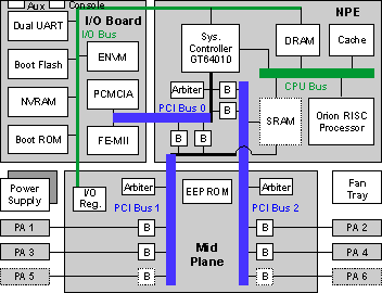
Block Diagram
Memory Details
The 7200 Series Router uses DRAM, SDRAM, and SRAM memory on the NPE in various combinations based on the model. The available memory is divided into three memory pools: the processor pool, the I/O pool, and the PCI pool (I/O-2 on NPE-300).
Here are some show memory command output examples that use a Cisco 7206 (NPE150) processor (revision B) with 43008K/6144K bytes of memory:
legacy_7206#show memory
               Head   Total(b)    Used(b)    Free(b)  Lowest(b) Largest(b)
Processor  61A08FE0   16740384   10070412    6669972    6502744    6596068
      I/O   2A00000    6291456    1482392    4809064    4517540    4809020
      PCI  4B000000    1048576     648440     400136     400136     400092

cisco 7206VXR (NPE300) processor (revision B) with 122880K/40960K bytes of memory

7206VXR#show memory
                Head    Total(b)     Used(b)     Free(b)   Lowest(b)  Largest(b)
Processor   6192B280    99437952    27769836    71668116    70358432    70358428
      I/O   20000000    33554440     4626776    28927664    28927664    28927612
    I/O-2    7800000     8388616     2140184     6248432     6248432     6248380
-
Processor memory: This pool is used to store the Cisco IOS software code, the routing tables, and the system buffers. It is allocated from the DRAM on the NPE-100, NPE-150, and the NPE-200; the SDRAM region on the NPE-175 and NPE-225; and SDRAM bank 1 on the NPE-300.
-
I/O memory: This pool is used for particle pools. Both the interface private pools and the public particle pool are allocated from this memory. The size of this memory depends on the type of NPE. The NPE-150 and the NPE-200 both have a fixed amount of SRAM that is used for a form of Input/Output (I/O) memory: 1 MB for the NPE-150 and 4 MBs for the NPE-200. The NPE-300 uses its SDRAM bank 0 which is fixed at 32 MB.
-
PCI memory: This small pool is mainly used for interface receive and transmit rings. It is sometimes used to allocate private interface particle pools for high-speed interfaces. On NPE-175, NPE-225, and NPE-300 systems, this pool is created in SDRAM. On the NPE-150 and NPE-200, it is created entirely on SRAM.
For detailed information about the location and memory table specifications, see Memory Location and Specifications. From this link, you can also find some memory-related guidelines and restrictions classified by NPE/NSE.
Another helpful link is Memory Replacement Instructions for the NPE or NSE and I/O Controller.
Boot Sequence
During the boot process, observe the system LEDs. The LEDs on most of the port adapters go on and off in an irregular sequence. Some may go on, go off, and go on again for a short time. On the I/O controller, the I/O power OK LED comes on immediately.
Observe the initialization process. When the system boot is complete (a few seconds), the network processing engine or network services engine begins to initialize the port adapters and the I/O controller. During this initialization, the LEDs on each port adapter behave differently (most flash on and off).
The enabled LED on each port adapter goes on when initialization is completed, and the console screen displays a script and system banner similar to this:
Cisco Internetwork Operating System Software
IOS (tm) 7200 Software (C7200-IK8S-M), Version 12.2(10b),
RELEASE SOFTWARE (fc1)
Copyright (c) 1986-2002 by cisco Systems, Inc.
Compiled Fri 12-Jul-02 07:47 by xxxxx
Image text-base: 0x60008940, data-base: 0x613D4000
When you start up the router for the first time, the system automatically enters the setup command facility, which determines which port adapters are installed and prompts you to provide configuration information for each one. On the console terminal, after the system displays the system banner and hardware configuration, you see this System Configuration Dialog prompt:
--- System Configuration Dialog ---

Would you like to enter the initial configuration dialog? [yes/no]:
If the system does not complete each of the steps in the startup procedure, see Troubleshooting the Installation for troubleshooting tips and procedures.
Packet Switching
The Cisco 7200 Series supports process switching, fast switching, and Cisco Express Forwarding (CEF), but does not support any form of distributed switching. The main CPU in the NPE performs all the switching tasks.
The description in this section is based on the book Inside Cisco IOS software Architecture, Cisco Press.1
1 - Packet Receive Stage
These steps illustrate what occurs when a packet is received:
Step 1: The packet is copied from the media into a series of particles linked to the receive ring of the interface. The particles can reside in either I/O memory or PCI memory, based on the media speed of the interface, and the platform.
Step 2: The interface raises a receive interrupt to the CPU.
Step 3: Cisco IOS software acknowledges the interrupt and begins to attempt the allocation of particles to replace the ones filled on the receive ring of the interface. Cisco IOS software checks the private pool of the interface first, and then checks the public normal pool if there is none in the private pool. If sufficient particles do not exist to replenish the receive ring, the packet is dropped (the particles of the packet on the receive ring are flushed), and the "no buffer" counter is incremented.
Cisco IOS software also throttles the interface in this case. When an interface is throttled on the 7200, all received packets are ignored until the interface is unthrottled. Cisco IOS software unthrottles the interface after the depleted particle pool is replenished with free particles.
Step 4: Cisco IOS software links the particles of the packet in the receive ring together, and then links them to a particle buffer header. It then links them to the ring in place of the packet's particles in order to replenish the receive ring with the newly allocated particles.
2 - Packet Switching Stage
Now that the packet is in particles, Cisco IOS software switches the packet. The steps below describe this process:
Step 5: The switching code first checks the route cache (fast or CEF) to see if it can fast switch the packet. If the packet can be switched during the interrupt, it skips to Step 6. Otherwise, it continues to prepare the packet for process switching.
-
5.1: The packet is coalesced into a contiguous buffer (system buffer). If no free system buffer exists to accept the packet, it is dropped, and the "no buffer" counter is incremented, as indicated in the output of the show interfaces command:
Router#show interfaces
Ethernet2/1 is up, line protocol is up
....
  Output queue 0/40, 0 drops; input queue 0/75, 0 drops
  5 minute input rate 5000 bits/sec, 11 packets/sec
  5 minute output rate 0 bits/sec, 0 packets/sec
     1903171 packets input, 114715570 bytes, 1 no buffer
     Received 1901319 broadcasts,  0 runts, 0 giants, 1 throttles
....
If Cisco IOS software cannot allocate a system buffer to coalesce a particle buffer, it also throttles the interface and increments the "throttles" counter, as indicated in the show interface command output example above. All input traffic is ignored while an interface is throttled. The interface remains throttled until Cisco IOS software has free system buffers available for the interface.
-
5.2: When the packet is coalesced, it is queued for process switching, and the process that handles this type of packet is scheduled to run. The receive interrupt is then dismissed.
-
5.3: Assume this is an IP packet. When the IP Input process runs, it consults the routing table and discovers the outbound interface. It consults the tables associated with the outbound interface and locates the MAC header that needs to be placed on the packet.
-
5.4: After the packet has been switched successfully, it is copied into the output queue for the outbound interface.
-
5.5: From here, Cisco IOS software proceeds to the transmit stage.
Step 6: Cisco IOS software switching code (fast or CEF) rewrites the MAC header in the packet for its destination. If the new MAC header is larger than the original header, Cisco IOS software allocates a new particle from the F/S pool and inserts it at the start of the chain of particles to hold the larger header.
3 - Packet Transmit Stage: Fast Switching and CEF
Now you have a successfully switched packet, with its MAC header rewritten. The packet transmit stage operates differently, based on whether Cisco IOS software fast switches the packet (fast or CEF), or process switches the packet. The following sections cover the packet transmit stage in the fast and process switching environments for Cisco 7200 Series Routers.
These steps describe the packet transmit stage in a fast switching environment:
Step 7: Cisco IOS software first checks the output queue of the interface. If the output queue is not empty or the transmit ring of the interface is full, Cisco IOS software queues the packet on the output queue, and dismisses the receive interrupt. The packet eventually gets transmitted either when another process-switched packet arrives, or when the interface issues a transmit interrupt. If the output queue is empty, and the transmit ring has room, Cisco IOS software continues to Step 8.
Step 8: Cisco IOS software links each of the particles of the packet to the transmit ring of the interface, and dismisses the receive interrupt.
Step 9: The interface media controller polls its transmit ring, and detects a new packet to be transmitted.
Step 10: The interface media controller copies the packet from its transmit ring to the media, and raises a transmit interrupt to the CPU.
Step 11: Cisco IOS software acknowledges the transmit interrupt, and frees all the particles of the transmitted packet from the transmit ring, and returns them to their originating particle pool.
Step 12: If any packets are waiting on the output queue of the interface (presumably because the transmit ring was full up until now), Cisco IOS software removes the packets from the queue, and links their particles or contiguous buffers to the transmit ring for the media controller to see.
Step 13: Cisco IOS software dismisses the transmit interrupt.
4 - Packet Transmit Stage: Process Switching
These steps describe the packet transmit stage in a process switching environment:
Step 14: Cisco IOS software checks the size of the next packet on the output queue and compares it to the space left on the transmit ring of the interface. If enough space exists on the transmit ring, Cisco IOS software removes the packet from the output queue, and links its contiguous buffer (or particles) to the transmit ring.
Note: If multiple packets exist on the output queue, Cisco IOS software attempts to drain the queue, and puts all the packets on the transmit ring of the interface.
Step 15: The media controller of the interface polls its transmit ring, and detects a new packet to be transmitted.
Step 16: The interface media controller copies the packet from its transmit ring to the media, and raises a transmit interrupt to the CPU.
Step 17: Cisco IOS software acknowledges the transmit interrupt and frees the contiguous buffer (or particles) of the transmitted packet from the transmit ring, and returns them to their originating pool.
1 "CCIE Professional Development : Inside Cisco IOS Software Architecture" by Vijay Bollapragada, Curtis Murphy, Russ White (ISBN 1-57870-181-3).
Related Information
 Feedback
Contact Cisco
- Open a Support Case

- (Requires a Cisco Service Contract)