- Preface
- Chapter 1 - Overview
- Chapter 2 - Using the Web-Browser and CLI Interfaces
- Chapter 3 - Configuring Ports and Interfaces
- Chapter 4 - Configuring Controller Settings
- Chapter 5 - Configuring Security Solutions
- Chapter 6 - Configuring WLANs
- Chapter 7 - Controlling Lightweight Access Points
- Chapter 8 - Controlling Mesh Access Points
- Chapter 9 - Managing Controller Software and Configurations
- Chapter 10 - Managing User Accounts
- Chapter 11 - Configuring Radio Resource Management
- Chapter 12 - Configuring Mobility Groups
- Chapter 13 - Configuring Hybrid REAP
- Appendix A - Safety Considerations and Translated Safety Warnings
- Appendix B - Declarations of Conformity and Regulatory Information
- Appendix C - End User License and Warranty
- Appendix D - Troubleshooting
- Appendix E - Logical Connectivity Diagrams
- Index
Cisco Wireless LAN Controller Configuration Guide, Release 6.0
Bias-Free Language
The documentation set for this product strives to use bias-free language. For the purposes of this documentation set, bias-free is defined as language that does not imply discrimination based on age, disability, gender, racial identity, ethnic identity, sexual orientation, socioeconomic status, and intersectionality. Exceptions may be present in the documentation due to language that is hardcoded in the user interfaces of the product software, language used based on RFP documentation, or language that is used by a referenced third-party product. Learn more about how Cisco is using Inclusive Language.
- Updated:
- September 7, 2010
Chapter: Chapter 2 - Using the Web-Browser and CLI Interfaces
Getting Started
This chapter describes how to initially configure and log into the controller. It contains these sections:
Using the Configuration Wizard

Note Before you configure your controller for basic operation, refer to the quick start guide or installation guide for your controller to complete any necessary hardware procedures.
The configuration wizard enables you to configure basic settings on the controller. You can run the wizard after you receive the controller from the factory or after the controller has been reset to factory defaults. The configuration wizard is available in GUI or CLI format.
Note To configure the controller in the Catalyst 3750G Integrated Wireless LAN Controller Switch, Cisco recommends that you use the GUI configuration wizard that launches from the 3750 Device Manager. Refer to the Catalyst 3750G Integrated Wireless LAN Controller Switch Getting Started Guide for instructions.
Note Refer to the “Resetting the Controller to Default Settings” section for instructions on returning the controller to factory defaults.
Connecting the Controller’s Console Port
Before you can configure the controller for basic operations, you need to connect it to a PC that uses a VT-100 terminal emulation program (such as HyperTerminal, ProComm, Minicom, or Tip).
Step 1 Connect one end of a null-modem serial cable to the controller’s console port and the other end to your PC’s serial port.
Note On 5500 series controllers, you can use either the RJ-45 console port or the USB console port. If you use the USB console port, plug the 5-pin mini Type B connector into the controller’s USB console port and the other end of the cable into the PC’s USB Type A port. The first time that you connect a Windows PC to the USB console port, you are prompted to install the USB console driver. Follow the installation prompts to install the driver. The USB console driver maps to a COM port on your PC; you then need to map the terminal emulator application to the COM port.
Step 2 Start the PC’s VT-100 terminal emulation program.
Step 3 Configure the terminal emulation program for these parameters:
Step 4 Plug the AC power cord into the controller and a grounded 100 to 240 VAC, 50/60-Hz electrical outlet.
Step 5 Turn on the power supply. The bootup script displays operating system software initialization (code download and power-on self test verification) and basic configuration.
If the controller passes the power-on self test, the bootup script runs the configuration wizard, which prompts you for basic configuration input.
Using the GUI Configuration Wizard
Follow these steps to configure the controller using the GUI configuration wizard.
Step 1 Connect your PC to the service port and configure it to use the same subnet as the controller (for example, 192.168.10.1).
Step 2 Start Internet Explorer 6.0 SP1 (or later) or Firefox 2.0.0.11 (or later) on your PC and browse to http://192.168.1.1. The configuration wizard appears (see Figure 1).
Figure 1 Configuration Wizard — System Information Page
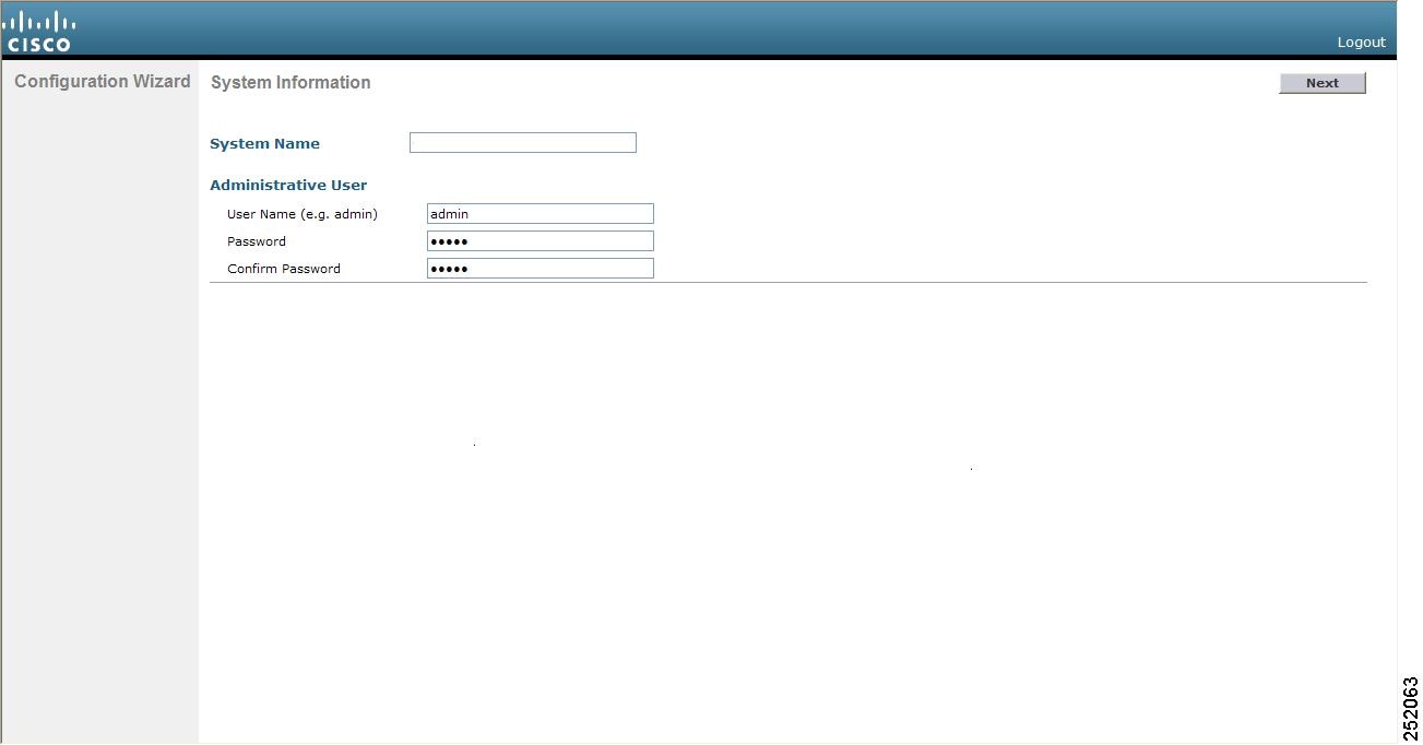
Step 3 In the System Name field, enter the name that you want to assign to this controller. You can enter up to 31 ASCII characters.
Step 4 In the User Name field, enter the administrative username to be assigned to this controller. You can enter up to 24 ASCII characters. The default username is admin .
Step 5 In the Password and Confirm Password fields, enter the administrative password to be assigned to this controller. You can enter up to 24 ASCII characters. The default password is admin .
Step 6 Click Next . The SNMP Summary page appears (see Figure 2).
Figure 2 Configuration Wizard — SNMP Summary Page
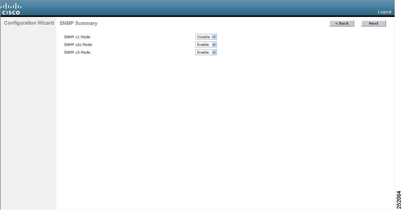
Step 7 If you want to enable Simple Network Management Protocol (SNMP) v1 mode for this controller, choose Enable from the SNMP v1 Mode drop-down box. Otherwise, leave this parameter set to Disable .
Note SNMP is a protocol that manages nodes (servers, workstations, routers, switches, and so on) on an IP network. Currently, there are three versions of SNMP: SNMPv1, SNMPv2c, and SNMPv3.
Step 8 If you want to enable SNMPv2c mode for this controller, leave this parameter set to Enable . Otherwise, choose Disable from the SNVP v2c Mode drop-down box.
Step 9 If you want to enable SNMPv3 mode for this controller, leave this parameter set to Enable . Otherwise, choose Disable from the SNVP v3 Mode drop-down box.
Step 11 When the following message appears, click OK :
Default values are present for v1/v2c community strings. Please make sure to create new v1/v2c community strings once the system comes up. Please make sure to create new v3 users once the system comes up.
Note Refer to the “Changing the Default Values of SNMP Community Strings” section and the “Changing the Default Values for SNMP v3 Users” section for instructions.
The Service Interface Configuration page appears (see Figure 3).
Figure 3 Configuration Wizard — Service Interface Configuration Page
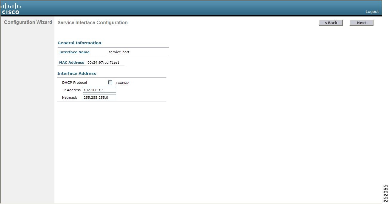
Step 12 If you want the controller’s service-port interface to obtain an IP address from a DHCP server, check the DHCP Protocol Enabled check box. If you do not want to use the service port or if you want to assign a static IP address to the service port, leave the check box unchecked.
Note The service-port interface controls communications through the service port. Its IP address must be on a different subnet from the management interface. This configuration enables you to manage the controller directly or through a dedicated management network to ensure service access during network downtime.
Step 13 Perform one of the following:
- If you enabled DHCP in If you want the controller’s service-port interface to obtain an IP address from a DHCP server, check the DHCP Protocol Enabled check box. If you do not want to use the service port or if you want to assign a static IP address to the service port, leave the check box unchecked., clear out any entries in the IP Address and Netmask fields, leaving them blank.
- If you disabled DHCP in If you want the controller’s service-port interface to obtain an IP address from a DHCP server, check the DHCP Protocol Enabled check box. If you do not want to use the service port or if you want to assign a static IP address to the service port, leave the check box unchecked., enter the static IP address and netmask for the service port in the IP Address and Netmask fields.
Step 14 Click Next . The LAG Configuration page appears (see Figure 4).
Figure 4 Configuration Wizard — LAG Configuration Page
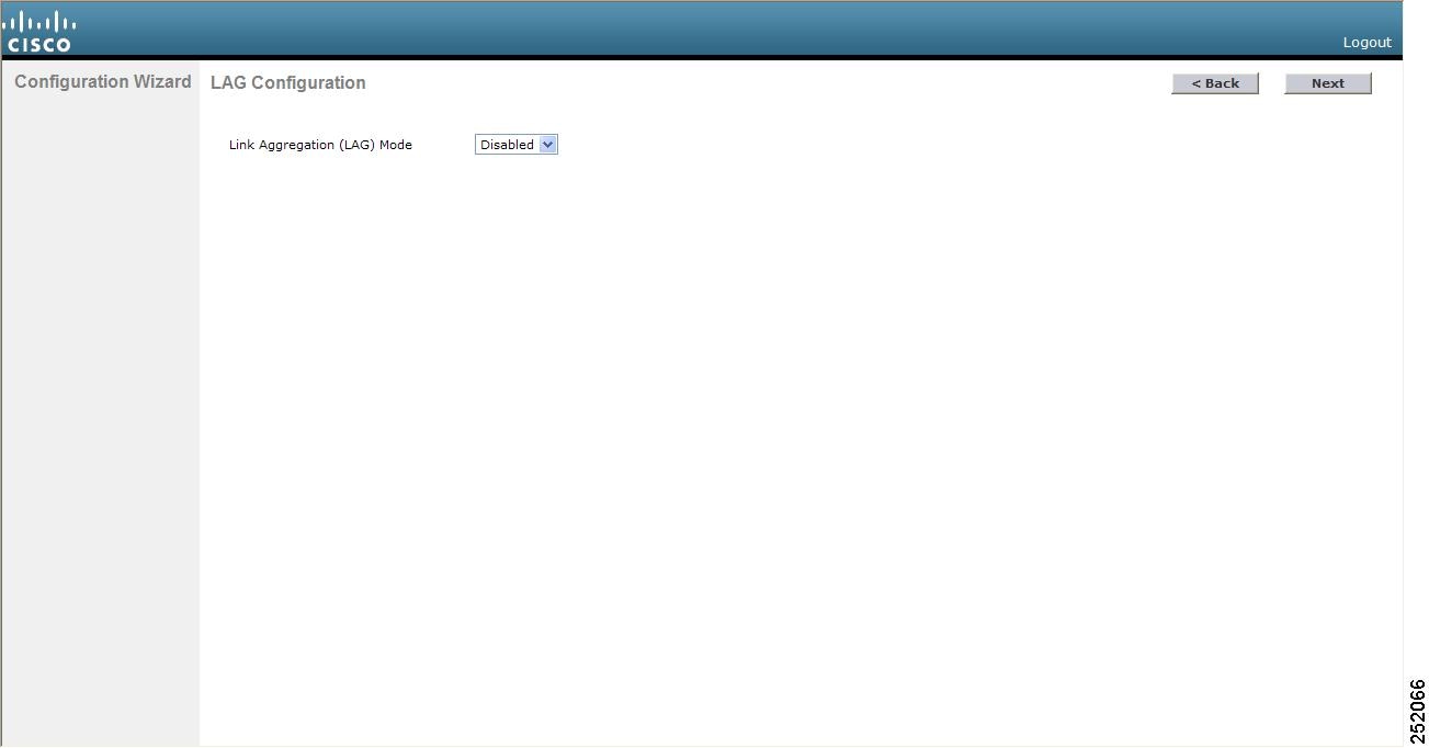
Step 15 To enable link aggregation (LAG), choose Enabled from the Link Aggregation (LAG) Mode drop-down box. To disable LAG, leave this field set to Disabled .
Step 16 Click Next . The Management Interface Configuration page appears (see Figure 5).
Figure 5 Configuration Wizard — Management Interface Configuration Page
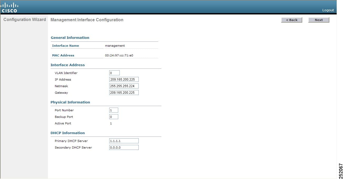
Note The management interface is the default interface for in-band management of the controller and connectivity to enterprise services such as AAA servers.
Step 17 In the VLAN Identifier field, enter VLAN identifier of the management interface (either a valid VLAN identifier or 0 for an untagged VLAN). The VLAN identifier should be set to match the switch interface configuration.
Step 18 In the IP Address field, enter the IP address of the management interface.
Step 19 In the Netmask field, enter the IP address of the management interface netmask.
Step 20 In the Gateway field, enter the IP address of the default gateway.
Step 21 In the Port Number field, enter the number of the port assigned to the management interface. Each interface is mapped to at least one primary port.
Step 22 In the Backup Port field, enter the number of the backup port assigned to the management interface. If the primary port for the management interface fails, the interface automatically moves to the backup port.
Step 23 In the Primary DHCP Server field, enter the IP address of the default DHCP server that will supply IP addresses to clients, the controller’s management interface, and optionally the service port interface.
Step 24 In the Secondary DHCP Server field, enter the IP address of an optional secondary DHCP server that will supply IP addresses to clients, the controller’s management interface, and optionally the service port interface.
Step 25 Click Next . The AP-Manager Interface Configuration page appears.
Note This page does not appear for 5500 series controllers because you are not required to configure an AP-manager interface. The management interface acts like an AP-manager interface by default.
Step 26 In the IP Address field, enter the IP address of the AP-manager interface.
Step 27 Click Next . The Miscellaneous Configuration page appears (see Figure 6).
Figure 6 Configuration Wizard — Miscellaneous Configuration Page
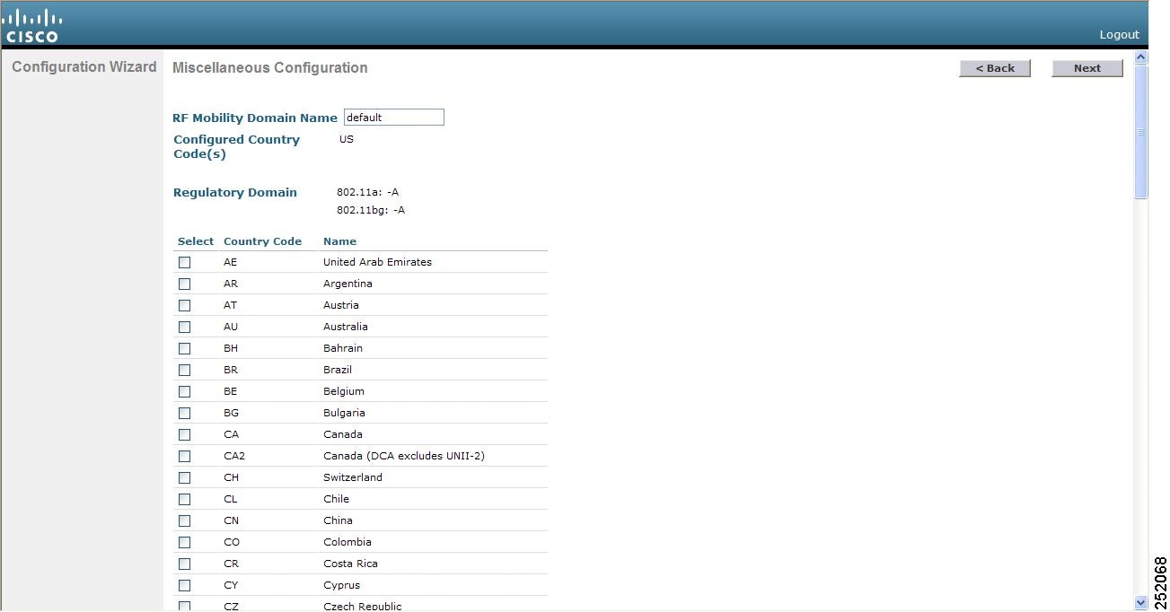
Step 28 In the RF Mobility Domain Name field, enter the name of the mobility group/RF group to which you want the controller to belong.
Note Although the name that you enter here is assigned to both the mobility group and the RF group, these groups are not identical. Both groups define clusters of controllers, but they have different purposes. All of the controllers in an RF group are usually also in the same mobility group and vice versa. However, a mobility group facilitates scalable, system-wide mobility and controller redundancy while an RF group facilitates scalable, system-wide dynamic RF management. See the Configuring Radio Resource Management and Configuring Mobility Groups chapters for more information.
Step 29 The Configured Country Code(s) field shows the code for the country in which the controller will be used. If you want to change the country of operation, check the check box for the desired country.
Note You can choose more than one country code if you want to manage access points in multiple countries from a single controller. After the configuration wizard runs, you need to assign each access point joined to the controller to a specific country. See the “Configuring Country Codes” section for instructions.
Step 31 When the following message appears, click OK :
Warning! To maintain regulatory compliance functionality, the country code setting may only be modified by a network administrator or qualified IT professional. Ensure that proper country codes are selected before proceeding.
The Virtual Interface Configuration page appears (see Figure 7).
Figure 7 Configuration Wizard — Virtual Interface Configuration Page
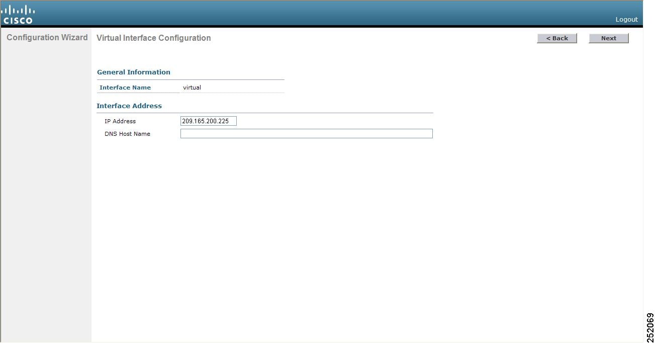
Step 32 In the IP Address field, enter the IP address of the controller’s virtual interface. You should enter a fictitious, unassigned IP address.
Note The virtual interface is used to support mobility management, DHCP relay, and embedded Layer 3 security such as guest web authentication and VPN termination. All controllers within a mobility group must be configured with the same virtual interface IP address.
Step 33 In the DNS Host Name field, enter the name of the Domain Name System (DNS) gateway used to verify the source of certificates when Layer 3 web authorization is enabled.
Note To ensure connectivity and web authentication, the DNS server should always point to the virtual interface. If a DNS host name is configured for the virtual interface, then the same DNS host name must be configured on the DNS servers used by the client.
Step 34 Click Next . The WLAN Configuration page appears (see Figure 8).
Figure 8 Configuration Wizard — WLAN Configuration Page
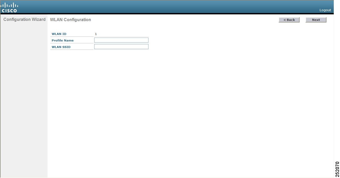
Step 35 In the Profile Name field, enter up to 32 alphanumeric characters for the profile name to be assigned to this WLAN.
Step 36 In the WLAN SSID field, enter up to 32 alphanumeric characters for the network name, or service set identifier (SSID). The SSID enables basic functionality of the controller and allows access points that have joined the controller to enable their radios.
Step 38 When the following message appears, click OK :
Default Security applied to WLAN is: [WPA2(AES)][Auth(802.1x)]. You can change this after the wizard is complete and the system is rebooted.
The RADIUS Server Configuration page appears (see Figure 9).
Figure 9 Configuration Wizard — RADIUS Server Configuration Page
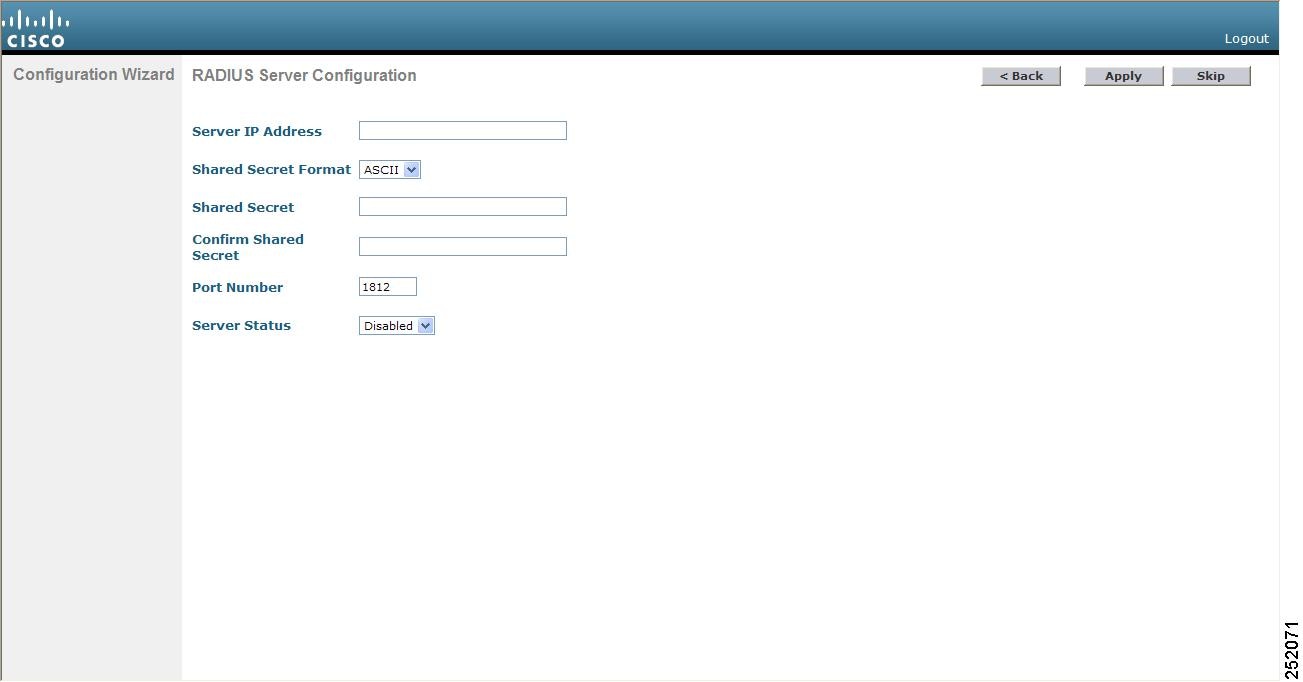
Step 39 In the Server IP Address field, enter the IP address of the RADIUS server.
Step 40 From the Shared Secret Format drop-down box, choose ASCII or Hex to specify the format of the shared secret.
Note Due to security reasons, the RADIUS shared secret key reverts to ASCII mode even if you have selected HEX as the shared secret format from the Shared Secret Format drop-down list.
Step 41 In the Shared Secret and Confirm Shared Secret fields, enter the secret key used by the RADIUS server.
Step 42 In the Port Number field, enter the communication port of the RADIUS server. The default value is 1812.
Step 43 To enable the RADIUS server, choose Enabled from the Server Status drop-down box. To disable the RADIUS server, leave this field set to Disabled .
Step 44 Click Apply . The 802.11 Configuration page appears (see Figure 10).
Figure 10 Configuration Wizard — 802.11 Configuration Page
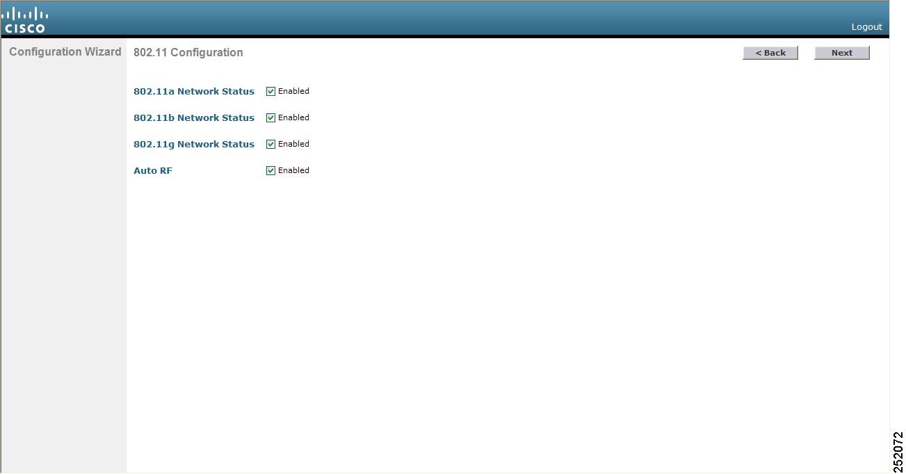
Step 45 To enable the 802.11a, 802.11b, and 802.11g lightweight access point networks, leave the 802.11a Network Status , 802.11b Network Status , and 802.11g Network Status check boxes checked. To disable support for any of these networks, uncheck the check boxes.
Step 46 To enable the controller’s radio resource management (RRM) auto-RF feature, leave the Auto RF check box checked. To disable support for the auto-RF feature, uncheck this check box. Refer to the Configuring Radio Resource Management chapter for more information on RRM.
Note The auto-RF feature enables the controller to automatically form an RF group with other controllers. The group dynamically elects a leader to optimize RRM parameter settings, such as channel and transmit power assignment, for the group.
Step 47 Click Next . The Set Time page appears (see Figure 11).
Figure 11 Configuration Wizard — Set Time Page
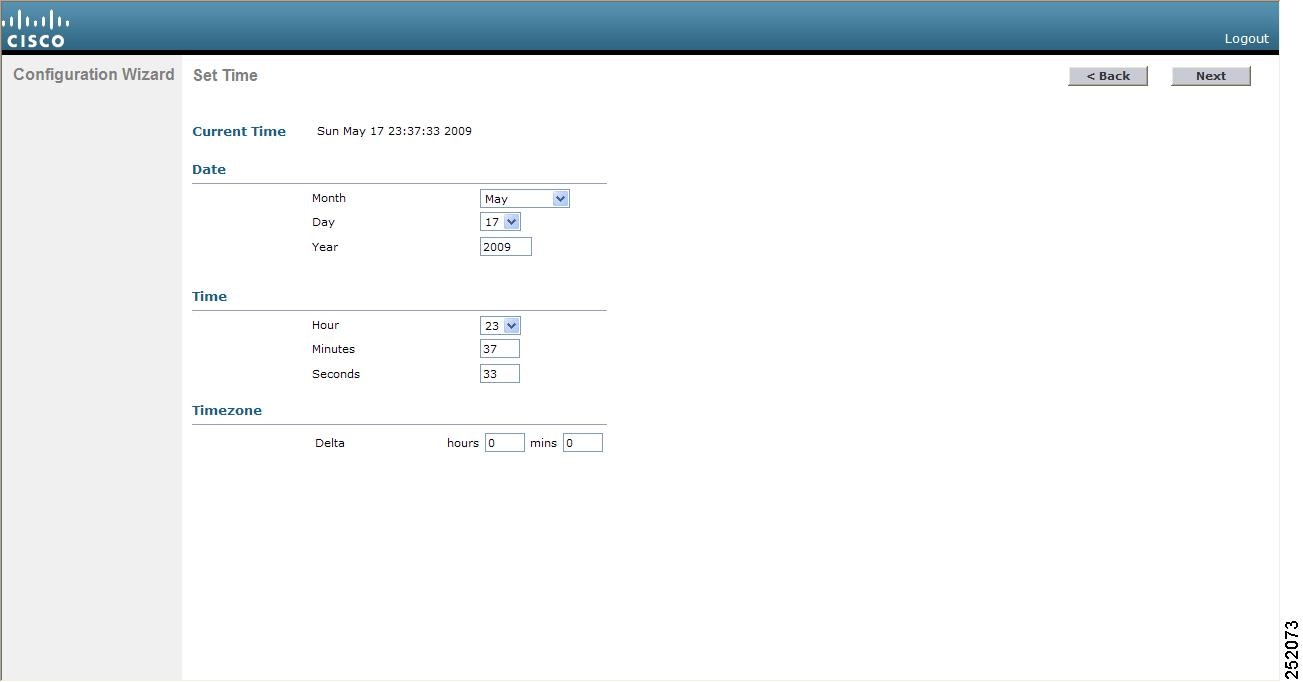
Step 48 To manually configure the system time on your controller, enter the current date in Month/DD/YYYY format and the current time in HH:MM:SS format.
Step 49 To manually set the time zone so that Daylight Saving Time (DST) is not set automatically, enter the local hour difference from Greenwich Mean Time (GMT) in the Delta Hours field and the local minute difference from GMT in the Delta Mins field.
Note When manually setting the time zone, enter the time difference of the local current time zone with respect to GMT (+/–). For example, Pacific time in the United States is 8 hours behind GMT. Therefore, it is entered as –8.
Step 50 Click Next . The Configuration Wizard Completed page appears (see Figure 12).
Figure 12 Configuration Wizard — Configuration Wizard Completed Page
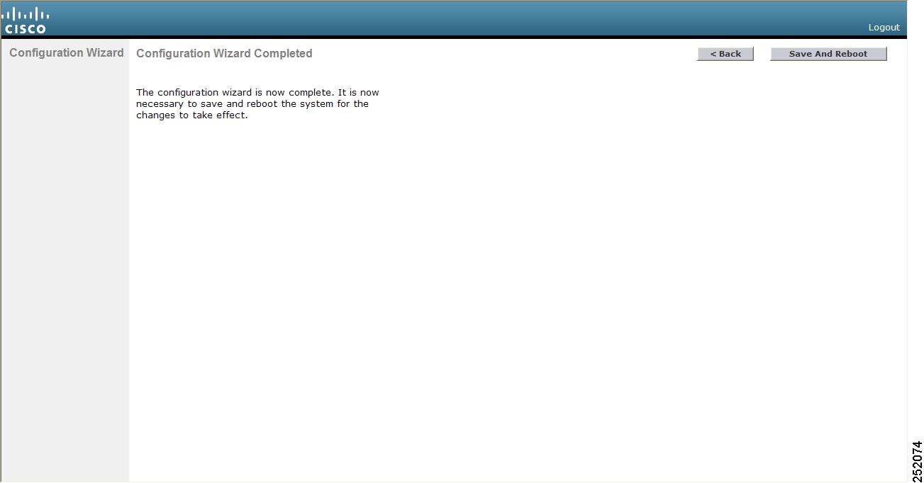
Step 51 Click Save and Reboot to save your configuration and reboot the controller.
Step 52 When the following message appears, click OK :
Step 53 The controller saves your configuration, reboots, and prompts you to log in. Follow the instructions in the “Using the GUI” section to log into the controller.
Using the CLI Configuration Wizard
Note The available options appear in brackets after each configuration parameter. The default value appears in all uppercase letters.
Note If you enter an incorrect response, the controller provides you with an appropriate error message, such as “Invalid Response,” and returns you to the wizard prompt.
Note Press the hyphen key if you ever need to return to the previous command line.
Follow these steps to configure the controller using the CLI configuration wizard.
Step 1 When prompted to terminate the AutoInstall process, enter yes . If you do not enter yes , the AutoInstall process begins after 30 seconds.
Note The AutoInstall feature downloads a configuration file from a TFTP server and then loads the configuration onto the controller automatically. Refer to the “Using the AutoInstall Feature for Controllers Without a Configuration” section for more information.
Note The Cisco WiSM controllers do not support the AutoInstall feature.
Step 2 Enter the system name, which is the name you want to assign to the controller. You can enter up to 31 ASCII characters.
Step 3 Enter the administrative username and password to be assigned to this controller. You can enter up to 24 ASCII characters for each. The default administrative username and password are admin and admin, respectively.
Step 4 If you want the controller’s service-port interface to obtain an IP address from a DHCP server, enter DHCP . If you do not want to use the service port or if you want to assign a static IP address to the service port, enter none.
Note The service-port interface controls communications through the service port. Its IP address must be on a different subnet from the management interface. This configuration enables you to manage the controller directly or through a dedicated management network to ensure service access during network downtime.
Step 5 If you entered none in If you want the controller’s service-port interface to obtain an IP address from a DHCP server, enter DHCP. If you do not want to use the service port or if you want to assign a static IP address to the service port, enter none., enter the IP address and netmask for the service-port interface on the next two lines.
Step 6 Enable or disable link aggregation (LAG) by choosing yes or NO. Refer to the Configuring Ports and Interfaces chapter for more information on LAG.
Step 7 Enter the IP address of the management interface.
Note The management interface is the default interface for in-band management of the controller and connectivity to enterprise services such as AAA servers.
Step 8 Enter the IP address of the management interface netmask.
Step 9 Enter the IP address of the default router.
Step 10 Enter the VLAN identifier of the management interface (either a valid VLAN identifier or 0 for an untagged VLAN). The VLAN identifier should be set to match the switch interface configuration.
Step 11 Enter the IP address of the default DHCP server that will supply IP addresses to clients, the controller’s management interface, and optionally the service port interface.
Step 12 Enter the IP address of the AP-manager interface.
Note This prompt does not appear for 5500 series controllers because you are not required to configure an AP-manager interface. The management interface acts like an AP-manager interface by default.
Step 13 Enter the IP address of the controller’s virtual interface. You should enter a fictitious, unassigned IP address.
Note The virtual interface is used to support mobility management, DHCP relay, and embedded Layer 3 security such as guest web authentication and VPN termination. All controllers within a mobility group must be configured with the same virtual interface IP address.
Step 14 If desired, enter the name of the mobility group/RF group to which you want the controller to belong.
Note Although the name that you enter here is assigned to both the mobility group and the RF group, these groups are not identical. Both groups define clusters of controllers, but they have different purposes. All of the controllers in an RF group are usually also in the same mobility group and vice versa. However, a mobility group facilitates scalable, system-wide mobility and controller redundancy while an RF group facilitates scalable, system-wide dynamic RF management. See the Configuring Radio Resource Management and Configuring Mobility Groups chapters for more information.
Step 15 Enter the network name, or service set identifier (SSID). The SSID enables basic functionality of the controller and allows access points that have joined the controller to enable their radios.
Step 16 Enter YES to allow clients to assign their own IP address or no to require clients to request an IP address from a DHCP server.
Step 17 To configure a RADIUS server now, enter YES and then enter the IP address, communication port, and secret key of the RADIUS server. Otherwise, enter no. If you enter no, the following message appears: “Warning! The default WLAN security policy requires a RADIUS server. Please see documentation for more details.”
Step 18 Enter the code for the country in which the controller will be used.
Note Enter help to view the list of available country codes.
Note You can enter more than one country code if you want to manage access points in multiple countries from a single controller. To do so, separate the country codes with a comma (for example, US,CA,MX). After the configuration wizard runs, you need to assign each access point joined to the controller to a specific country. See the “Configuring Country Codes” section for instructions.
Step 19 Enable or disable the 802.11b, 802.11a, and 802.11g lightweight access point networks by entering YES or no.
Step 20 Enable or disable the controller’s radio resource management (RRM) auto-RF feature by entering YES or no. Refer to the Configuring Radio Resource Management chapter for more information on RRM.
Note The auto-RF feature enables the controller to automatically form an RF group with other controllers. The group dynamically elects a leader to optimize RRM parameter settings, such as channel and transmit power assignment, for the group.
Step 21 If you want the controller to receive its time setting from an external Network Time Protocol (NTP) server when it powers up, enter YES to configure an NTP server. Otherwise, enter no .
Note The controller network module installed in a Cisco Integrated Services Router does not have a battery and cannot save a time setting. Therefore, it must receive a time setting from an external NTP server when it powers up.
Step 22 If you entered no in If you want the controller to receive its time setting from an external Network Time Protocol (NTP) server when it powers up, enter YES to configure an NTP server. Otherwise, enter no. and want to manually configure the system time on your controller now, enter YES . If you do not want to configure the system time now, enter no .
Step 23 If you entered YES in If you entered no in Step 21 and want to manually configure the system time on your controller now, enter YES. If you do not want to configure the system time now, enter no., enter the current date in MM/DD/YY format and the current time in HH:MM:SS format.
Step 24 When prompted to verify that the configuration is correct, enter yes or NO .
The controller saves your configuration, reboots, and prompts you to log in. Follow the instructions in the “Using the CLI” section to log into the controller.
Using the GUI
A web-browser, or graphical user interface (GUI), is built into each controller. It allows up to five users to simultaneously browse into the controller HTTP or HTTPS (HTTP + SSL) management pages to configure parameters and monitor operational status for the controller and its associated access points.
Note Cisco recommends that you enable the HTTPS interface and disable the HTTP interface to ensure more robust security for your Cisco UWN Solution.
Guidelines for Using the GUI
Keep these guidelines in mind when using the GUI:
- The GUI must be used on a PC running Windows XP SP1 (or later) or Windows 2000 SP4 (or later).
- The GUI is fully compatible with Microsoft Internet Explorer version 6.0 SP1 (or later) or Mozilla Firefox 2.0.0.11 (or later).
Note Opera and Netscape are not supported.
Note Internet Explorer 6.0 SP1 (or later) and Mozilla Firefox 2.0.0.11 (or later) are the only browsers supported for accessing the controller GUI and for using web authentication.
- You can use either the service port interface or the management interface to access the GUI. Cisco recommends that you use the service-port interface. Refer to the Configuring Ports and Interfaces chapter for instructions on configuring the service port interface.
- Click Help at the top of any page in the GUI to display online help. You might need to disable your browser’s pop-up blocker to view the online help.
Logging into the GUI
Follow these steps to log into the controller GUI.
Step 1 Enter the controller IP address in your browser’s address line. For a secure connection, enter https: //ip-address . For a less secure connection, enter http: //ip-address .
Note See the “Using the GUI to Enable Web and Secure Web Modes” section for instructions on setting up HTTPS.
Step 2 When prompted, enter a valid username and password and click OK . The controller Summary page appears.
Note The administrative username and password that you created in the configuration wizard are case sensitive. The default username is admin, and the default password is admin.
Logging Out of the GUI
To logout out of the controller GUI, follow these steps:
Step 1 Click Logout in the top right corner of the screen.
Step 2 Click Close to complete the logoff process and prevent unauthorized users from accessing the controller GUI.
Step 3 When prompted to confirm your decision, click Yes .
Enabling Web and Secure Web Modes
This section provides instructions for enabling the distribution system port as a web port (using HTTP) or as a secure web port (using HTTPS). You can protect communication with the GUI by enabling HTTPS. HTTPS protects HTTP browser sessions by using the Secure Socket Layer (SSL) protocol. When you enable HTTPS, the controller generates its own local web administration SSL certificate and automatically applies it to the GUI. You also have the option of downloading an externally generated certificate.
You can configure web and secure web mode using the controller GUI or CLI.
Using the GUI to Enable Web and Secure Web Modes
Follow these steps to enable web mode, secure web mode, or both using the controller GUI.
Step 1 Choose Management > HTTP to open the HTTP Configuration page (see Figure 13).
Figure 13 HTTP Configuration Page

Step 2 To enable web mode, which allows users to access the controller GUI using “http:// ip-address ,” choose Enabled from the HTTP Access drop-down box. Otherwise, choose Disabled . The default value is Disabled. Web mode is not a secure connection.
Step 3 To enable secure web mode, which allows users to access the controller GUI using “https:// ip-address ,” choose Enabled from the HTTPS Access drop-down box. Otherwise, choose Disabled . The default value is Enabled. Secure web mode is a secure connection.
Step 4 In the Web Session Timeout field, enter the amount of time (in minutes) before the web session times out due to inactivity. You can enter a value between 30 and 160 minutes (inclusive), and the default value is 30 minutes.
Step 5 Click Apply to commit your changes.
Step 6 If you enabled secure web mode in Step 3, the controller generates a local web administration SSL certificate and automatically applies it to the GUI. The details of the current certificate appear in the middle of the HTTP Configuration page (see Figure 13).
Note If you want to download your own SSL certificate to the controller, follow the instructions in the “Loading an Externally Generated SSL Certificate” section.
Note If desired, you can delete the current certificate by clicking Delete Certificate and have the controller generate a new certificate by clicking Regenerate Certificate.
Step 7 Click Save Configuration to save your changes.
Using the CLI to Enable Web and Secure Web Modes
Follow these steps to enable web mode, secure web mode, or both using the controller CLI.
Step 1 To enable or disable web mode, enter this command:
config network webmode {enable | disable}
This command allows users to access the controller GUI using “http:// ip-address.” The default value is disabled. Web mode is not a secure connection.
Step 2 To enable or disable secure web mode, enter this command:
config network secureweb {enable | disable}
This command allows users to access the controller GUI using “https:// ip-address .” The default value is enabled. Secure web mode is a secure connection.
Step 3 To enable or disable secure web mode with increased security, enter this command:
config network secureweb cipher-option high { enable | disable }
This command allows users to access the controller GUI using “https:// ip-address ” but only from browsers that support 128-bit (or larger) ciphers. The default value is disabled.
Step 4 To enable or disable SSLv2 for web administration, enter this command:
config network secureweb cipher-option sslv2 { enable | disable }
If you disable SSLv2, users cannot connect using a browser configured with SSLv2 only. They must use a browser that is configured to use a more secure protocol such as SSLv3 or later. The default value is enabled.
Step 5 To verify that the controller has generated a certificate, enter this command:
Information similar to the following appears:
Note If you want to download your own SSL certificate to the controller, follow the instructions in the “Loading an Externally Generated SSL Certificate” section.
Step 6 (Optional) If you need to generate a new certificate, enter this command:
config certificate generate webadmin
After a few seconds, the controller verifies that the certificate has been generated.
Step 7 To save the SSL certificate, key, and secure web password to non-volatile RAM (NVRAM) so that your changes are retained across reboots, enter this command:
Step 8 To reboot the controller, enter this command:
Loading an Externally Generated SSL Certificate
You can use a TFTP server to download an externally generated SSL certificate to the controller. Follow these guidelines for using TFTP:
- If you load the certificate through the service port, the TFTP server must be on the same subnet as the controller because the service port is not routable, or you must create static routes on the controller. Also, if you load the certificate through the distribution system network port, the TFTP server can be on any subnet.
- A third-party TFTP server cannot run on the same PC as the Cisco WCS because the WCS built-in TFTP server and the third-party TFTP server require the same communication port.
Note Chained certificates are supported for web authentication only and not for the management certificate.
Note Every HTTPS certificate contains an embedded RSA key. The length of the key can vary from 512 bits, which is relatively insecure, to thousands of bits, which is very secure. When you obtain a new certificate from a Certificate Authority, make sure that the RSA key embedded in the certificate is at least 768 bits long.
Using the GUI to Load an SSL Certificate
Follow these steps to load an externally generated SSL certificate using the controller GUI.
Step 1 On the HTTP Configuration page, check the Download SSL Certificate check box (see Figure 14).
Figure 14 HTTP Configuration Page
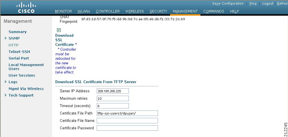
Step 2 In the Server IP Address field, enter the IP address of the TFTP server.
Step 3 In the Maximum Retries field, enter the maximum number of times that the TFTP server attempts to download the certificate.
Step 4 In the Timeout field, enter the amount of time (in seconds) that the TFTP server attempts to download the certificate.
Step 5 In the Certificate File Path field, enter the directory path of the certificate.
Step 6 In the Certificate File Name field, enter the name of the certificate (webadmincert_name.pem).
Step 7 (Optional) In the Certificate Password field, enter a password to encrypt the certificate.
Step 8 Click Apply to commit your changes.
Step 9 Click Save Configuration to save your changes.
Step 10 To reboot the controller for your changes to take effect, choose Commands > Reboot > Reboot > Save and Reboot .
Using the CLI to Load an SSL Certificate
Follow these steps to load an externally generated SSL certificate using the controller CLI.
Step 1 Use a password to encrypt the HTTPS certificate in a .PEM-encoded file. The PEM-encoded file is called a web administration certificate file (webadmincert_name.pem).
Step 2 Move the webadmincert_name.pem file to the default directory on your TFTP server.
Step 3 To view the current download settings, enter this command and answer n to the prompt:
Information similar to the following appears:
Step 4 Use these commands to change the download settings:
transfer download datatype webauthcert
transfer download serverip TFTP_server IP_address
transfer download path absolute_TFTP_server_path_to_the_update_file
transfer download filename webadmincert_name.pem
Step 5 To set the password for the .PEM file so that the operating system can decrypt the web administration SSL key and certificate, enter this command:
transfer download certpassword private_key_password
Step 6 To confirm the current download settings and start the certificate and key download, enter this command and answer y to the prompt:
Information similar to the following appears:
Step 7 To save the SSL certificate, key, and secure web password to NVRAM so that your changes are retained across reboots, enter this command:
Step 8 To reboot the controller, enter this command:
Using the CLI
A Cisco UWN Solution command line interface (CLI) is built into each controller. The CLI allows you to use a VT-100 terminal emulation program to locally or remotely configure, monitor, and control individual controllers and its associated lightweight access points. The CLI is a simple text-based, tree-structured interface that allows up to five users with Telnet-capable terminal emulation programs to access the controller.
Note Refer to the Cisco Wireless LAN Controller Command Reference for information on specific commands.
Note If you want to input any strings from the XML configuration into CLI commands, you must enclose the strings in quotation marks.
Logging into the CLI
You access the controller CLI using one of two methods:
- A direct serial connection to the controller console port
- A remote console session over Ethernet through the pre-configured service port or the distribution system ports
Before you log into the CLI, configure your connectivity and environment variables based on the type of connection you use.
Using a Local Serial Connection
You need these items to connect to the serial port:
- A PC that is running a VT-100 terminal emulation program (such as HyperTerminal, ProComm, Minicom, or Tip)
- A null-modem serial cable
Follow these steps to log into the controller CLI through the serial port.
Step 1 Connect one end of a null-modem serial cable to the controller’s console port and the other end to your PC’s serial port.
Note On 5500 series controllers, you can use either the RJ-45 console port or the USB console port. If you use the USB console port, plug the 5-pin mini Type B connector into the controller’s USB console port and the other end of the cable into the PC’s USB Type A port. The first time that you connect a Windows PC to the USB console port, you are prompted to install the USB console driver. Follow the installation prompts to install the driver. The USB console driver maps to a COM port on your PC; you then need to map the terminal emulator application to the COM port.
Step 2 Start the PC’s VT-100 terminal emulation program.
Step 3 Configure the terminal emulation program for these parameters:
Note The controller serial port is set for a 9600 baud rate and a short timeout. If you would like to change either of these values, enter config serial baudrate baudrate and config serial timeout timeout to make your changes. If you enter config serial timeout 0, serial sessions never time out.
Step 4 When prompted, enter a valid username and password to log into the controller. The administrative username and password that you created in the configuration wizard are case sensitive.
Note The default username is admin, and the default password is admin.
The CLI displays the root level system prompt:
Note The system prompt can be any alphanumeric string up to 31 characters. You can change it by entering the config prompt command.
Using a Remote Ethernet Connection
You need these items to connect to a controller remotely:
- A PC with access to the controller over the Ethernet network
- The IP address of the controller
- A VT-100 terminal emulation program or a DOS shell for the Telnet session
Note By default, controllers block Telnet sessions. You must use a local connection to the serial port to enable Telnet sessions. See the “Configuring Telnet and SSH Sessions” section for information on enabling Telnet sessions.
Follow these steps to log into the controller CLI through a remote Ethernet connection.
Step 1 Verify that your VT-100 terminal emulation program or DOS shell interface is configured with these parameters:
Step 2 Use the controller IP address to Telnet to the CLI.
Step 3 When prompted, enter a valid username and password to log into the controller. The administrative username and password that you created in the configuration wizard are case sensitive.
Note The default username is admin, and the default password is admin.
The CLI displays the root level system prompt:
Note The system prompt can be any alphanumeric string up to 31 characters. You can change it by entering the config prompt command.
Logging Out of the CLI
When you finish using the CLI, navigate to the root level and enter logout. The system prompts you to save any changes you made to the volatile RAM.
Note The CLI automatically logs you out without saving any changes after 5 minutes of inactivity. You can set the automatic logout from 0 (never log out) to 160 minutes using the config serial timeout command.
Navigating the CLI
The CLI is organized around five levels:
When you log into the CLI, you are at the root level. From the root level, you can enter any full command without first navigating to the correct command level. Table 1 lists commands you use to navigate the CLI and to perform common tasks.
Using the AutoInstall Feature for Controllers Without a Configuration
When you boot up a controller that does not have a configuration, the AutoInstall feature can download a configuration file from a TFTP server and then load the configuration onto the controller automatically.
Note The Cisco WiSM controllers do not support the AutoInstall feature.
Overview of AutoInstall
If you create a configuration file on a controller that is already on the network (or through a WCS filter), place that configuration file on a TFTP server, and configure a DHCP server so that a new controller can get an IP address and TFTP server information, the AutoInstall feature can obtain the configuration file for the new controller automatically.
When the controller boots, the AutoInstall process starts. The controller does not take any action until AutoInstall is notified that the configuration wizard has started. If the wizard has not started, the controller has a valid configuration.
If AutoInstall is notified that the configuration wizard has started (which means that the controller does not have a configuration), AutoInstall waits for an additional 30 seconds. This time period gives you an opportunity to respond to the first prompt from the configuration wizard:
When the 30-second abort timeout expires, AutoInstall starts the DHCP client. You can abort the AutoInstall task even after this 30-second timeout if you enter Yes at the prompt. However, AutoInstall cannot be aborted if the TFTP task has locked the flash and is in the process of downloading and installing a valid configuration file.
Obtaining an IP Address Through DHCP and Downloading a Configuration File from a TFTP Server
AutoInstall uses the following interfaces:
– eth0—Service port (untagged)
– dtl0—Gigabit port 1 through the NPU (untagged)
– dtl0—FastEthernet port 1 (untagged)
AutoInstall attempts to obtain an IP address from the DHCP server until the DHCP process is successful or until you abort the AutoInstall process. The first interface to successfully obtain an IP address from the DHCP server registers with the AutoInstall task. The registration of this interface causes AutoInstall to begin the process of obtaining TFTP server information and downloading the configuration file.
Following the acquisition of the DHCP IP address for an interface, AutoInstall begins a short sequence of events to determine the host name of the controller and the IP address of the TFTP server. Each phase of this sequence gives preference to explicitly configured information over default or implied information and to explicit host names over explicit IP addresses.
- If at least one Domain Name System (DNS) server IP address is learned through DHCP, AutoInstall creates a /etc/resolv.conf file. This file includes the domain name and the list of DNS servers that have been received. The Domain Name Server option provides the list of DNS servers, and the Domain Name option provides the domain name.
- If the domain servers are not on the same subnet as the controller, static route entries are installed for each domain server. These static routes point to the gateway that is learned through the DHCP Router option.
- The host name of the controller is determined in this order by one of the following:
– If the DHCP Host Name option was received, this information (truncated at the first period [.]) is used as the host name for the controller.
– A reverse DNS lookup is performed on the controller IP address. If DNS returns a host name, this name (truncated at the first period [.]) is used as the host name for the controller.
– If AutoInstall received the DHCP TFTP Server Name option, AutoInstall performs a DNS lookup on this server name. If the DNS lookup is successful, the returned IP address is used as the IP address of the TFTP server.
– If the DHCP Server Host Name (sname) field is valid, AutoInstall performs a DNS lookup on this name. If the DNS lookup is successful, the IP address that is returned is used as the IP address of the TFTP server.
– If AutoInstall received the DHCP TFTP Server Address option, this address is used as the IP address of the TFTP server.
– AutoInstall performs a DNS lookup on the default TFTP server name (cisco-wlc-tftp). If the DNS lookup is successful, the IP address that is received is used as the IP address of the TFTP server.
– If the DHCP server IP address (siaddr) field is non-zero, this address is used as the IP address of the TFTP server.
– The limited broadcast address (255.255.255.255) is used as the IP address of the TFTP server.
- If the TFTP server is not on the same subnet as the controller, a static route (/32) is installed for the IP address of the TFTP server. This static route points to the gateway that is learned through the DHCP Router option.
Note For more information on configuring DHCP on a controller, see the “Configuring DHCP” section.
Note For more information on configuring a TFTP server on a controller, see the Managing Controller Software and Configurations chapter.
Note For more information on configuring DHCP and TFTP servers through WCS, see Chapter 10 of the Cisco Wireless Control System Configuration Guide, Release 6.0.
Selecting a Configuration File
After the host name and TFTP server have been determined, AutoInstall attempts to download a configuration file. AutoInstall performs three full download iterations on each interface that obtains a DHCP IP address. For example, if a 4400 series controller obtains DHCP IP addresses on both eth0 and dtl0, each interface tries to download a configuration. If the interface cannot download a configuration file successfully after three attempts, the interface does not attempt further.
The first configuration file that is downloaded and installed successfully triggers a reboot of the controller. After the reboot, the controller runs the newly downloaded configuration.
AutoInstall searches for configuration files in the order in which the names are listed:
- The filename that is provided by the DHCP Boot File Name option
- The filename that is provided by the DHCP File field
- host name -confg
- host name .cfg
- base MAC addres s-confg (for example, 0011.2233.4455-confg)
- serial number -confg
- ciscowlc-confg
- ciscowlc.cfg
AutoInstall runs through this list until it finds a configuration file. It stops running if it does not find a configuration file after it cycles through this list three times on each registered interface.
Note The downloaded configuration file can be a complete configuration, or it can be a minimal configuration that provides enough information for the controller to be managed by WCS. Full configuration can then be deployed directly from WCS.
Note For information about creating and uploading a configuration file that AutoInstall can obtain from a TFTP server, see the Managing Controller Software and Configurations chapter.
Note WCS release 5.0 or later provides AutoInstall capabilities for controllers. A WCS administrator can create a filter that includes the host name, the MAC address, or the serial number of the controller and associate a group of templates (a configuration group) to this filter rule. WCS pushes the initial configuration to the controller when the controller boots up initially. After the controller is discovered, WCS pushes the templates that are defined in the configuration group. For more information about the AutoInstall feature and WCS, see Chapter 15 of the Cisco Wireless Control System Configuration Guide, Release 6.0.
Managing the System Date and Time
If you did not configure the system date and time through the configuration wizard or if you want to change your configuration, you can follow the instructions in this section to configure the controller to obtain the date and time from a Network Time Protocol (NTP) server or to configure the date and time manually. Greenwich Mean Time (GMT) is used as the standard for setting the time zone on the controller.
Note Cisco Aironet lightweight access points might not connect to the controller if the date and time are not set properly. Set the current date and time on the controller before allowing the access points to connect to it.
Configuring an NTP Server to Obtain the Date and Time
Each NTP server IP address is added to the controller database. Each controller searches for an NTP server and obtains the current time upon reboot and at each user-defined polling interval (daily to weekly).
Use these commands to configure an NTP server to obtain the date and time:
1. To specify the NTP server for the controller, enter this command:
config time ntp server index ip_address
2. To specify the polling interval (in seconds), enter this command:
Configuring the Date and Time Manually
Follow the instructions in this section to configure the date and time manually using the controller GUI or CLI.
Using the GUI to Configure the Date and Time
Using the controller GUI, follow these steps to configure the local date and time.
Step 1 Choose Commands > Set Time to open the Set Time page (see Figure 15).
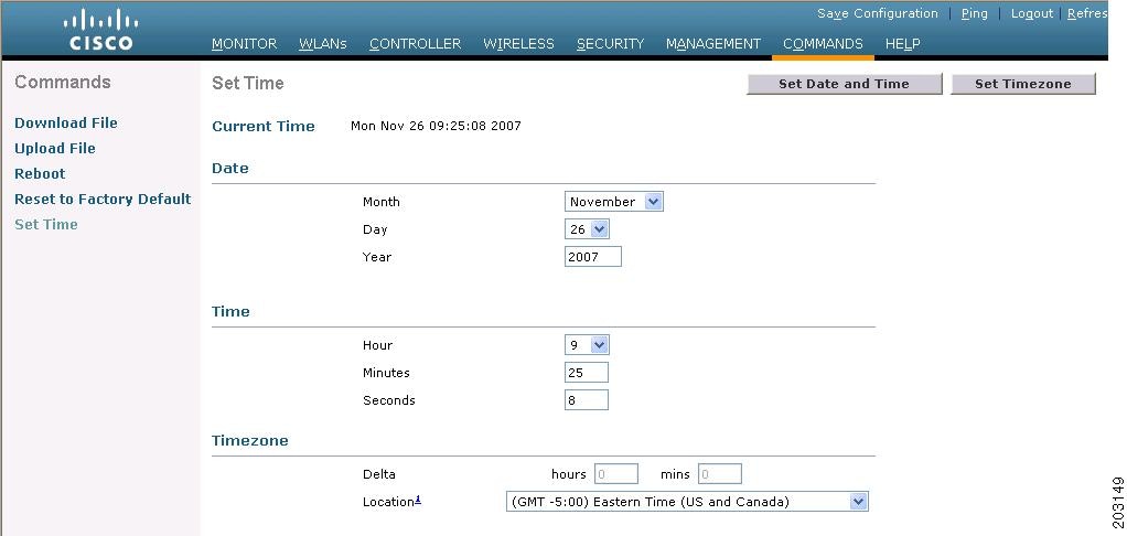
The current date and time appear at the top of the page.
Step 2 In the Timezone section, choose your local time zone from the Location drop-down box.
Note When you choose a time zone that uses Daylight Saving Time (DST), the controller automatically sets its system clock to reflect the time change when DST occurs. In the United States, DST starts on the second Sunday in March and ends on the first Sunday in November.
Note You cannot set the time zone delta on the controller GUI. However, if you do so on the controller CLI, the change is reflected in the Delta Hours and Mins fields on the controller GUI.
Step 3 Click Set Timezone to apply your changes.
Step 4 In the Date section, choose the current local month and day from the Month and Day drop-down boxes, and enter the year in the Year field.
Step 5 In the Time section, choose the current local hour from the Hour drop-down box, and enter the minutes and seconds in the Minutes and Seconds fields.
Note If you change the time zone location after setting the date and time, the values in the Time section are updated to reflect the time in the new time zone location. For example, if the controller is currently configured for noon Eastern time and you change the time zone to Pacific time, the time automatically changes to 9:00 a.m.
Step 6 Click Set Date and Time to apply your changes.
Step 7 Click Save Configuration to save your changes.
Using the CLI to Configure the Date and Time
Using the controller CLI, follow these steps to configure the local date and time.
Step 1 To configure the current local date and time in GMT on the controller, enter this command:
config time manual mm/dd/yy hh:mm:ss
Note When setting the time, the current local time is entered in terms of GMT and as a value between 00:00 and 24:00. For example, if it is 8:00 a.m. Pacific time in the United States, you would enter 16:00 because the Pacific time zone is 8 hours behind GMT.
Step 2 Perform one of the following to set the time zone for the controller:
- To set the time zone location in order to have Daylight Saving Time (DST) set automatically when it occurs, enter this command:
config time timezone location location_index
where location_index is a number representing one of the following time zone locations:
– 1. (GMT-12:00) International Date Line West
– 5. (GMT-8:00) Pacific Time (US and Canada)
– 6. (GMT-7:00) Mountain Time (US and Canada)
– 7. (GMT-6:00) Central Time (US and Canada)
– 8. (GMT-5:00) Eastern Time (US and Canada)
– 9. (GMT-4:00) Atlantic Time (Canada)
– 10. (GMT-3:00) Buenos Aires (Argentina)
– 13. (GMT) London, Lisbon, Dublin, Edinburgh (default value)
– 14. (GMT +1:00) Amsterdam, Berlin, Rome, Vienna
– 17. (GMT +4:00) Muscat, Abu Dhabi
– 19. (GMT +5:00) Karachi, Islamabad, Tashkent
– 20. (GMT +5:30) Colombo, Kolkata, Mumbai, New Delhi
– 22. (GMT +6:00) Almaty, Novosibirsk
– 24. (GMT +7:00) Saigon, Hanoi, Bangkok, Jakatar
– 25. (GMT +8:00) Hong Kong, Bejing, Chongquing
– 26. (GMT +9:00) Tokyo, Osaka, Sapporo
– 28. (GMT+10:00) Sydney, Melbourne, Canberra
– 29. (GMT+11:00) Magadan, Solomon Is., New Caledonia
– 30. (GMT+12:00) Kamchatka, Marshall Is., Fiji
Note If you enter this command, the controller automatically sets its system clock to reflect DST when it occurs. In the United States, DST starts on the second Sunday in March and ends on the first Sunday in November.
config time timezone delta_hours delta_mins
where delta_hours is the local hour difference from GMT, and delta_mins is the local minute difference from GMT.
When manually setting the time zone, enter the time difference of the local current time zone with respect to GMT (+/–). For example, Pacific time in the United States is 8 hours behind GMT. Therefore, it is entered as –8.
Note You can manually set the time zone and prevent DST from being set only on the controller CLI.
Step 3 To save your changes, enter this command:
Step 4 To verify that the controller shows the current local time with respect to the local time zone, enter this command:
Information similar to the following appears:
Note If you configured the time zone location, the Timezone Delta value is set to “0:0.” If you manually configured the time zone using the time zone delta, the Timezone Location is blank.
Configuring Telnet and SSH Sessions
Telnet is a network protocol used to provide access to the controller’s CLI. Secure Shell (SSH) is a more secure version of Telnet that uses data encryption and a secure channel for data transfer. You can use the controller GUI or CLI to configure Telnet and SSH sessions.
Note Refer to the “Troubleshooting Access Points Using Telnet or SSH” section for instructions on using Telnet or SSH to troubleshoot lightweight access points.
Using the GUI to Configure Telnet and SSH Sessions
Using the controller GUI, follow these steps to configure Telnet and SSH sessions.
Step 1 Choose Management > Telnet-SSH to open the Telnet-SSH Configuration page (see Figure 16).
Figure 16 Telnet-SSH Configuration Page
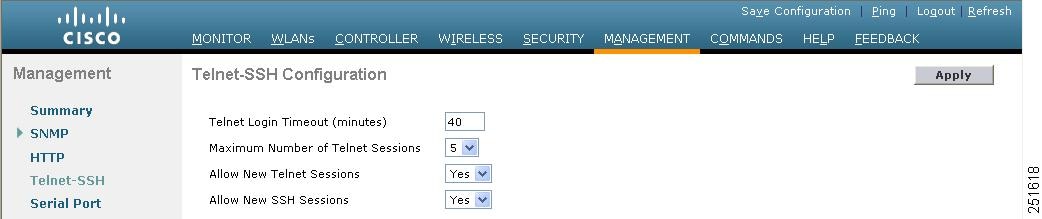
Step 2 In the Telnet Login Timeout field, enter the number of minutes that a Telnet session is allowed to remain inactive before being terminated. The valid range is 0 to 160 minutes (inclusive), and the default value is 5 minutes. A value of 0 indicates no timeout.
Step 3 From the Maximum Number of Telnet Sessions drop-down box, choose the number of simultaneous Telnet sessions allowed. The valid range is 0 to 5 sessions (inclusive), and the default value is 5 sessions.
Step 4 From the Allow New Telnet Sessions drop-down box, choose Yes or No to allow or disallow new Telnet sessions on the controller. The default value is No.
Step 5 From the Allow New SSH Sessions drop-down box, choose Yes or No to allow or disallow new SSH sessions on the controller. The default value is Yes.
Step 6 Click Apply to commit your changes.
Step 7 Click Save Configuration to save your changes.
Step 8 To see a summary of the Telnet configuration settings, choose Management > Summary . The Summary page appears (see Figure 17).
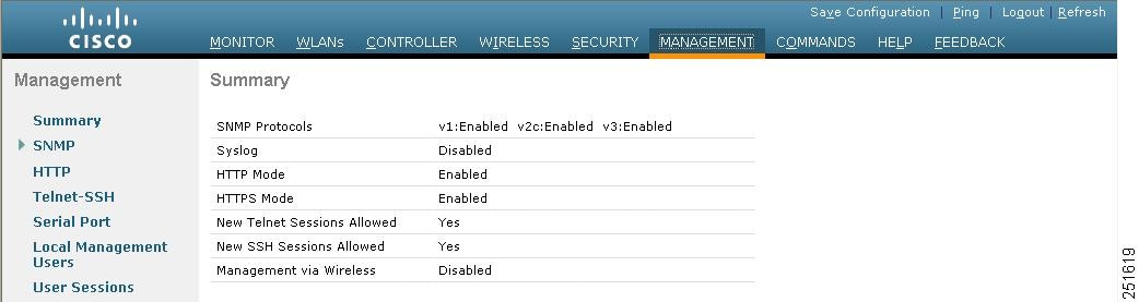
This page shows whether additional Telnet and SSH sessions are permitted.
Using the CLI to Configure Telnet and SSH Sessions
Using the controller CLI, follow these steps to configure Telnet and SSH sessions.
Step 1 To allow or disallow new Telnet sessions on the controller, enter this command:
config network telnet { enable | disable }
The default value is disabled.
Step 2 To allow or disallow new SSH sessions on the controller, enter this command:
config network ssh { enable | disable }
Step 3 To specify the number of minutes that a Telnet session is allowed to remain inactive before being terminated, enter this command:
config sessions timeout timeout
where timeout is a value between 0 and 160 minutes (inclusive). The default value is 5 minutes. A value of 0 indicates no timeout.
Step 4 To specify the number of simultaneous Telnet sessions allowed, enter this command:
config sessions maxsessions session_num
where session_num is a value between 0 and 5 (inclusive). The default value is 5 sessions.
Step 5 To save your changes, enter this command:
Step 6 To see the Telnet and SSH configuration settings, enter this command:
Information similar to the following appears:
Step 7 To see the Telnet session configuration settings, enter this command:
Information similar to the following appears:
Step 8 To see all active Telnet sessions, enter this command:
Information similar to the following appears:
Step 9 If you ever want to close all active Telnet sessions or a specific Telnet session, enter this command:
config loginsession close { all | session_id }
Enabling Wireless Connections to the GUI and CLI
You can monitor and configure controllers using a wireless client. This feature is supported for all management tasks except uploads from and downloads to the controller.
Before you can open the GUI or the CLI from a wireless client device, you must configure the controller to allow the connection. Follow these steps to enable wireless connections to the GUI or CLI.
Step 2 Enter config network mgmt-via-wireless enable.
Step 3 Use a wireless client to associate to a lightweight access point connected to the controller.
Step 4 On the wireless client, open a Telnet session to the controller, or browse to the controller GUI.

Tip To use the controller GUI to enable wireless connections, choose Management > Mgmt Via Wireless page and check the Enable Controller Management to be accessible from Wireless Clients check box.
 Feedback