-
Installation Guide for Cisco Unity with IBM Lotus Domino (Without Failover), Release 4.0(5) and Later
-
Index
-
Preface
-
Overview of Mandatory Tasks for Installing Cisco Unity
-
Preparing for the Installation
-
Setting Up the Hardware
-
Installing the Operating System
-
Customizing the Cisco Unity Platform
-
Setting Up Domino and Installing Lotus Notes
-
Creating Accounts for the Installation and Setting Rights and Permissions
-
Installing and Configuring Cisco Unity Software
-
Installing Optional Software
-
Setting Up Authentication for the Cisco Unity Administrator
-
Appendix: Voice Cards and PIMG Units
-
Appendix: Exiting and Starting the Cisco Unity Software and Server
-
Appendix: Manual Installation Procedures for Software Installed by the Cisco Unity System Preparation Assistant During a New Installation
-
 Feedback
Table Of Contents
Intel Dialogic D/41EPCI, D/41JCT-LS, and D/41JCT-Euro
Intel Dialogic D/120JCT-LS and D/120JCT-Euro
Intel NetStructure PBX-IP Media Gateway (PIMG)
Removing Intel Dialogic Voice Card Software
Determining the Current Settings for the Quiet Parameter and Other Parameters
Removing the Intel Dialogic Voice Card Software
Resetting the Quiet Parameter and Other Parameters
Voice Cards and PIMG Units
This appendix contains the following sections:
•
Intel Dialogic D/41EPCI, D/41JCT-LS, and D/41JCT-Euro
•
•
•
Intel Dialogic D/41EPCI, D/41JCT-LS, and D/41JCT-Euro
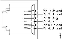
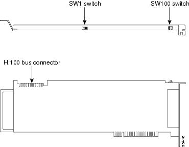
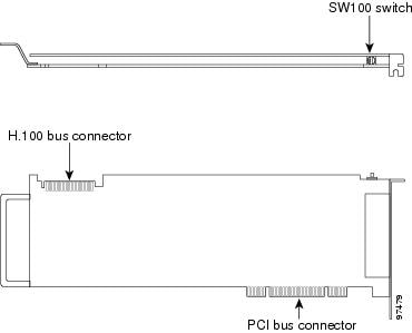
The D/41EPCI, D/41JCT-LS, and D/41JCT-Euro voice cards provide four independent voice-processing ports in a single PCI slot. The cards connect four phone-line interface circuits directly to analog loop-start lines by using RJ-11 connectors.
If you are installing cards that have H.100 connectors, you need an H.100 cable that has at least as many connectors as you have cards (you must connect all cards by using a single cable) but no more than five extra connectors.
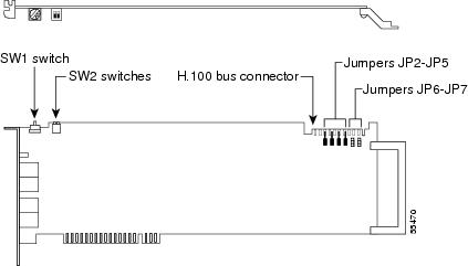
Figure A-1 D/41EPCI Top and Side Views
Figure A-2 D/41JCT-LS, and D/41JCT-Euro Top and Side Views
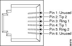
Figure A-3 D/41EPCI, D/41JCT-LS, and D/41JCT-Euro Connection Pinouts and Backplate
Hardware Settings
To Set the D/41EPCI Card Switches and Jumpers
Step 1
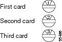
Each Intel Dialogic card in the Cisco Unity server or expansion chassis must have a unique value, starting with 1 and continuing in sequence on subsequent cards. For example, set the rotary switch on the first three voice cards as shown below. This is also the order in which you install the cards in the server or expansion chassis.
Step 2
Step 3
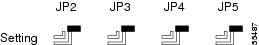
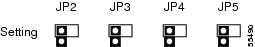
Set jumpers JP2 through JP5 to Off (Figure A-4) on
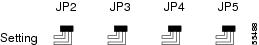
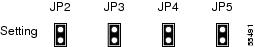
the card.Set jumpers JP2 through JP5 to On (Figure A-5) on
both cards.Set jumpers JP2 through JP5 to On (Figure A-5) on the first and last cards.
Set jumpers JP2 through JP5 to Off (Figure A-4) on all other cards.
Figure A-4 D/41EPCI Jumpers JP2 Through JP 5: Off
Figure A-5 D/41EPCI Jumpers JP2 Through JP 5: On
Step 4
To Set the D/41JCT-LS and D/41JCT-Euro Card Switches and Jumpers
Step 1
Each Intel Dialogic card in the Cisco Unity server or expansion chassis must have a unique value, starting with 1 and continuing in sequence on subsequent cards. For example, set the rotary switch on the first three voice cards as shown below. This is also the order in which you install the cards in the Cisco Unity server or expansion chassis.
Step 2
Step 3
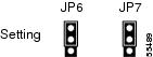
Jumper JP1 is reserved. Do not install a shunt across the pins of JP1.
Set jumper JP2 according to the number of D/41JCT-LS or D/41JCT-EURO cards in the server or expansion chassis:
Intel Dialogic D/120JCT-LS and D/120JCT-Euro
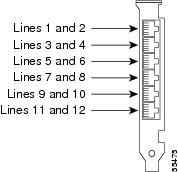
The D/120JCT-LS and D/120JCT-Euro voice cards each provide 12 channels of call-processing and loop-start interfaces in a single PCI slot. The D/120JCT-LS is used in North America, South America, and Japan, and the D/120JCT-Euro is used in Europe, Australia, and New Zealand. The cards connect 12 analog loop-start phone lines to 12 onboard call-processing resources by using RJ-14 connectors.
We recommend using the newer Revision 2 Universal (3.3Vdc or 5Vdc dual voltage) PCI versions of the Intel Dialogic D/120JCT-LS and the D/120JCT-Euro cards, rather than the older single-bus voltage (5Vdc) versions of the cards.
Note that older Revision 1 LS cards are still supported for use with Cisco Unity version 4.0(x), but they cannot be ordered for new Cisco Unity version 4.0(x) installations. In addition, the older LS cards can be used only when they are appropriate for the available slots in the Cisco Unity server or expansion chassis.
If you are installing cards that have H.100 connectors, you need an H.100 cable that has at least as many connectors as you have cards (you must connect all cards by using a single cable) but no more than five extra connectors.
You may need to attach or remove the slot retainer bracket that ships with the card, depending on the mechanical configuration of the Cisco Unity server or expansion chassis.
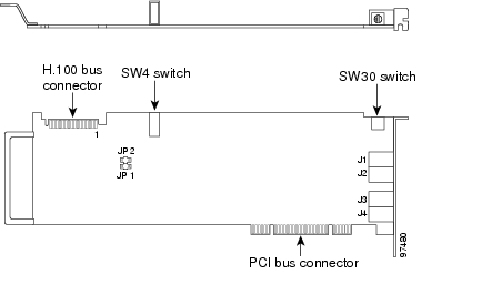
Figure A-6 D/120JCT-LS and D/120JCT-Euro Rev 1 (Conventional PCI) Top and Side Views
Figure A-7 D/120JCT-LS and D/120JCT-Euro Rev 2 (uPCI) Top and Side Views
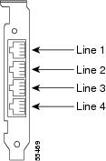
Figure A-8 D/120JCT-LS and D/120JCT-Euro Connection Pinouts and Backplate
Hardware Settings
To Set the D/120JCT-LS and D/120JCT-Euro Card Switches
Step 1
Each Intel Dialogic card in the Cisco Unity server or expansion chassis must have a unique value, starting with 1 and continuing in sequence on subsequent cards. For example, set the rotary switch on the first three voice cards as shown below. This is also the order in which you install the cards in the server.
Step 2
Software Settings
Do the following procedure only if the Cisco Unity server contains D/120JCT-Euro voice cards. There are no software settings for D/120JCT-LS voice cards.
To Select the Country for D/120JCT-Euro Voice Cards
Step 1
Step 2
Step 3
Step 4
Step 5
Step 6
Step 7
Step 8
Step 9
Step 10
Step 11
Step 12
Step 13
Step 14
Step 15
Step 16
Intel Dialogic D/240PCI-T1
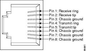
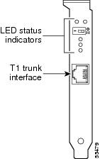
The Dialogic D/240PCI-T1 voice card provides one T1 span with 24 channels of voice processing in a single PCI slot. The card connects directly to a channel-service unit, digital-service unit, or to other phone-network terminating equipment by using an RJ-48C connector.
If you are installing cards that have H.100 connectors, you need an H.100 cable that has at least as many connectors as you have cards (you must connect all cards by using a single cable) but no more than five extra connectors.
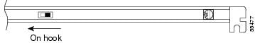
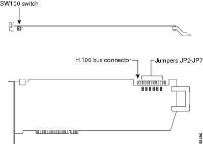
Figure A-9 D/240PCI-T1 Top and Side Views
Figure A-10 D/240PCI-T1 Connection Pinouts and Backplate
Hardware Settings
To Set the D/240PCI-T1 Card Switches and Jumpers
Step 1
Each Intel Dialogic card in the Cisco Unity server or expansion chassis must have a unique value, starting with 1 and continuing in sequence on subsequent cards. For example, set the rotary switch on the first three voice cards as shown below. This is also the order in which you install the cards in the server.
Step 2
Set jumpers JP2 through JP5 to Off (Figure A-11) on
the card.Set jumpers JP2 through JP5 to On (Figure A-12) on
both cards.Set jumpers JP2 through JP5 to On (Figure A-12) on the first and last cards.
Set jumpers JP2 through JP5 to Off (Figure A-11) on all other cards.
Figure A-11 D/240PCI-T1 Jumpers JP2 Through JP 5: Off
Figure A-12 D/240PCI-T1 Jumpers JP2 Through JP 5: On
Step 3
Software Settings
For a D/240PCI-T1 voice card, set the protocol manually after the Cisco Unity Setup program is finished.
To Set the D/240PCI-T1 Protocol
Step 1
Step 2
Step 3
Step 4
Step 5
Step 6
Step 7
Step 8
Step 9
Step 10
Step 11
Step 12
Step 13
Step 14
Intel NetStructure PBX-IP Media Gateway (PIMG)
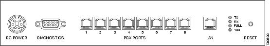
The Intel NetStructure PBX-IP Media Gateway (PIMG) units each connect to eight ports from a circuit-switched phone system (either analog or digital phone lines, depending on the model of the PIMG unit). The PIMG units communicate with the Cisco Unity server through the LAN by using Session Initiation Protocol (SIP).
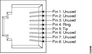
The lines from the phone system attach to a PIMG unit with RJ-45 connectors, though it is possible to use RJ-11 connectors on these lines instead.
Figure A-13 PIMG Unit Connection Pinout and Port Connections
We recommend that the lines connect to the ports on the PIMG units in the same order as the ports on the phone system. For example, the first phone system port connects to the first port on the PIMG unit, the second phone system port connects to the second port on the PIMG unit, and so on.
Software Settings
Instructions for configuring PIMG units for integrating a phone system with Cisco Unity are found in the applicable Cisco Unity integration guide, available at http://www.cisco.com/en/US/products/sw/voicesw/ps2237/products_installation_and_configuration_guides_list.html.
Removing Intel Dialogic Voice Card Software
Determining the Current Settings for the Quiet Parameter and Other Parameters
When the quiet parameter and any other parameters have been set to a value other than the default, the settings will be lost when you remove the Intel Dialogic software. Write down the current values of the parameters so you can restore the values after you reinstall the software. If the parameter-file value is blank, the Intel Dialogic default settings are being used, and you do not need to reset any parameter values when you reinstall the software.
To Determine the Current Settings for the Quiet Parameter and Other Parameters
Step 1
Step 2
Step 3
Step 4
Step 5
The tree-structured list contains an entry for each Intel Dialogic card installed in the server.
Step 6
Step 7
Step 8
Step 9
Step 10
If the Value field is blank, the Intel Dialogic default settings are being used.
Step 11
Step 12
Removing the Intel Dialogic Voice Card Software
The following procedure may differ slightly for earlier versions of Cisco Unity, which used an earlier version of Dialogic Configuration Manager.
To Remove Intel Dialogic Voice Card Software
Step 1
Step 2
Step 3
Step 4
Step 5
Dialogic Configuration Manager may display an error message about not detecting devices. This error is harmless. Click OK.
Step 6
Step 7
Step 8
Step 9
Step 10
Step 11
Step 12
Step 13
Step 14
Step 15
Step 16
Step 17
Step 18
Step 19
Step 20
Step 21
Step 22
Step 23
Step 24
Caution
Step 25
Step 26
Step 27
Step 28
Step 29
If you are prompted to delete shared files, click No to All.
Step 30
Step 31
Step 32
Step 33
Resetting the Quiet Parameter and Other Parameters
After you reinstall Intel Dialogic voice card software, do the following procedure to reset the quiet parameter to the value you identified in the "Determining the Current Settings for the Quiet Parameter and Other Parameters" section.
To Reset the Quiet Parameter and Other Parameters
Step 1
Step 2
Step 3
Step 4
Step 5
The tree-structured list contains an entry for each Intel Dialogic card installed in the server.
Step 6
Step 7
Step 8
Step 9
Step 10
(For example, for the quiet parameter, enter quiet<XX>.prm, where XX = the -dBm level of the desired quiet parameter file. The recommended setting for Cisco Unity is 50.)
Step 11
Step 12
Step 13