Feedback
Table Of Contents
Introduction to Monitoring Cisco Unity Performance
Determining Performance Expectations
Performance Monitoring in an On-Box vs. Off-Box Message Store Environment
Permissions Required for Performance Monitoring
Configuring Cisco Unity Performance Information Tools
Configuring Cisco Unity Performance Information and Diagnostics (CUPID)
Configuring Microsoft Performance Monitor
Performance Monitor Configuration for a Cisco Unity Server
Performance Monitor Configuration for an Off-Box Cisco Unity Message Store Server
Administrative Monitoring Guidelines for Cisco Unity Performance
Task List: Preparing for Performance Testing
Collecting the System Test Information
Analyzing Performance Test Results
Required System Performance Counters
General System Performance Counters
Cisco Unity Server Performance Counters
Cisco Unity Message Store Performance Counters
Performance Monitoring
Introduction to Monitoring Cisco Unity Performance
Performance data is valuable for troubleshooting, predicting future system requirements, and administrative monitoring of the Cisco Unity messaging infrastructure. Performance information also plays a large part in determining the health and scalability of a Cisco Unity deployment.
Cisco Unity is dependent on the messaging subsystem, which is Lotus Domino. If the messaging subsystem fails, goes off line, performs poorly, or otherwise becomes unavailable, unified messaging functionality and the performance of Cisco Unity suffers. Because of this dependency on the messaging infrastructure, the message store architecture and the design of a Cisco Unity deployment are two of the most important factors to consider for performance impact on the user experience.
Defining Performance
In client/server computing, performance is the speed, efficiency, and ultimately the responsiveness of computer operations. Traffic flow is a good analogy for computing because the computing system logically compares to a traffic grid. Moving a vehicle from one end of a city to the other presents particular challenges to transportation efficiency, as does moving data from one end of a computer system to another. Issues such as timing, speed, load patterns, queuing, and the efficiency of the system all affect the movement of data.
A baseline is the observed and recorded measurement of performance against which comparisons are made. Baselines are only useful if they are recorded and then actively compared against past or future measurements, for example:
•
Capturing the performance characteristics of a system in order to troubleshoot a particular performance problem.
•
•
At the application level, computer performance is usually divided into four performance elements:
•
•
•
•
There are other factors that can introduce performance degradation, such as heat, electromagnetic radiation, and inferior components, but they are for consideration at a lower level of computer design and implementation than we are concerned with here.
Determining Performance Expectations
In a unified messaging deployment, user expectations for e-mail and voice messages may not be the same. E-mail messaging involves the transmission of text or images within electronic mail that is not entirely time-dependent. An acceptable rate of delivery may range from a few seconds to a few minutes. In contrast, voice messaging involves the real-time transmission of audio information to a user and demands a lower occurrence of delay or latency. What qualifies as acceptable performance can vary from site to site, and from user to user. Determining what is required for performance monitoring equates to determining and communicating what is acceptable performance.
Sites need to level user assumptions and expectations of messaging performance against the realities of business demands. A rock-solid design and implementation plan for the messaging infrastructure is usually the best defense against unmet expectations, but problems do still occur. Some common reasons for performance issues and unmet expectations include:
•
•
A good measure of how well expectations are being met is to simply ask if the solution provides the service requested. From there, the next steps are adding accessibility, speed of response, and other site-specific factors. Bear in mind that these questions are some of the most difficult to answer because they are subjective:
•
•
•
Performance Monitoring in an On-Box vs. Off-Box Message Store Environment
In the Cisco Unity architecture, it is not required, nor in some configurations is it optimal or even supported, to have the Cisco Unity message store on the same physical server hardware (on-box) as the Cisco Unity server that conducts voice call processing. (What is commonly referred to as an off-box message store configuration is a Cisco Unity system that stores subscriber messages on a separate physical server or servers.) An off-box configuration can present a significant performance benefit by distributing the performance resources required across multiple systems.
As with any implementation design, there are caveats to the off-box configuration. For example, the network on which the communications between Cisco Unity and the message store occur can become a bottleneck or point of failure. It is therefore necessary to monitor all of the servers and message stores in use by Cisco Unity for performance issues. To assist in this task, the Cisco Unified Performance Information and Diagnostics (CUPID) tool, Microsoft Performance Monitor, and Microsoft Management Console (MMC) each allow single-point remote administration of multiple servers.
Permissions Required for Performance Monitoring
Administrative privileges are required for each of the servers to be monitored. Use an administrative account, or assign the following minimum permissions to a specific account or group responsible for performance monitoring:
•
•
•
•
•
It is possible and sometimes necessary to remotely monitor a target system with the Performance Monitor. However, issues of service rights for the Performance Logs and Alerts service, and problems with network connectivity, can interfere with testing. Therefore, we recommend that performance tests be run locally on the target machine whenever possible.
Configuring the Network Provider Monitor on the Cisco Unity Server and Cisco Unity Message Store Servers
To capture network traffic information, it may be necessary to install the Network Monitor Provider. Because of the performance impact of the Network Monitor Provider, we recommend collecting data for short intervals during periods of off-peak system usage.
To Install the Network Monitor Provider
Step 1
Step 2
Step 3
Step 4
Step 5
Step 6
Configuring Cisco Unity Performance Information Tools
Running the CUPID utility or the Performance Monitor on the local server is an active, semi-intrusive form of monitoring. However, the effect is mitigated by the large sample interval and relatively small application footprint of CUPID or the Performance Monitor. The overhead or load impact of the monitoring tools should be minimal and not observable in the analysis of the results.
We recommend that the performance log data be captured to a physical disk or logical volume that does not hold either the Cisco Unity executables or the data from Domino or SQL Server, and that has sufficient space available for collection of diagnostic trace and log data. Doing so will reduce throughput issues on systems with high traffic.
Configuring Cisco Unity Performance Information and Diagnostics (CUPID)
CUPID is a performance and diagnostic information collection utility for Windows 2000. At its core, CUPID is an NT service that communicates to the performance subsystem of the Windows Operating System, and collects data based on the counters specified in a XML configuration file. CUPID is available in Tools Depot for Cisco Unity version 4.0(3) and later. Updates are periodically made available for download at http://www.CiscoUnityTools.com.
A configuration document used for CUPID consists of an XML document that implements a single CounterSet element with several Counter child elements that define the counters to collect. The configuration files included with the CUPID installation represent the latest recommended performance counters to collect when running a performance test. By default, CUPID will look for a default configuration file at: C:\%SYSTEMROOT%\System32\Cupid_default.xml. If this file is not available, another configuration file will need to be specified. Review the configuration document for the specific needs of the system under test. For example, additional counters may be needed to monitor a third party backup or antivirus solution in addition to normal messaging activity.
Note that remote monitoring of Cisco Unity or Cisco Unity message store performance with CUPID is not supported. Refer to the CUPID online Help for more information.
To Change CUPID Configuration Settings
Step 1
Step 2
Step 3
Step 4
To Automatically Start Collection of CUPID Performance Information on System Startup
Step 1
Step 2
Step 3
Step 4
Configuring Microsoft Performance Monitor
The Microsoft Management Console (MMC), of which the Performance Monitor is a pair of components, is a collection of modular administration tools that allows a centralized interface for many different maintenance and managerial functions on a local or remote system. The MMC is flexible enough to allow a single point of administration, and to allow custom interfaces or consoles to accomplish common tasks.
When working with Cisco Unity, an administrator may need to access elements of the MMC that deal with Active Directory Users and Computers, or SQL servers. However, when assessing Cisco Unity performance, the Performance Monitor, which is comprised of the System Monitor and the Performance Logs and Alerts controls, is the preferred tool for overall analysis.
The System Monitor is an ActiveX control component that can be added to a MMC console or embedded within a web page or similar document. The authored console version of the Performance Monitor contains both the System Monitor and the Performance Logs and Alerts control. A stand-alone executable version is also available from the Windows 2000 Resource Kit.
Note that some elements of Cisco Unity performance may be difficult or impossible to measure through the use of the Performance Monitor alone. For example, Message Waiting Indication (MWI) response time, message delivery speed, and directory/addressing lookup delays are difficult performance elements to measure. Because certain operations depend on the distributed elements of a larger system (such as network bandwidth, remote message store server performance, and voice board or integration performance), the Performance Monitor may only be able to show a portion of a particular performance issue. There may be additional hardware or software tools (such as a network packet analyzer) and methods required to obtain the performance information necessary to characterize the complete Cisco Unity implementation.
To Start the Performance Monitor as an Authored Console
Step 1
To Embed Performance Monitoring Capability in an MMC Console
Step 1
Step 2
Step 3
Step 4
Step 5
Step 6
Step 7
Step 8
Step 9
Step 10
Step 11
Step 12
Step 13
To Embed Performance Monitoring Capability in a Document
Step 1
Step 2
Step 3
Step 4
Performance Monitor Configuration for a Cisco Unity Server
Configuring the Microsoft Performance Monitor for use with Cisco Unity involves adding the applicable performance counters to a counter log. For a list of counters that need to be collected to begin the performance monitoring process, see Table 5-1. Additional counters may be necessary to refine the specific goals of a particular performance investigation, but the counters listed in Table 5-1 are a good start.
To Manually Configure the Performance Monitor for Real-time Performance Monitoring of a Cisco Unity Server
Step 1
Step 2
Step 3
Step 4
Step 5
Step 6
To Manually Configure the Performance Monitor for Data Collection (Performance Monitoring Log)
Step 1
Step 2
Step 3
Step 4
Step 5
Step 6
Step 7
Step 8
Note
Step 9
Step 10
Step 11
Performance Monitor Configuration for an Off-Box Cisco Unity Message Store Server
Usually, when you are monitoring an off-box Cisco Unity message store server, no local Cisco Unity processes need to be monitored. Instead, only the operating system and the message store resources need to be monitored.
The main process that needs to be monitored is the Information Store (Store.exe) that homes all of the databases on the Cisco Unity server. Usage of Store.exe is directly proportional to the number of users on the Cisco Unity system, the size of each database, and the number of databases and storage groups.
To Manually Configure the Performance Monitor for Real-Time Performance Monitoring of an Off-Box Message Store Server
Step 1
Step 2
Step 3
Step 4
Step 5
Step 6
To Manually Configure the Performance Monitor for Data Collection Performance Monitoring
Step 1
Step 2
Step 3
Step 4
Step 5
Step 6
Step 7
Step 8
Step 9
Administrative Monitoring Guidelines for Cisco Unity Performance
One of the key elements of a healthy and scalable messaging system is the active monitoring of the system by the administration ultimately responsible for its success. A good method to achieve this is to implement a performance maintenance policy that is supported throughout the deployment of each server in use by Cisco Unity. It is also important to document all necessary performance activities for purposes of scalability planning, capacity audits, and survivability of procedures through personnel changes.
We recommend creating a thorough plan that includes the following tasks:
1.
2.
You may decide to use a single application, such as CUPID or the Performance Monitor, to monitor messaging system performance, or you may choose to incorporate the monitoring of Cisco Unity and the messaging system into an existing administrative monitoring infrastructure. Third party monitoring solutions (for example, that use SNMP or WMI) are also available to monitor Cisco Unity and other Cisco products in a large enterprise environment.
3.
This includes specifying monitoring timeframes, and deciding when collected logs will be cycled and reviewed. For example, a small company may not have personnel to monitor the messaging system on weekends and every day of the week. Therefore, this company could decide to create a snapshot of performance on Monday mornings, at the time of their busiest call volume.
4.
A baseline for performance maintenance is crucial for the detection of deviations from normal business operations. Normal business operations should be defined as the average measurements from a typical business day. Depending upon the business solution being monitored, the measurements could be gathered for an 8-hour core workday, for all daylight hours, for a 24-hour schedule, or for specific shift hours.
5.
6.
7.
8.
Determine which data needs to be archived. Additionally, consider the storage location and archival time limit for the information.
9.
a.
b.
c.
d.
Performance Testing
A performance test can be useful in evaluating whether situations are appropriately handled by the Cisco Unity server or the Cisco Unity message store. For example, you may want to evaluate the performance of the Cisco Unity server under a significant load from web-based clients, or when extremely large numbers of users initially enroll.
Performance Testing Process
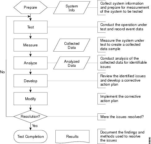
The performance testing process is similar to the scientific method of analysis in that the repeatability of findings is important to an understanding of a problem. In most cases, the performance testing process is cyclical. Every measurement session has the potential to spawn new questions or avenues of approach to the initial question. The cycle may have to be repeated numerous times before the operation under test is fully understood.
We recommend the performance testing process shown in Figure 5-1.
Figure 5-1 Recommended Performance Testing Process
Preparing to Conduct the Test
The following "Task List: Preparing for Performance Testing" details the high-level tasks you need to do in preparation for performance testing. Also see the following procedures:
•
•
•
Task List: Preparing for Performance Testing
1.
Due to the complex architecture of Cisco Unity, it is always a good idea to narrow the focus of the test, if possible. Performance dependencies between system components can quickly make an investigation very complex.
2.
For some deployments, this will be the primary concern for any performance consideration. For example, Maximum expected delays or system performance thresholds can be established with user input.
3.
For example, you may want to monitor Cisco Unity performance to investigate a slow interactive response on an existing deployment, or to validate and gather baseline measurements of an existing message store infrastructure in preparation for a Cisco Unity installation.
4.
If a single feature is to be monitored, it may be possible to reduce the amount of monitoring necessary, while system level monitoring may require a broad range of performance data points. Is a particular area suspected as a bottleneck? If there has been a change to the Cisco Unity system, such as the addition of new hardware or software, and the change seems to have affected performance, the specific area should be monitored. Keep in mind that understanding the system performance as a whole has value, but if the purpose it to identify the cause of a particular bottleneck, narrowing the scope of the investigation is critical.
5.
Specifying a preset amount of time for measurement helps to frame the problem under investigation. For example, if users report slow access times when logging into Cisco Unity on Monday mornings, but not Tuesday mornings, plan for a sample taken from midnight on Sunday until the following Tuesday at midnight. With this information, data from Monday can be compared to the data from Tuesday, within the same set of results. Also, by recording start, stop, and duration sample times independently of the Performance Logs, issues of incorrect, unsynchronized, or remote system times can be avoided.
6.
Because performance tests should be conducted against the target system as that system is normally operated or configured, we recommend that Cisco Unity diagnostic traces be disabled for most performance testing, unless you are instructed otherwise by Cisco TAC.
To Configure Diagnostic Tracing in the Cisco Unity Diagnostics Tool
As a best practice, all diagnostic traces should be disabled except those that are directly related to the performance investigation, or as advised by Cisco TAC.
Step 1
Step 2
If a performance problem is suspected as the cause of a port lockup, we recommend you select the System Locks macro trace.
Cisco TAC may request that additional tools, diagnostics, and procedures be executed on the target system, any of which may have an associated performance impact.
To Start the Performance Monitoring Tool
Step 1
Step 2
To Start a Performance Monitor Counter Log
Step 1
Step 2
Step 3
Conducting the Test
Depending on the conditions that are being reproduced for the performance test, conducting the test can involve a variety of activities varying in duration. The goal can be as specific as understanding the memory utilization of a single application process, or as broad as gaining an understanding of overall system performance.
Upon completion of the performance test, it is important to stop the collection of performance data to reduce any operational overhead and prevent unneeded data from being entered into the performance log. Do the following "To Stop the Test" procedure.
Note
To Stop the Test
Step 1
Step 2
Collecting the Recorded Data
Locate the data file created during the monitored session. You will analyze the collected data by using the Performance Monitor or a suitable spreadsheet application, such as Microsoft Excel. CUPID logs can be opened in both Microsoft Performance Monitor and Microsoft Excel.
To Open a Captured Performance Log File in Performance Monitor
Step 1
Step 2
Step 3
Step 4
Step 5
Step 6
The default location for Performance Monitor logs is C:\PerfLogs.
Step 7
To Open a Captured Performance Log File in Microsoft Excel
Step 1
Step 2
Step 3
The first row in the file represents the available counters that were tracked by the Performance Monitor on the target system and the first column represents the time of the sample. Each row entry constitutes a sample taken on the system and this number will vary depending on the sampling interval.
Collecting the System Test Information
Collecting information about the system under test is just as important as gathering the performance data from the system. In most cases, it is necessary to run the Gather Cisco Unity System Information (GUSI) tool, available in Tools Depot, and to run Microsoft WinMSD on both the Cisco Unity Server and the Cisco Unity message store.
Note that both of these tools can impact system performance. Schedule the collection of system test information during a maintenance window, if possible.
To Run the Gather Cisco Unity System Information (GUSI) Tool
Step 1
Step 2
Step 3
Step 4
Step 5
To Run WinMSD
Step 1
Step 2
Step 3
Step 4
Note
To Collect Event Logs
Step 1
Step 2
Step 3
Step 4
Step 5
Step 6
Analyzing Performance Test Results
Analysis of collected performance test results is an extremely important part of understanding the overall performance of Cisco Unity. The following guidelines allow you to validate, understand, and evaluate the information generated from a performance test.
To validate collected data, open the captured log file in the Performance Monitor or a spreadsheet application and verify that data has actually been recorded. The columns within the open document will contain data in the sequence in which the sample was taken (for most entries.) Columns that are blank represent objects or counters that were non-existent on the target system during the collected sample time.
External, user-discernible indicators of poor Cisco Unity system performance include:
•
•
•
•
•
•
Note that some of these indicators are subjective, especially those focusing on the amounts of silence or delay experienced by a user during the Cisco Unity conversation.
There are also internal, or administratively measurable, indicators of poor Cisco Unity system performance:
•
•
•
•
•
Key objects for the initial assessment of a target system are the Memory, Process, Processor, Telephony, and Cisco Unity performance objects. These objects contain many of the core data points that are helpful in determining system activity. For example, when using the Telephony object, the Current Incoming Calls and Current Outgoing Calls counters describe the call activity into and out of the Cisco Unity server, and thus are a good indication of average voice session traffic.
To obtain information such as call duration, call forwarding, and phone system transfers into Cisco Unity, use the Port Usage Analyzer tool (available in Tools Depot), as well as external sources of information such as phone system reports or call detail records. This data can be used in conjunction with the data collected from the Cisco Unity system to form a complete picture of phone system activity during the monitored period.
At a minimum, the following phone system information should be collected:
•
•
•
Session traffic into the system from web clients should also be collected. This activity can be obtained through the use of the Web Services object, and allows you to track Cisco Unity Assistant and Cisco Unity Administrator logons and connections.
Performance Counters
To monitor physical disk performance information, it is necessary to enable the disk performance counters on the server. With Windows 2000, the physical disk performance counters are enabled by default. In Cisco Unity version 4.0(3) and later, the performance counters for measuring Cisco Unity data points are also enabled by default.
Required System Performance Counters
The counters in Table 5-1 should be collected from any Cisco Unity server or Cisco Unity message store performance monitoring session.
General System Performance Counters
Table 5-2 shows counters that are applicable to both the Cisco Unity server and the Cisco Unity message store, including their recommended safe values.
Cisco Unity Server Performance Counters
Table 5-3 shows important Cisco Unity server counters and their recommended safe values.
Cisco Unity Message Store Performance Counters
Table 5-4 shows important Cisco Unity message store counters and their recommended safe values.