-
Cisco Unity Failover Configuration and Administration Guide (With Microsoft Exchange), Release 4.x
-
Index
-
Preface
-
Configuring Cisco Unity Failover
-
Tasks Required When Failover or Failback Occurs
-
Monitoring and Maintaining Cisco Unity Failover
-
About Cisco Unity Failover
-
Appendix: Exiting and Starting the Cisco Unity Software and Server\r\n
-
Appendix: Line Connections Between the Phone System and the Cisco Unity Servers
-
Appendix: Behavior of Cisco Unity Failover During Outages of Network Components
-
 Feedback
Table Of Contents
Line Connections Between the Phone System and the Cisco Unity Servers
Analog Voice Line Connections for Failover
Connections with D/41-Series Voice Cards
Connections with D/120-Series Voice Cards
Serial Data Cable Connections for Failover
Pinouts for the Serial Data Cables
Serial Cables Between the Phone System and the Data Splitter
Serial Cables Between the Data Splitter and the Cisco Unity Servers
Connections for the Serial Data Cables
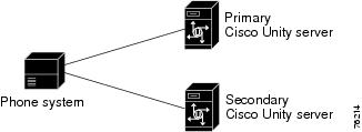
Line Connections Between the Phone System and the Cisco Unity Servers
This appendix describes the line connections between a circuit-switched phone system and the voice cards on the primary and secondary Cisco Unity servers.
Note
For connections involving Cisco CallManager or SIP proxy servers, refer to the applicable Cisco Unity integration guide.
Integrations using PIMG units are not supported with Cisco Unity failover.This appendix contains the following sections:
•
•
Analog Voice Line Connections for Failover
Circuit-switched phone systems typically have 25-pair or 32-pair cables to provide analog voice connections. It is common that the cable is broken into individual lines that may attach to a punchdown cross-connect block (for example, 66-Type), or the cable may terminate with RJ-11 or RJ-14 connectors to accept analog voice lines.
A punchdown cross-connect block or line splitters may be used to split the analog lines. It is possible to use these devices in combination to manage and split the lines.
Note
Requirements
The following components are required for common configurations:
•
•
–
–
•
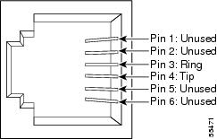
Figure B-1 RJ-11 Connector Pinout
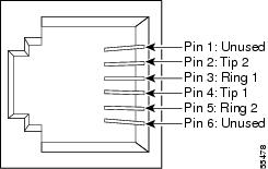
Figure B-2 RJ-14 Connector Pinout
Connections with D/41-Series Voice Cards
The following figures illustrate common configurations:
•
•
•
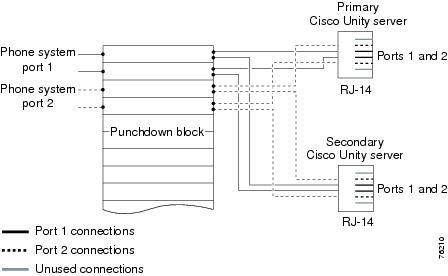
Figure B-3 Connections from the Phone System Through a Punchdown Block to D/41-Series Voice Cards
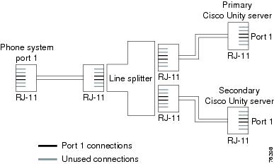
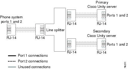
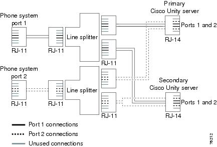
Figure B-4 Connections for an RJ-11 Connector from the Phone System to D/41-Series Voice Cards
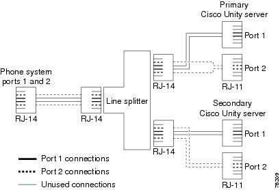
Figure B-5 Connections from an RJ-14 Connector on the Phone System to D/41-Series Voice Cards
Connections with D/120-Series Voice Cards
The following figures illustrate common configurations:
•
•
•
Figure B-6 Connections from the Phone System Through a Punchdown Block to D/120-Series Voice Cards
Figure B-7 Connections for an RJ-14 Connector from the Phone System to D/120-Series Voice Cards
Figure B-8 Connections for an RJ-11 Connector from the Phone System to D/120-Series Voice Cards
Serial Data Cable Connections for Failover
Only serial integrations (for example, SMDI, MCI, or PBXLink) use RS-232 serial data cables.
Connecting RS-232 serial cables between a circuit-switched phone system and the primary and secondary Cisco Unity servers varies depending on the number of serial ports the phone system has.
Requirements
The following components are required for phone systems with only one serial port:
•
•
The following components are required for phone systems with multiple serial ports:
•
Pinouts for the Serial Data Cables
The pinouts for the serial cables depend on whether the serial port on the phone system acts as data circuit-terminating equipment (DCE—it does not originate signals but acts as a modem) or as data terminal equipment (DTE—it originates signals).
Serial Cables Between the Phone System and the Data Splitter
If the serial port on the phone system acts as DCE, use an RS-232 serial cable with the pinout shown in Table B-1 for the data link between the phone system and the data splitter. The cable creates a DCE-to-DTE connection.
If the serial port on the phone system acts as DTE, use a null modem serial cable with the pinout shown in Table B-2 for the data link between the phone system and the data splitter. The cable creates a DTE-to-DTE connection.
Phone systems with multiple serial ports use the applicable pinout for the two serial cables connecting the phone system to the Cisco Unity servers.
Serial Cables Between the Data Splitter and the Cisco Unity Servers
The two serial cables between the data splitter and the primary and secondary Cisco Unity servers use wiring as shown in Table B-3.
Table B-3 Serial Cable Wiring Between the Data Splitter and the Cisco Unity Servers
1
1
2
2
3
3
4
4
5
5
6
6
7
7
8
8
9
9
Connections for the Serial Data Cables
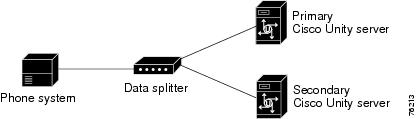
Figure B-9 shows the connections between the serial port on a phone system that has only one serial port to the serial ports on the primary and secondary Cisco Unity servers. Figure B-10 shows the connections between the serial ports on a phone system that has two serial ports to the serial ports on the Cisco Unity servers.
Note that the following figures do not show the analog voice lines, which are described in the "Analog Voice Line Connections for Failover" section.
Figure B-9 Serial Cable Connections from a Single Serial Port on the Phone System to the Serial Ports on the Cisco Unity Servers
Figure B-10 Serial Cable Connections from Multiple Serial Ports on the Phone System to the Serial Ports on the Cisco Unity Servers