NEC NEAX 2000 with Serial MCI Integration Guide for Cisco Unity 3.1(1)
NEC NEAX 2000 with Serial MCI Integration

Table Of Contents

NEC NEAX 2000 with Serial MCI Integration

Integration Overview

Integration Steps

Requirements

Integration Description

Integration Features

Programming the Phone System

Configuring Cisco Unity for the Integration

Testing the Integration

Integrating a Cisco Unity Failover (Secondary) Server

Requirements

Integration Description

Setting Up the Failover (Secondary) Server


NEC NEAX 2000 with Serial MCI Integration


Integration Overview

Before performing the following integration steps, confirm that the Cisco Unity server is ready for the integration by completing the appropriate tasks in the Cisco Unity Installation Guide.

Integration Steps

Follow these steps to set up this integration.

1. Review the system and equipment requirements to confirm that all phone system and Cisco Unity server requirements have been met. See the "Requirements" section.

2. Program the phone system and extensions. See the "Programming the Phone System" section.

3. Configure Cisco Unity for the integration. See the "Configuring Cisco Unity for the Integration" section.

4. Test the integration. See the "Testing the Integration" section.

5. If you have a Cisco Unity failover (secondary) server, integrate the secondary server. See the "Integrating a Cisco Unity Failover (Secondary) Server" section.

Requirements

The NEC NEAX 2000 integration supports configurations of the following components:

Phone System

NEC NEAX 2000 phone system with serial MCI

The AP00 card installed

An RS NORM-4 CA-A serial port on the AP00 card connected with an RS-232 serial cable to a serial port (COM1 is the default) on the Cisco Unity server

The voice messaging ports from the phone system connected to the voice cards in the Cisco Unity server

MCI feature installed according to NEC documentation

The phone system ready for the integration, as described in the installation guide for the phone system

Cisco Unity Server

The Dialogic D/41EPCI, D/120JCT-LS, or D/120JCT-Euro voice cards installed

Cisco Unity installed and ready for the integration, as described in the Cisco Unity Installation Guide


Caution To prevent Windows from mistaking the serial connection for a serial mouse when rebooting the Cisco Unity server, confirm that the Boot.ini file is set according to instructions. Otherwise, the integration will not work properly. For details on setting up the Boot.ini file, refer to "Installing Windows 2000 Server" in Chapter 3 of the Cisco Unity Installation Guide.

A system key that enables the integration and the appropriate number of voice messaging ports

An available serial port (COM1 is the default)

Integration Description

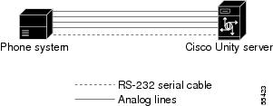
The NEC NEAX 2000 serial MCI integration uses a data link, which consists of an RS-232 serial cable connecting the phone system to the Cisco Unity server. The voice messaging lines from the phone system connect to the analog voice cards in the Cisco Unity server. The following illustration shows the required connections.

Figure 1-1 Connections Between the Phone System and Cisco Unity

The phone system sends the following information through the data link:

The extension of the called party

The reason for the forward (the extension is busy, does not answer, or is set to forward all calls)

The extension of the calling party (for internal calls) or the phone number of the calling party (if it is an external call and the system uses caller ID)

Cisco Unity uses this information to answer the call appropriately. For example, a call forwarded to Cisco Unity is answered with the personal greeting of the subscriber. If the phone system routes the call to Cisco Unity without this information, Cisco Unity answers with the opening greeting.

Integration Features

The NEC NEAX 2000 integration with Cisco Unity provides the following features:

Call forward to personal greeting

When an incoming call is routed to an unanswered or busy extension, the call is forwarded to the voice mail of the subscriber. The caller then hears the personal greeting of the subscriber and can leave a message.

Caller ID

Cisco Unity receives caller ID information from the phone system (if available). This information appears in the subject line of the message in the desktop messaging application.

Easy message access

A subscriber can retrieve messages without entering an ID. Cisco Unity identifies a subscriber based on the extension from which the call originated. A password may be required.

Identified subscriber messaging

Cisco Unity automatically identifies a subscriber who leaves a message during a forwarded internal call, based on the extension from which the call originated.

Message waiting indication

When a message is waiting for a subscriber, Cisco Unity notifies the phone system to activate the message waiting indicator (MWI) on the subscriber's extension (a lamp or a stutter dial tone).


Programming the Phone System

If you use programming options other than those supplied in the following procedure, the performance of the integration may be affected.

If you want to remap extension numbers (for example, when multiple subscribers use a single phone, or when multiple extension numbers on a single phone should go to a single subscriber greeting), see Appendix B, "Remapping Extension Numbers."

You can use a Maintenance Administration Terminal (MAT) or a phone to program the phone system.

To program the phone system


Step 1 If the AP00 cards are installed for the first time, initialize the cards. Otherwise, go to Step 2.

Step 2 Use command 17 to assign all voice messaging system ports to a UCD group.

If the number of voice messaging system ports exceeds the number of supported ports in a UCD group, specify additional UCD groups, and then link them together.

Make sure that the phone system sends calls only to Cisco Unity voice ports in the UCD group that are set to Answer Calls on the System > Ports page in the Cisco Unity Administrator. Calls sent to a voice port not set to Answer Calls cannot be answered by Cisco Unity and may cause other problems.

Step 3 Program each phone to forward calls to the UCD pilot number assigned to the voice messaging ports, based on one of the following Cisco Unity call transfer types.

Table 1-1 Transfer Types for UCD Pilot Number 

Transfer Type
Usage

Release transfer
(blind transfer)

Program the phone to forward calls to the UCD pilot number when:

The extension is busy

The call is not answered

Supervised transfer

Program the phone to forward calls to the UCD pilot number only when the call is not answered. Confirm that call forwarding is disabled when the extension is busy.


Step 4 Use command D001 to set the RS-232 serial data port connected to Cisco Unity as follows:

9600 baud

8 data bits

1 stop bit

No parity

Step 5 Use command D001, subfunction 80, to set the RS-232 serial data port for MCI with a value of 24.

Step 6 Use command 08 command to make the following settings.

Table 1-2 Command 08 Settings 

Feature
Setting

443

0 (VMS with MCI)

025

0 (MSG only)

444

0 (Available)


Step 7 Use command 13 to make the following settings.

Table 1-3 Command 13 Settings 

YY Feature
Setting

03

Set the station number for each subscriber to 0 (To provide).

10

Set each station number for each voice messaging port to 0 (To provide).

22

Set each station number for each voice messaging port to 0 (To provide).


Step 8 Use command 90 to program a key for message retrieval on the phone for each subscriber.

Table 1-4 Command 90 Settings 

YY Feature
Setting

00

Type the extension number, the key on the phone to be programmed, then F1005.


Configuring Cisco Unity for the Integration

After ensuring that the Cisco Unity server is ready for the integration by completing the appropriate tasks in the Cisco Unity Installation Guide, perform the following procedures to confirm that the integration is enabled and to enter the port settings.

To confirm that the integration is enabled


Step 1 On the Cisco Unity server, go to the Cisco Unity Administrator by doing one of the following:

In Internet Explorer, go to http://<server name>/web/sa.

Double-click the desktop shortcut to the Cisco Unity Administrator.

Step 2 Go to System > Licensing > Licensed Features.

Step 3 In the Integration field, confirm that the setting is Serial for a single phone system integration or Multiple Integrations for a dual phone system integration.

Step 4 If the setting is not Serial or Multiple Integrations, contact your sales representative for the necessary system key.

Step 5 Go to System > Switch. Confirm that the settings match those in the following table. If the settings are incorrect, integration features may not be enabled.

Table 1-5 Switch Settings 

Switch Parameter
Required Setting

Manufacturer

NEC

Model

NEAX 2000

Switch PBX Software Version

All w/ analog ports

Integration

Serial


Step 6 Click the Save icon.


To enter port settings


Step 1 In the Cisco Unity Administrator, go to System > Ports.

Step 2 Select a port in the table.

Step 3 Indicate the settings for the port.

For a hunt group, use the first voice-messaging ports for incoming calls and the last ports to dial out. This helps minimize the possibility of a collision, in which an incoming call arrives on a port at the same time that Cisco Unity takes the port off-hook to dial out.

Step 4 Type the extension for the port. If the extension for the port is not entered correctly, the integration will not work.

Step 5 Repeat Steps 2 through 4 for the remaining ports.

Step 6 Click the Save icon.

Step 7 For the settings to take effect, exit and restart the Cisco Unity software. For more information, see Appendix A, "Exiting and Starting the Cisco Unity Software and Server."


Testing the Integration

To test whether Cisco Unity and the phone system are integrated correctly, perform the procedures in the order listed.

If any of the steps indicates a failure, see the following documentation as appropriate:

The installation guide for the phone system

Cisco Unity Troubleshooting Guide

This integration guide

To set up the test configuration


Step 1 Set up two test extensions (Phone 1 and Phone 2) on the same phone system that Cisco Unity is connected to.

Step 2 Set Phone 1 to forward calls to the Cisco Unity pilot number when calls are not answered.

Step 3 In the Cisco Unity Administrator, go to Subscribers > Subscribers > Profile.

If Example Subscriber is not displayed, click the Find icon (the magnifying glass) in the title bar, then click Find, and select Example Subscriber in the list that appears.

Step 4 In the Extension field, enter the extension of Phone 1.

Step 5 Click the Save icon.

Step 6 In the navigation bar, click Call Transfer to go to Subscribers > Subscribers > Call Transfer for Example Subscriber.

For more information on transfer settings, refer to the "Subscriber Template Call Transfer Settings" section in the Help for the Cisco Unity Administrator.

Step 7 Under Transfer Incoming Calls, click Yes, Ring Subscriber's Extension, and confirm that the extension number is for Phone 1.

Step 8 Under Transfer Type, click Release to Switch.

Step 9 Click the Save icon.

Step 10 In the navigation bar, click Messages to go to Subscribers > Subscribers > Messages for Example Subscriber.

Step 11 Under Message Waiting Indicators (MWIs), check Use MWI for Message Notification.

Step 12 In the Extension field, enter x.

Step 13 Click the Save icon.

Step 14 Open the Status Monitor by doing one of the following:

In Internet Explorer, go to http://<server name>/web/sm.

Double-click the desktop shortcut to the Status Monitor.

In the Windows systray, right-click the Cisco Unity icon and click Status Monitor.


To test an external call with release transfer


Step 1 From Phone 2, enter the access code necessary to get an outside line, then enter the number outside callers use to dial directly to Cisco Unity.

Step 2 On the Status Monitor, note the port that handles this call.

Step 3 When you hear the opening greeting, enter the extension for Phone 1. Hearing the opening greeting means that the port is configured correctly.

Step 4 Confirm that Phone 1 rings and that you hear a ringback tone on Phone 2. Hearing a ringback tone means that Cisco Unity released the call and transferred it to Phone 1.

Step 5 Do not answer Phone 1, and confirm that the state of the port handling the call changes to "Idle." This state means that release transfer succeeds.

Step 6 Confirm that, after the number of rings that the phone system is set to wait, the call is forwarded to Cisco Unity and that you hear the greeting for Example Subscriber. Hearing the greeting means that the phone system forwarded the unanswered call and the call-forward information to Cisco Unity, which correctly interpreted the information.

Step 7 On the Status Monitor, note the port that handles this call.

Step 8 Leave a message for Example Subscriber and hang up Phone 2.

Step 9 On the Status Monitor, confirm that the state of the port handling the call changes to "Idle." This state means that the port was successfully released when the call ended.

Step 10 Confirm that the MWI on Phone 1 is activated. The activated MWI means that the phone system and Cisco Unity are successfully integrated for turning on MWIs.


To test an internal call with release transfer


Step 1 From Phone 1, enter the internal pilot number for Cisco Unity.

Step 2 When asked for your password, enter 12345. Hearing the request for your password means that the phone system sent the necessary call information to Cisco Unity, which correctly interpreted the information.

Step 3 Confirm that you hear the recorded voice name for Example Subscriber. Hearing the voice name means that Cisco Unity correctly identified the subscriber by the extension.

Step 4 When asked whether you want to listen to your messages, press 1.

Step 5 After listening to the message, press 3 to delete the message.

Step 6 Confirm that the MWI on Phone 1 is deactivated. The deactivated MWI means that the phone system and Cisco Unity are successfully integrated for turning off MWIs.

Step 7 Hang up Phone 1.

Step 8 On the Status Monitor, confirm that the state of the port handling the call changes to "Idle." This state means that the port was successfully released when the call ended.


To set up supervised transfer on Cisco Unity


Step 1 In the Cisco Unity Administrator, go to Subscribers > Subscribers > Call Transfer.

If Example Subscriber is not displayed, click the Find icon (the magnifying glass) in the title bar, then click Find, and select Example Subscriber in the list that appears.

For more information on transfer settings, refer to the "Subscriber Template Call Transfer Settings" section in the Help for the Cisco Unity Administrator.

Step 2 Under Transfer Type, click Supervise Transfer.

Step 3 Set the Rings to Wait For field to 3.

Step 4 Click the Save icon.


To test supervised transfer


Step 1 From Phone 2, enter the access code necessary to get an outside line, then enter the number outside callers use to dial directly to Cisco Unity.

Step 2 On the Status Monitor, note the port that handles this call.

Step 3 When you hear the opening greeting, enter the extension for Phone 1. Hearing the opening greeting means that the port is configured correctly.

Step 4 Confirm that Phone 1 rings and that you do not hear a ringback tone on Phone 2. Instead, you should hear the indication your phone system uses to mean that the call is on hold (for example, music or beeps).

Step 5 Do not answer Phone 1, and confirm that the state of the port handling the call remains "Busy." This state and hearing an indication that you are on hold mean that Cisco Unity is supervising the transfer.

Step 6 Confirm that, after three rings, you hear the greeting for Example Subscriber. Hearing the greeting means that Cisco Unity successfully recalled the supervised-transfer call.

Step 7 During the greeting, hang up Phone 2.

Step 8 On the Status Monitor, confirm that the state of the port handling the call changes to "Idle." This state means that the port was successfully released when the call ended.


To return Example Subscriber to the default settings


Step 1 In the Cisco Unity Administrator, go to Subscribers > Subscribers > Call Transfer.

If Example Subscriber is not displayed, click the Find icon (the magnifying glass) in the title bar, then click Find, and select Example Subscriber in the list that appears.

Step 2 Under Transfer Incoming Calls, click No (Send Directly to Subscriber's Greeting).

Step 3 In the navigation bar, click Profile to go to Subscribers > Subscribers > Profile.

Step 4 In the Extension field, enter 99990.

Step 5 Click the Save icon.

Step 6 In the navigation bar, click Messages to go to Subscribers > Subscribers > Messages for Example Subscriber.

Step 7 Under Message Waiting Indicators (MWIs), uncheck Use MWI for Message Notification.

Step 8 Click the Save icon.


Integrating a Cisco Unity Failover (Secondary) Server

A Cisco Unity failover server is a secondary (or backup) server that provides voice messaging services if the primary Cisco Unity server becomes inactive. For information on installing a secondary server, refer to the Cisco Unity Installation Guide.

Requirements

The following components are required to integrate a Cisco Unity secondary server:

Phone System

A serial data port for the MCI data link.

A data splitter unit (recommended: B&B Electronics 9-pin modem data splitter, model 9PMDS) to split the single data link into two serial cables.

Two additional RS-232 serial cables (to be used with the serial cable from the integration of the primary server), one connecting the data port in the phone system to the data splitter unit, the second connecting data splitter unit to the serial port on the primary Cisco Unity server, and the third connecting the data splitter unit to the serial port on the secondary Cisco Unity server.

Cisco Unity Server

One secondary Cisco Unity server for each primary server installed and ready for the integration, as described in the Cisco Unity Installation Guide and earlier in this integration guide.

The appropriate cable configuration for each analog voice messaging port to simultaneously connect the phone system to the corresponding ports on both the primary and the secondary servers. For example, connect port 1 on the phone system with both port 1 on the primary server and port 1 on the secondary server.

A system key that enables the integration, the appropriate number of voice messaging ports, and the secondary server.

Integration Description

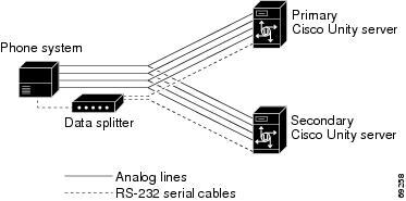
The phone system uses a data link to send call information to the Cisco Unity servers. The data splitter unit splits the single serial cable into two serial cables, enabling the data link to connect to the two Cisco Unity servers. The analog voice messaging lines from the phone system provide voice connectivity to the Cisco Unity servers. Figure 1-2 shows the required connections.

Figure 1-2 Connections Between the Phone System and Cisco Unity Servers

The primary and secondary servers act in the following manner:

When the primary server is operating normally, the secondary server is inactive.

When the primary server becomes inactive, the secondary server becomes active.

When the primary server becomes active again, the secondary server becomes inactive.

Setting Up the Failover (Secondary) Server

Do the following procedure to integrate the Cisco Unity secondary server.

To set up the failover (secondary) server


Step 1 Install a secondary server with the same configuration as the primary server. For installation instructions, refer to the Cisco Unity Installation Guide.

Step 2 Make all voice connections from the phone system to the corresponding ports on both the primary server and the secondary server. For example, connect port 1 from the phone system with port 1 on both the primary and the secondary servers.

Step 3 Connect one serial cable from the serial port on the phone system to the data splitter unit.

Step 4 Connect the remaining two serial cables from two serial ports on the data splitter unit to the serial ports on the Cisco Unity servers, one serial cable to the primary server, and the other serial cable to the secondary server.

Step 5 In the Cisco Unity Administrator of the secondary server, enter the settings on the System > Ports page to match the port settings on the primary server.


No changes to the hunt group programming on the phone system are necessary.