Avaya Definity Gx/PBXLink Integration Guide for Cisco Unity 3.0
Avaya Definity Gx/PBXLink Integration

Table Of Contents

Avaya Definity Gx/PBXLink Integration

Integration Overview

Integration Steps

Requirements

Integration Description

Integration Features

Configuring Cisco Unity for the Integration

Programming the Phone System

Setting up the PBXLink Box

Testing the Integration


Avaya Definity Gx/PBXLink Integration


Integration Overview

Before performing the following integration steps, confirm that the Cisco Unity server is ready for the integration by completing the appropriate tasks in Chapters 1 through 3 of the Cisco Unity Installation Guide.

Integration Steps

Follow these steps to set up this integration.

1. Review the system and equipment requirements to confirm that all phone system and Cisco Unity server requirements have been met. See the "Requirements" section.

2. Configure Cisco Unity for the integration. See the "Configuring Cisco Unity for the Integration" section.

3. Program the phone system and extensions. See the "Programming the Phone System" section.

4. Install and configure the Connected Systems PBXLink box. See the "Setting up the PBXLink Box" section.

5. Test the integration. See the "Testing the Integration" section.

Requirements

The Avaya Definity/PBXLink integration supports configurations of the following components:

Phone System

An Avaya Definity phone system with one or two digital lines connected to the PBX ports on the PBXLink box. The line or lines must be compatible with the 7434D or 8434D digital phones.

For each voice messaging port, one analog port connected to the voice cards in the Cisco Unity server.

The SMDI port in the PBXLink box connected to a serial port (COM1 is the default) on the Cisco Unity server with an RS-232 serial cable. If multiple PBXLink boxes are installed, the SMDI port of the last PBXLink box is connected to the Management port of the first PBXLink box with an RS-232 serial cable. The SMDI port of the first PBXLink box is connected to a serial port (COM1 is the default) on the Cisco Unity server with another RS-232 serial cable. Make sure that the serial protocol parameters for the Management port of the first PBXLink box are set to the same values as the SMDI port.

The phone system ready for the integration as described in the installation guide for the phone system.

Cisco Unity Server

The Dialogic® D/41EPCI, D/120JCT-LS, or D/120JCT-Euro voice cards, installed.

Cisco Unity installed and ready for the integration, as described in the Cisco Unity Installation Guide.


Caution To prevent Windows from mistaking the serial connection for a serial mouse when rebooting the Cisco Unity server, confirm that the Boot.ini file is set according to instructions. Otherwise, the integration will not work properly. For details on setting up the Boot.ini file, refer to "Installing Windows 2000 Server" in Chapter 3 of the Cisco Unity Installation Guide.

A system key that enables the integration and the appropriate number of voice messaging ports.

An available serial port (COM1 is the default).

Integration Description

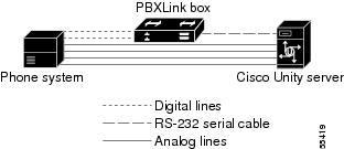
The Avaya Definity/PBXLink integration uses one or more PBXLink boxes, with each box emulating up to two Avaya 7434D or 8434D digital phones. The PBXLink is connected to the phone system with digital phone lines and connected to the Cisco Unity server with an RS-232 serial cable. The voice messaging lines from the phone system connect to the analog voice cards in the Cisco Unity server.

This integration requires that bridged mode be used.

The PBXLink box receives the following call information from the phone system:

The extension of the called party

The reason for the forward (the extension is busy, does not answer, or is set to forward all calls)

The extension of the calling party (for internal calls) or the phone number of the calling party (if it is an external call and the system uses caller ID)

The PBXLink box formats this information as a Simplified Message Desk Interface (SMDI) packet and sends the packet to Cisco Unity through the RS-232 serial cable.

Cisco Unity uses this information to answer the call appropriately. For example, a call forwarded to Cisco Unity is answered with the personal greeting of the subscriber. If the phone system routes the call to Cisco Unity without this information, Cisco Unity answers with the opening greeting.

Cisco Unity also activates or deactivates message waiting indicators.

For additional information, refer to Chapter 1 in the PBXLink User Guide, which is available at the following website:

http://www.connectedsystems.com/pbx/48/pbxlink48.html

Configuration for 24 or Fewer Ports

Avaya integrations with 24 or fewer ports can use one of three configurations:

A single PBXLink-24 box with Port A set for both calls and MWIs.

Two PBXLink-24 boxes with Port A of one box set for MWIs only and Port A of the second box set for calls only.

A single PBXLink-48 box with Port A set for MWIs only and Port B set for calls only.

Configuration for 25 to 48 Ports

Avaya integrations with 25 to 48 ports can use one of two configurations:

Two PBXLink-24 boxes with Port A of one box set for both calls and MWIs and Port A of the second box set for calls only.

A single PBXLink-48 box with Port A set for MWIs only and Port B set for calls only, and a single PBXLink-24 box with Port A set for calls only.

It is not possible to use a single PBXLink-48 box with Port A set to both calls and MWIs and Port B set for calls only. In this configuration, Port B is disabled.

PBXLink Box Connections

A single PBXLink box is connected to the phone system with a digital phone line and connected to the Cisco Unity server with an RS-232 serial cable. The voice messaging lines from the phone system connect to the analog voice cards in the Cisco Unity server. The following illustration shows the required connections.

Figure 1-1 Serial Connection Between a Single PBXLink Box and Cisco Unity

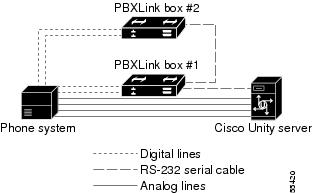
Multiple PBXLink boxes are connected to the Cisco Unity server by using an RS-232 cable to connect the SMDI port from the last PBXLink box to the Management port of the first PBXLink box. Another RS-232 cable is then used to connect the SMDI port of the first PBXLink box to the Cisco Unity server. The voice messaging lines from the phone system connect to the analog voice cards in the Cisco Unity server. The following illustration shows the required connections.

Figure 1-2 Serial Connections Between Multiple PBXLink Boxes and Cisco Unity

Integration Features

The Avaya Definity/PBXLink integration with Cisco Unity provides the following features:

Call forward to personal greeting

When an incoming call is routed to an unanswered or busy extension, the call is forwarded to the voice mail of the subscriber. The caller then hears the personal greeting of the subscriber and can leave a message.

Caller ID

Cisco Unity receives caller ID information from the phone system (if available). This information appears in the subject line of the message in the desktop messaging application.

Easy message access

A subscriber can retrieve messages without entering an ID. Cisco Unity identifies a subscriber based on the extension from which the call originated. A password may be required.

Identified subscriber messaging

Cisco Unity automatically identifies a subscriber who leaves a message during a forwarded internal call, based on the extension from which the call originated.

Message waiting indication

When a message is waiting for a subscriber, Cisco Unity notifies the phone system to activate the message waiting indicator (MWI) on the subscriber's extension (a lamp or a stutter dial tone).


Configuring Cisco Unity for the Integration

After ensuring that the Cisco Unity server is ready for the integration by completing the appropriate tasks in Chapters 1 through 3 of the Cisco Unity Installation Guide, perform the following procedures to confirm that the integration is enabled and to enter the port settings.

To confirm that the integration is enabled


Step 1 On the Cisco Unity server, go to the Cisco Unity Administrator by doing one of the following:

In Internet Explorer, go to http://<server name>/web/sa.

Double-click the desktop shortcut to the Cisco Unity Administrator.

Step 2 Go to System > Licensing > Licensed Features.

Step 3 In the Integration field, confirm that the setting is Serial for a single phone system integration or Multiple Integrations for a dual phone system integration.

Step 4 If the setting is not Serial or Multiple Integrations, contact your sales representative for the necessary system key.

Step 5 Go to System > Switch. Confirm that the settings match those in the following table. If the settings are incorrect, integration features may not be enabled.

Table 1-1 Switch Settings

Switch Parameter
Required Setting

Manufacturer

Avaya

Model

Definity Gx

Switch PBX Software Version

All

All (analog MWI)

Integration

Serial


Step 6 If you selected All (Analog MWI) in the Switch PBX Software Version field, edit the codes that turn message waiting indication on and off, as necessary. The MWI codes are located in the Active Switch Setting area at the top of the Switch Settings page.

Step 7 Click the Save icon.


To enter port settings


Step 1 Go to System > Ports.

Step 2 Select a port in the table.

Step 3 Indicate the settings for the port.

Step 4 Type the extension for the port.

Step 5 Repeat Steps 2 through 4 for the remaining ports.

Step 6 Click the Save icon.

Step 7 For the settings to take effect, exit and restart the Cisco Unity software. For more information, see Appendix A, "Exiting and Starting the Cisco Unity Software and Server."


Programming the Phone System

If you use programming options other than those supplied in the following procedures, the performance of the integration may be affected.

If you want to remap extension numbers (for example, when multiple subscribers use a single phone, or when multiple extension numbers on a single phone should go to a single subscriber greeting), see Appendix B, "Remapping Extension Numbers."

Make sure that the phone system sends calls only to Cisco Unity voice ports that are set to Answer Calls on the System > Ports page in the Cisco Unity Administrator. Calls sent to a voice port not set to Answer Calls cannot be answered by Cisco Unity. And, if certain voice cards are installed, the call will not be dropped, but the port remains unavailable for use until the Cisco Unity server is restarted.

To program the phone system


Step 1 Use the Add Station <extension number> command (for example, Add Station 2001) to assign an extension number for each voice messaging port. Set the following options and press Enter.

The options available may vary depending on the software version of your phone system.

Table 1-2 Voice Messaging Port Options

Option
Setting

Extension

<the extension number of the voice messaging port>

Type

2500

Port

<the physical address of the port>

Lock Messages?

n

Test?

n

Name

VoiceMail 2001

(The extension number must appear within the first 16 characters.)

LWC Reception?

n

LWC Activation?

y

Redirect Notification?

n

Off Premise Station?

n

Coverage Msg Retrieval Permission?

n

Data Restriction?

y

Call Waiting Indication?

n

Distinctive Audible Alert?

n

Message Waiting Indicator?

n

Adjunct Supervision

y


Step 2 Use the Add Station <extension number> command (for example, Add Station 2999) to assign an extension number for each digital line to the PBXLink box. Set the digital line options (Table 1-3), button assignments (Table 1-4), and the appropriate feature button assignments (either Table 1-5, or both Table 1-6 and Table 1-7), then press Enter.

Table 1-3 Digital Line Options for All Lines

Option
Setting

Extension

<the extension number of the digital line>

Type

8434D

7434D

Port

<the physical address of the port>

Data Module?

n

Expansion Module?

n

LWC Reception

None

LWC Activation?

y

CDR Privacy?

n

Redirect Notification?

n

Per Button Ring Control?

n

Bridged Call Alerting?

n

Active Station Ringing

Single

Auto Select Any Idle Appearance?

n

Coverage Msg Retrieval?

y

Auto Answer

None

Data Restriction?

n

Idle Appearance Preference?

n

Restrict Last Appearance?

y

Audible Message Waiting?

n

Display Client Redirection?

n

Select Last Used Appearance?

n


Table 1-4 Button Assignments for All Lines

Button Assignment
Setting

1

call-appr

2

call-appr

3

call-appr

4

normal

(Use the Normal setting for programming a 7434D phone. Leave the setting blank for an 8434D phone.)

5

inspect

6


7


8


9


10

call-appr


Table 1-5 Feature Button Assignments for Line Without Load Balancing

Feature Button Number
Setting

1

abrdg-appr Extn: <1st voice mail extension>

2

abrdg-appr Extn: <2nd voice mail extension>

3

abrdg-appr Extn: <3rd voice mail extension>

.
.
.

<the remaining voice mail extensions>


Table 1-6 Feature Button Assignments for First Line with Load Balancing

Feature Button Number
Setting

1

abrdg-appr Extn: <1st voice mail extension>

2

abrdg-appr Extn: <3rd voice mail extension>

3

abrdg-appr Extn: <5th voice mail extension>

.
.
.

<the remaining odd-numbered voice mail extensions>


Table 1-7 Feature Button Assignments for Second Line with Load Balancing

Feature Button Number
Setting

1

abrdg-appr Extn: <2nd voice mail extension>

2

abrdg-appr Extn: <4th voice mail extension>

3

abrdg-appr Extn: <6th voice mail extension>

.
.
.

<the remaining even-numbered voice mail extensions>


If the phone system has 1 to 8 voice messaging ports or if it does not have vectoring capability, perform the procedure "To set up hunt groups for one to eight voice messaging ports or for phone systems without vectoring capability." Otherwise, perform the procedure "To set up hunt groups for more than eight voice messaging ports."

To set up hunt groups for one to eight voice messaging ports or for phone systems without vectoring capability


Refer to Chapter 6 in the PBXLink User Guide, which is available at the following website:

http://www.connectedsystems.com/pbx/48/pbxlink48.html


To set up hunt groups for more than eight voice messaging ports


Step 1 For a phone system with more than eight voice messaging ports, use the Add Vdn <extension number> command (for example Add Vdn 2000) to set up a vector directory number for the pilot number (extension 2000 in this example). Set the following options and press Enter.

Table 1-8 Vector Direction Number Options

Option
Setting

Extension

<the pilot number>

Name

VoiceMail 2000

Display Override?

n

COR

1

Vector Number

1

(must match the Number option in Table 1-9)

Measured

none


Step 2 Use the Add Vector 1 or the Change Vector 1 command to define the vector. Set the options according to the following example of a six-line system and a single PBXLink digital port. Then press Enter.

Table 1-9 Vector Definition Options for a Single Digital Port

Option
Setting

Number

1

(must match the Vector Number option in Table 1-8)

Name

voicevec

ASAI Routing?

n

Basic?

y

Prompting?

n

01

wait time 0 secs hearing ringback

02

route to number 2001 if unconditionally

(use the first voice messaging port extension)

03

route to number 2002 if unconditionally

04

route to number 2003 if unconditionally

05

route to number 2004 if unconditionally

06

route to number 2005 if unconditionally

07

route to number 2006 if unconditionally

08

busy


For a system with two PBXLink digital ports, use the following example, which bridges every second extension to Port A and the remaining extensions to Port B.

Table 1-10 Vector Definition Options for Call Vector 1

Option
Setting

Number

1

Name

voicevec1

ASAI Routing?

n

Basic?

y

Prompting?

n

01

wait time 0 secs hearing ringback

02

route to number 2001 if unconditionally

03

route to number 2002 if unconditionally

04

route to number 2003 if unconditionally

05

route to number 2004 if unconditionally

06

route to number 2005 if unconditionally

07

route to number 2006 if unconditionally

08

route to number 2007 if unconditionally

09

route to number 2008 if unconditionally

10

route to number 2009 if unconditionally

11

route to number 2010 if unconditionally

12

goto vector 2 if unconditionally


Table 1-11 Vector Definition Options for Call Vector 2

Option
Setting

Number

2

Name

voicevec2

ASAI Routing?

n

Basic?

y

Prompting?

n

01

route to number 2011 if unconditionally

02

route to number 2012 if unconditionally

03

route to number 2013 if unconditionally

04

route to number 2014 if unconditionally

05

route to number 2015 if unconditionally

06

route to number 2016 if unconditionally

07

route to number 2017 if unconditionally

08

route to number 2018 if unconditionally

09

route to number 2019 if unconditionally

10

route to number 2020 if unconditionally

11

busy


After programming the phone system, it is necessary to set up the direct lines for users on the phone system.

To set up user phones


Step 1 Use the Change Station (extension number) command to display the Station screen for each extension.

Step 2 In the Name field, enter the user's name and extension. The PBXLink box can display only the first 16 characters, and the extension must appear in these 16 characters.

Step 3 In the Coverage Path field, enter 1.


Setting up the PBXLink Box

To set up the PBXLink box, you can access the configuration menus through the display panel and buttons on top of the PBXLink box. For details, refer to the PBXLink User Guide, which is available at the following website:

http://www.connectedsystems.com/pbx/48/pbxlink48.html

To set up the PBXLink box


Step 1 Select Configuration and press Enter.

Step 2 Select Integration and confirm that Stopped is selected.

Step 3 Select PBX Type, and select either Lucent 2 wire or Lucent 4 wire. If the setting you select is not the same as the setting that first appeared, the PBXLink box restarts.

Step 4 If the PBXLink box restarts, repeat Step 1, then skip to Step 5. Otherwise, continue with Step 5.

Step 5 Select PBX Options and press Enter. The list of phone systems appears.

Step 6 Select Phone Set, enter either 8434D or 7434D, as you set up the digital port with the Add Station command.

Step 7 Select Voice Coding, select Mu Law for North America. Otherwise, select A Law.

Step 8 Select Analog Ports on A, and enter the number of voice messaging ports that Port A monitors, then press Enter.

Step 9 If you are setting up a PBXLink-48 box, select Analog Ports on B, and enter the number of voice messaging ports that Port B monitors, then press Enter. Otherwise, skip to the next step.

Step 10 Select Configure Port A, select one of the following settings for Port A, then press Enter.

Table 1-12 Port Configuration Settings

Setting
Meaning

Calls Only

The port handles only calls.

MWI Only

The port handles only MWIs.

Calls + MWI

The port handles both calls and MWIs.


Step 11 If you are setting up a PBXLink-48 box, select Configure Port B, select one of the preceding settings for Port B, then press Enter. Otherwise, skip to the next step.

Step 12 Select Prime Number, enter the pilot number that the phone system uses to call Cisco Unity, and then press Enter.

Step 13 In the Message Waiting Ind section, confirm that Msg Wait On and Msg Wait Off have the same settings that the phone system was programmed for.

Step 14 Select Extension Length and enter the number of digits in the subscriber extensions. If the subscriber extensions have different lengths, enter the number of digits in the longest extension.

Step 15 Select Integration, select Started, and press Enter.


If the system has two or more, digital PBXLink lines, it is recommended that you balance the load among the PBXLink boxes by setting up the Port LTNs for random operation.

To set up the port LTNs


Step 1 Select Configuration and press Enter. Then select SMDI Options and press Enter.

Step 2 Select Port A LTNs (or the port that handles calls), then select Random and press Enter.

Step 3 Select Setup Random LTNs, enter the voice messaging port values (not the extension) as shown in the following table, then press Enter.

Table 1-13 Random LTN Settings for Odd-Numbered Ports

LTN Number
Voice Messaging Port Value

0

0001

1

0003

2

0005

.
.
.

<the remaining odd-numbered voice messaging ports>


Step 4 Repeat Steps 1 through 3 on the interface of the next PBXLink box.

Step 5 Select Setup Random LTNs, enter the voice messaging port values (not the extension) as shown in the following table, then press Enter.

Table 1-14 Random LTN Settings for Even-Numbered Ports

LTN Number
Voice Messaging Port Value

0

0002

1

0004

2

0006

.
.
.

<the remaining even-numbered voice messaging ports>


Step 6 Select Integration, select Started, and press Enter.


Testing the Integration

To test whether Cisco Unity and the phone system are integrated correctly, perform the procedures in the order listed.

If any of the steps indicates a failure, see the following documentation as appropriate:

The installation guide for the phone system

Cisco Unity Troubleshooting Guide

This integration guide

To set up the test configuration


Step 1 Set up two test extensions (Phone 1 and Phone 2) on the same phone system that Cisco Unity is connected to.

Step 2 Set Phone 1 to forward calls to the Cisco Unity pilot number when calls are not answered.

Step 3 In the Cisco Unity Administrator, go to Subscribers > Subscribers > Profile.

If Example Subscriber is not displayed, click the Find icon (the magnifying glass) in the title bar, then click Find, and select Example Subscriber in the list that appears.

Step 4 In the Extension field, enter the extension of Phone 1.

Step 5 Click the Save icon.

Step 6 In the navigation bar, click Call Transfer to go to Subscribers > Subscribers > Call Transfer for Example Subscriber.

For more information on transfer settings, refer to the "Subscriber Template Call Transfer Settings" section in the Help for the Cisco Unity Administrator.

Step 7 Under Transfer Incoming Calls, click Yes, Ring Subscriber's Extension, and confirm that the extension number is for Phone 1.

Step 8 Under Transfer Type, click Release to Switch.

Step 9 Click the Save icon.

Step 10 In the navigation bar, click Messages to go to Subscribers > Subscribers > Messages for Example Subscriber.

Step 11 Under Message Waiting Indicators (MWIs), check Use MWI for Message Notification.

Step 12 In the Extension field, enter x.

Step 13 Click the Save icon.

Step 14 Open the Status Monitor by doing one of the following:

In Internet Explorer, go to http://<server name>/web/sm.

Double-click the desktop shortcut to the Status Monitor.

In the Windows systray, right-click the Cisco Unity icon and click Status Monitor.


To test an external call with release transfer


Step 1 From Phone 2, enter the access code necessary to get an outside line, then enter the number outside callers use to dial directly to Cisco Unity.

Step 2 On the Status Monitor, note the port that handles this call.

Step 3 When you hear the opening greeting, enter the extension for Phone 1. Hearing the opening greeting means that the port is configured correctly.

Step 4 Confirm that Phone 1 rings and that you hear a ringback tone on Phone 2. Hearing a ringback tone means that Cisco Unity released the call and transferred it to Phone 1.

Step 5 Do not answer Phone 1, and confirm that the state of the port handling the call changes to "Idle." This state means that release transfer succeeds.

Step 6 Confirm that, after the number of rings that the phone system is set to wait, the call is forwarded to Cisco Unity and that you hear the greeting for Example Subscriber. Hearing the greeting means that the phone system forwarded the unanswered call and the call-forward information to Cisco Unity, which correctly interpreted the information.

Step 7 On the Status Monitor, note the port that handles this call.

Step 8 Leave a message for Example Subscriber and hang up Phone 2.

Step 9 On the Status Monitor, confirm that the state of the port handling the call changes to "Idle." This state means that the port was successfully released when the call ended.

Step 10 Confirm that the MWI on Phone 1 is activated. The activated MWI means that the phone system and Cisco Unity are successfully integrated for turning on MWIs.


To test an internal call with release transfer


Step 1 From Phone 1, enter the internal pilot number for Cisco Unity.

Step 2 When asked for your password, enter 12345. Hearing the request for your password means that the phone system sent the necessary call information to Cisco Unity, which correctly interpreted the information.

Step 3 Confirm that you hear the recorded voice name for Example Subscriber. Hearing the voice name means that Cisco Unity correctly identified the subscriber by the extension.

Step 4 When asked whether you want to listen to your messages, press 1.

Step 5 After listening to the message, press 3 to delete the message.

Step 6 Confirm that the MWI on Phone 1 is deactivated. The deactivated MWI means that the phone system and Cisco Unity are successfully integrated for turning off MWIs.

Step 7 Hang up Phone 1.

Step 8 On the Status Monitor, confirm that the state of the port handling the call changes to "Idle." This state means that the port was successfully released when the call ended.


To set up supervised transfer on Cisco Unity


Step 1 In the Cisco Unity Administrator, go to Subscribers > Subscribers > Call Transfer.

If Example Subscriber is not displayed, click the Find icon (the magnifying glass) in the title bar, then click Find, and select Example Subscriber in the list that appears.

For more information on transfer settings, refer to the "Subscriber Template Call Transfer Settings" section in the Help for the Cisco Unity Administrator.

Step 2 Under Transfer Type, click Supervise Transfer.

Step 3 Set the Rings to Wait For field to 3.

Step 4 Click the Save icon.


To test supervised transfer


Step 1 From Phone 2, enter the access code necessary to get an outside line, then enter the number outside callers use to dial directly to Cisco Unity.

Step 2 On the Status Monitor, note the port that handles this call.

Step 3 When you hear the opening greeting, enter the extension for Phone 1. Hearing the opening greeting means that the port is configured correctly.

Step 4 Confirm that Phone 1 rings and that you do not hear a ringback tone on Phone 2. Instead, you should hear the indication your phone system uses to mean that the call is on hold (for example, music or beeps).

Step 5 Do not answer Phone 1, and confirm that the state of the port handling the call remains "Busy." This state and hearing an indication that you are on hold mean that Cisco Unity is supervising the transfer.

Step 6 Confirm that, after three rings, you hear the greeting for Example Subscriber. Hearing the greeting means that Cisco Unity successfully recalled the supervised-transfer call.

Step 7 During the greeting, hang up Phone 2.

Step 8 On the Status Monitor, confirm that the state of the port handling the call changes to "Idle." This state means that the port was successfully released when the call ended.


To return Example Subscriber to the default settings


Step 1 In the Cisco Unity Administrator, go to Subscribers > Subscribers > Call Transfer.

If Example Subscriber is not displayed, click the Find icon (the magnifying glass) in the title bar, then click Find, and select Example Subscriber in the list that appears.

Step 2 Under Transfer Incoming Calls, click No (Send Directly to Subscriber's Greeting).

Step 3 In the navigation bar, click Profile to go to Subscribers > Subscribers > Profile.

Step 4 In the Extension field, enter 99990.

Step 5 Click the Save icon.

Step 6 In the navigation bar, click Messages to go to Subscribers > Subscribers > Messages for Example Subscriber.

Step 7 Under Message Waiting Indicators (MWIs), uncheck Use MWI for Message Notification.

Step 8 Click the Save icon.