Feedback
Contents
- Cisco Unified IP Phone
- Cisco Unified IP Phone 8961, 9951, and 9971
- Cisco Unified IP Phone 8961
- Phone Connections for Cisco Unified IP Phone 8961
- Buttons and Hardware
- Cisco Unified IP Phone 9951
- Phone Connections for Cisco Unified IP Phone 9951
- Buttons and Hardware
- Cisco Unified IP Phone 9971
- Phone Connections for Cisco Unified IP Phone 9971
- Buttons and Hardware
- Connect Footstand
- Phone and Cable Lock
- Network Protocols
- Cisco Unified IP Phone 8961, 9951, and 9971 Supported Features
- Feature Overview
- Telephony Feature Administration
- Cisco Unified IP Phone Network Parameters
- Information for End Users
- Cisco Unified IP Phone security features
- Supported security features
- Security Profiles
- Secure Phone Calls
- Secure Conference Call Identification
- Secure Phone Call Identification
- Call Security Interactions and Restrictions
- 802.1X Authentication
- Overview
- Required Network Components
- Best Practices
- Security Restrictions
- Cisco Unified IP Phone Deployment
- Cisco Unified IP Phone Setup in Cisco Unified Communications Manager
- Set up Cisco Unified IP Phone 8961, 9951, and 9971 in Cisco Unified Communications Manager
- Cisco Unified IP Phone Installation
- Set up Cisco Unified IP Phone 8961, 9951, and 9971
- Terminology Differences
Cisco Unified IP Phone
The Cisco Unified IP Phone 8961, 9951, and 9971 provides voice communication over an Internet Protocol (IP) network. The Cisco Unified IP Phone functions much like a digital business phone, allowing you to place and receive phone calls and to access features such as mute, hold, transfer, speed dial, call forward, and more. In addition, because the phone connects to your data network, it offers enhanced IP telephony features, including access to network information and services, and customizeable features and services.
The Cisco Unified IP Phones have the following features:
- 24-bit color phone screen (Cisco Unified IP Phone 9971 has touchscreen support)
- Programmable feature buttons that support up to 5 lines (6 lines for the Cisco Unified IP Phone 9971) or that can be programmed for other features
- Full video capabilities (Cisco Unified IP Phones 9951 and 9971 only)
- Gigabit ethernet connectivity
- Support for an external microphone and speakers
- Bluetooth support for wireless headsets (Cisco Unified IP Phones 9951 and 9971 only)
- Network connectivity by Wi-Fi (Cisco Unified IP Phone 9971 only)
- USB ports:
A Cisco Unified IP Phone, like other network devices, must be configured and managed. These phones encode G.711 a-law, G.711 mu-law, G.722, G.729a, G.729ab, iLBC, and iSAC codecs, and decode G.711 a-law, G.711 mu-law, G.722, G.729, G.729a, G.729b, G.729ab, iLBC, and iSAC codecs.
CautionUsing a cell, mobile, or GSM phone, or two-way radio in close proximity to a Cisco Unified IP Phone might cause interference. For more information, see the manufacturer’s documentation of the interfering device.
- Cisco Unified IP Phone 8961, 9951, and 9971
- Network Protocols
- Cisco Unified IP Phone 8961, 9951, and 9971 Supported Features
- Cisco Unified IP Phone security features
- Cisco Unified IP Phone Deployment
- Terminology Differences
Cisco Unified IP Phone 8961, 9951, and 9971
This section describes the Cisco Unified IP Phone 8961, 9951, and 9971 components. For more information, see Cisco Unified IP Phone 8961, 9951, and 9971 User Guide for Cisco Unified Communications Manager.
- Cisco Unified IP Phone 8961
- Cisco Unified IP Phone 9951
- Cisco Unified IP Phone 9971
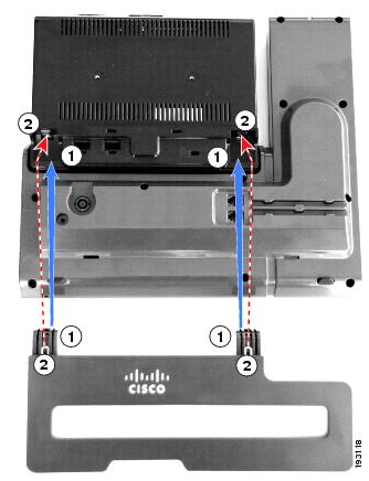
- Connect Footstand
- Phone and Cable Lock
Cisco Unified IP Phone 8961
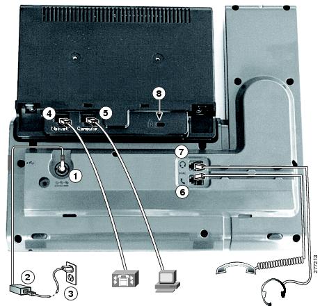
Phone Connections for Cisco Unified IP Phone 8961
Connect your phone to the corporate IP telephony network, using the following diagram.
1
DC adapter port (DC48V)
5
Computer port (10/100/1000 PC) connection
2
AC-to-DC power supply (optional)
6
Handset connection
3
AC power wall plug (optional)
7
Analog headset connection (headset optional)
4
Network port (10/100/1000 SW) with IEEE 802.3af and 802.3at power enabled
8
Anti-theft security lock connector (lock optional)
The following diagram shows the phone from the side.
1
USB port
2
Accessory connector; for example, to connect a Cisco Unified IP Color Key Expansion Module
NoteEach USB port supports the connection of up to five supported and nonsupported devices. Each device connected to the phone is included in the maximum device count. For example, the USB port on your phone can support a maximum of five USB devices (such as three Cisco Unified IP Color Key Expansion modules, one hub, and one other standard USB device). Many third-party USB products count as multiple USB devices, for example, a device containing USB hub and headset can count as two USB devices. For more information, see the USB device documentation.
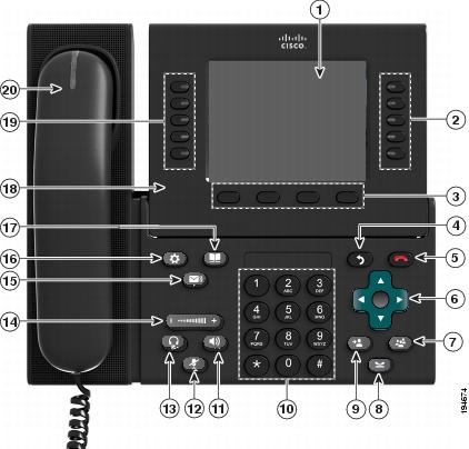
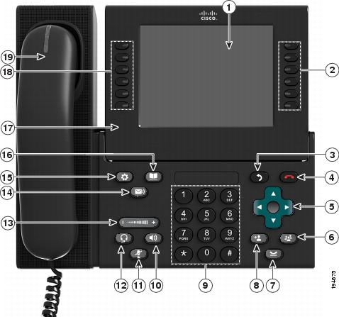
Buttons and Hardware
Your phone provides quick access to your phone lines, features, and call sessions:
- Programmable feature buttons (left side): Use to view calls on a line or access features such as Speed Dial or All Calls. (These buttons are also called feature buttons.)
- Session buttons (right side): Use to perform tasks such as answering a call, resuming a held call, or (when not being used for an active call) initiating phone functions such as displaying missed calls. Each call on your phone is associated with a session button.
Cisco Unified IP Phone 9951
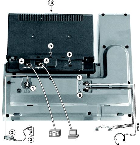
Phone Connections for Cisco Unified IP Phone 9951
Connect your phone to the corporate IP telephony network, using the following diagram.
1
DC adapter port (DC48V)
6
Handset connection
2
AC-to-DC power supply (optional for the network port connection but required for a wifi connection)
7
Analog headset connection (headset optional)
3
AC power wall plug (optional)
8
USB port
4
Network port (10/100/1000 SW) with IEEE 802.3af and 802.3at power enabled
9
Anti-theft security connector (lock optional)
5
Computer port (10/100/1000 PC) connection
10
Camera pin holes (for Cisco Unified Video Camera)
The following picture shows the side of the phone.
1
USB port
3
Speaker port for output to optional external speakers
2
Accessory connector; for example, for connecting a Cisco Unified IP Phone Expansion Module
4
Microphone port for input from optional external microphone
NoteEach USB port supports a maximum of five supported and nonsupported devices that are connected to the phone. Each device connected to the phone is included in the maximum device count. For example, your phone can support five USB devices such as three Cisco Unified IP Color Key Expansion modules, one hub, and one other standard USB device on the side port and five additional standard USB devices on the back port. Many third-party USB products count as multiple USB devices, for example, a device containing USB hub and headset can count as two USB devices. For more information, see the USB device documentation.
Buttons and Hardware
Your phone provides quick access to your phone lines, features, and call sessions:
- Programmable feature buttons (left side): Use to view calls on a line or access features such as Speed Dial or All Calls. These buttons are also called feature buttons.
- Session buttons (right side): Use to perform tasks such as answering a call, resuming a held call, or (when not being used for an active call) initiating phone functions such as displaying missed calls. Each call on your phone is associated with a session button.
Cisco Unified IP Phone 9971
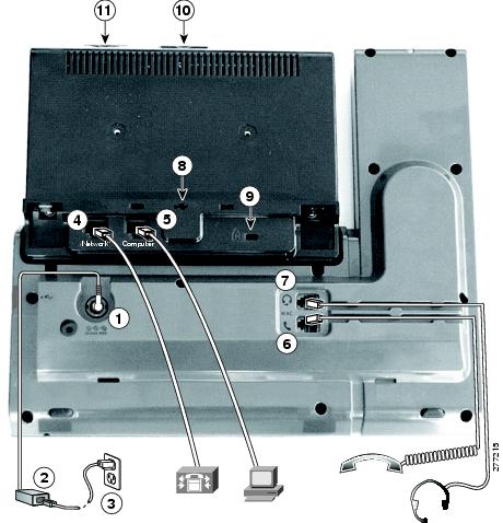
Phone Connections for Cisco Unified IP Phone 9971
Connect your phone to the corporate IP telephony network, using the following diagram.
1
DC adapter port (DC48V)
7
Analog headset connection (optional)
2
AC-to-DC power supply (optional for the network port connection but required for a Wi-Fi connection)
8
USB port
3
AC power wall plug (optional)
9
Anti-theft security lock connector (lock optional)
4
Network port (10/100/1000 SW) with IEEE 802.3af and 802.3at power enabled
10
Camera pin holes (for Cisco Unified Video Camera)
5
Computer port (10/100/1000 PC) connection
11
Secure Digital I/O (SDIO) slot (not used for this release)
6
Handset connection
The following picture shows the side of the phone.
1
USB port
3
Speaker port for output to optional external speakers
2
Accessory connector; for example, for connecting a Cisco Unified IP Phone Expansion Module
4
Microphone port for input from optional external microphone
NoteEach USB port supports the connection of up to five supported and nonsupported devices. Each device connected to the phone is included in the maximum device count. For example, your phone can support five USB devices (such as three Cisco Unified IP Color Key Expansion modules, one hub, and one other standard USB device) on the side port and five additional standard USB devices on the back port. Many third-party USB products count as multiple USB devices, for example, a device containing USB hub and headset can count as two USB devices. For more information, see the USB device documentation.
Buttons and Hardware
Your phone provides quick access to your phone lines, features, and call sessions:
- Use the feature buttons (on the left) to view calls on a line or access features such as Speed Dial or All Calls.
- Use the call session buttons (on the right) to perform tasks such as making a call, answering a call, or resuming a held call. Each call on your phone is associated with a session button.
Phone and Cable Lock
You can secure the Cisco Unified IP Phone 8961, 9951, and 9971 to a desktop by using a laptop cable lock. The lock connects to the antitheft security connector on the back of the phone and the cable can be secured to a desktop.
The security slot can accommodate a lock up to 20 mm wide. Compatible laptop cable locks include the Kensington laptop cable lock and laptop cable locks from other manufacturers that can fit into the security slot on the back of the phone.
Network Protocols
Cisco Unified IP Phones support several industry-standard and Cisco network protocols required for voice communication. The following table provides an overview of the network protocols that the Cisco Unified IP Phone 8961, 9951, and 9971 support.
Table 1 Supported network protocols on the Cisco Unified IP Phone Network protocol
Purpose
Usage notes
Bluetooth
Bluetooth is a wireless personal area network (WPAN) protocol that specifies how devices communicate over short distances.
Cisco Unified IP Phones 9951 and 9971 support Bluetooth 2.1.
Bootstrap Protocol (BootP)
BootP enables a network device, such as the Cisco Unified IP Phone, to discover certain startup information, such as the IP address.
—
Cisco Audio Session Tunnel (CAST)
The CAST protocol allows Cisco Unified IP Phones and associated applications to discover and communicate with the remote IP Phones without requiring changes to the traditional signaling components, such as Cisco Unified Communications Manager (CM) and gateways.
The Cisco Unified IP Phone uses CAST as an interface between CUVA and Cisco Unified Communications Manager using the Cisco Unified IP Phone as a SIP proxy.
Cisco Discovery Protocol (CDP)
CDP is a device-discovery protocol that runs on all Cisco-manufactured equipment.
Using CDP, a device can advertise its existence to other devices and receive information about other devices in the network.
The Cisco Unified IP Phone uses CDP to communicate information such as auxiliary VLAN ID, per port power management details, and Quality of Service (QoS) configuration information with the Cisco Catalyst switch.
Cisco Peer-to-Peer Distribution Protocol (CPPDP)
CPPDP is a Cisco proprietary protocol used to form a peer-to-peer hierarchy of devices. This hierarchy is used to distribute firmware files from peer devices to their neighboring devices.
CPPDP is used by the Peer Firmware Sharing feature.
Dynamic Host Configuration Protocol (DHCP)
DHCP dynamically allocates and assigns an IP address to network devices.
DHCP enables you to connect an IP phone into the network and the phone to become operational without the need to manually assign an IP address or to configure additional network parameters.
DHCP is enabled by default. If disabled, you must manually configure the IP address, subnet mask, gateway, and a TFTP server on each phone locally.
Cisco recommends that you use DHCP custom option 150. With this method, you configure the TFTP server IP address as the option value. For additional supported DHCP configurations, see the "Dynamic Host Configuration Protocol" chapter and the "Cisco TFTP" chapter in the Cisco Unified Communications Manager System Guide.
Note If you cannot use option 150, you may try using DHCP option 66.
Hypertext Transfer Protocol (HTTP)
HTTP is the standard way of transferring information and moving documents across the Internet and the web.
Cisco Unified IP Phones use HTTP for XML services and for troubleshooting purposes.
Hypertext Transfer Protocol Secure (HTTPS)
Hypertext Transfer Protocol Secure (HTTPS) is a combination of the Hypertext Transfer Protocol with the SSL/TLS protocol to provide encryption and secure identification of servers.
Web applications with both HTTP and HTTPS support have two URLs configured. Cisco Unified IP Phones that support HTTPS choose the HTTPS URL.
IEEE 802.1X
The IEEE 802.1X standard defines a client-server-based access control and authentication protocol that restricts unauthorized clients from connecting to a LAN through publicly accessible ports.
Until the client is authenticated, 802.1X access control allows only Extensible Authentication Protocol over LAN (EAPOL) traffic through the port to which the client is connected. After authentication is successful, normal traffic can pass through the port.
The Cisco Unified IP Phone implements the IEEE 802.1X standard by providing support for the following authentication methods: EAP-FAST, EAP-TLS, and EAP-MD5.
When 802.1X authentication is enabled on the phone, you should disable the PC port and voice VLAN. See 802.1X Authentication for additional information.
IEEE 802.11a/b/g
The IEEE 802.11 standard specifies how devices communication over a wireless local area network (WLAN).
802.11a operates at the 5 GHz band and 802.11b and 802.11g operate at the 2.4 GHz band
(Cisco Unified IP Phone 9971 only) The 802.11 interface is a deployment option for cases when Ethernet cabling is unavailable or undesirable.
Internet Protocol (IP)
IP is a messaging protocol that addresses and sends packets across the network.
To communicate using IP, network devices must have an assigned IP address, subnet, and gateway.
IP addresses, subnets, and gateway identifications are automatically assigned if you are using the Cisco Unified IP Phone with Dynamic Host Configuration Protocol (DHCP). If you are not using DHCP, you must manually assign these properties to each phone locally.
Link Layer Discovery Protocol (LLDP)
LLDP is a standardized network discovery protocol (similar to CDP) that is supported on some Cisco and third-party devices.
The Cisco Unified IP Phone supports LLDP on the PC port.
Link Layer Discovery Protocol-Media Endpoint Devices (LLDP-MED)
LLDP-MED is an extension of the LLDP standard for voice products.
The Cisco Unified IP Phone supports LLDP-MED on the SW port to communicate information such as:
For more information about LLDP-MED support, see the LLDP-MED and Cisco Discovery Protocol white paper:
http://www.cisco.com/en/US/tech/tk652/tk701/technologies_white_paper0900aecd804cd46d.shtml
Real-Time Transport Protocol (RTP)
RTP is a standard protocol for transporting real-time data, such as interactive voice and video, over data networks.
Cisco Unified IP Phones use the RTP protocol to send and receive real-time voice traffic from other phones and gateways.
Real-Time Control Protocol (RTCP)
RTCP works in conjunction with RTP to provide QoS data (such as jitter, latency, and round-trip delay) on RTP streams.
RTCP for audio calls is disabled by default. RTCP for video calls (including both audio streams and video streams in the video call) is enabled by default. You can enable or disable RTCP on individual phones from the Cisco Unified Communications Manager Administration.
Session Description Protocol (SDP)
SDP is the portion of the SIP protocol that determines which parameters are available during a connection between two endpoints. Conferences are established by using only the SDP capabilities that all endpoints in the conference support.
SDP capabilities, such as codec types, DTMF detection, and comfort noise, are normally configured on a global basis by Cisco Unified Communications Manager or Media Gateway in operation. Some SIP endpoints may allow configuration of these parameters on the endpoint itself.
Session Initiation Protocol (SIP)
SIP is the Internet Engineering Task Force (IETF) standard for multimedia conferencing over IP. SIP is an ASCII-based application-layer control protocol (defined in RFC 3261) that can be used to establish, maintain, and terminate calls between two or more endpoints.
Like other VoIP protocols, SIP addresses the functions of signaling and session management within a packet telephony network. Signaling allows transportation of call information across network boundaries. Session management provides the ability to control the attributes of an end-to-end call.
Transmission Control Protocol (TCP)
TCP is a connection-oriented transport protocol.
Cisco Unified IP Phones use TCP to connect to Cisco Unified Communications Manager and to access XML services.
Transport Layer Security (TLS)
TLS is a standard protocol for securing and authenticating communications.
Upon security implementation, Cisco Unified IP Phones use the TLS protocol when securely registering with Cisco Unified Communications Manager.
Trivial File Transfer Protocol (TFTP)
TFTP allows you to transfer files over the network.
On the Cisco Unified IP Phone, TFTP enables you to obtain a configuration file specific to the phone type.
TFTP requires a TFTP server in your network that the DHCP server can automatically identify. If you want a phone to use a TFTP server other than the one that the DHCP server specifies, you must manually assign the IP address of the TFTP server by using the Network Configuration menu on the phone.
For more information, see the "Cisco TFTP" chapter in the Cisco Unified Communications Manager System Guide.
User Datagram Protocol (UDP)
UDP is a connectionless messaging protocol for delivery of data packets.
UDP is used only for RTP streams. SIP signaling on the phones do not support UDP.
Related Information
Cisco Unified IP Phone 8961, 9951, and 9971 Supported Features
Cisco Unified IP Phones function much like a digital business phone, allowing you to place and receive phone calls. In addition to traditional telephony features, the Cisco Unified IP Phone includes features that enable you to administer and monitor the phone as a network device.
The following sections describe the aspects of the phone features.
- Feature Overview
- Telephony Feature Administration
- Cisco Unified IP Phone Network Parameters
- Information for End Users
Feature Overview
Cisco Unified IP Phones provide traditional telephony functionality, such as call forwarding and transferring, redialing, speed dialing, conference calling, and voice messaging system access. Cisco Unified IP Phones also provide a variety of other features.
As with other network devices, you must configure Cisco Unified IP Phones to prepare them to access Cisco Unified Communications Manager and the rest of the IP network. By using DHCP, you have fewer settings to configure on a phone. If your network requires it, however, you can manually configure information such as: an IP address, TFTP server, and subnet information.
Cisco Unified IP Phones can interact with other services and devices on your IP network to provide enhanced functionality. For example, you can integrate Cisco Unified Communications Manager with the corporate Lightweight Directory Access Protocol 3 (LDAP3) standard directory to enable users to search for coworker contact information directly from their IP phones. You can also use XML to enable users to access information such as weather, stocks, quote of the day, and other web-based information.
Finally, because the Cisco Unified IP Phone is a network device, you can obtain detailed status information from it directly. This information can assist you with troubleshooting any problems users might encounter when using their IP phones.
Telephony Feature Administration
You can modify additional settings for the Cisco Unified IP Phone from Cisco Unified Communications Manager Administration. Use this web-based application to set up phone registration criteria and calling search spaces, to configure corporate directories and services, and to modify phone button templates, among other tasks. See the related topics and the Cisco Unified Communications Manager documentation for additional information.
For more information about Cisco Unified Communications Manager Administration, see Cisco Unified Communications Manager documentation, including Cisco Unified Communications Manager Administration Guide. You can also use the context-sensitive help available within the application for guidance.
You can access Cisco Unified Communications Manager documentation at this location:
http://www.cisco.com/en/US/products/sw/voicesw/ps556/tsd_products_support_series_home.html
You can access Cisco Unified Communications Manager Business Edition documentation at this location:
http://www.cisco.com/en/US/products/ps7273/tsd_products_support_series_home.html
Related References
Information for End Users
If you are a system administrator, you are likely the primary source of information for Cisco Unified IP Phone users in your network or company. To ensure that you distribute the most current feature and procedural information, familiarize yourself with Cisco Unified IP Phone documentation. Make sure to visit the Cisco Unified IP Phone 8961, 9951, and 9971 web site:
http://www.cisco.com/en/US/products/ps10453/products_user_guide_list.html
From this site, you can view various user guides.
In addition to providing documentation, it is important to inform users of available Cisco Unified IP Phone features, including those specific to your company or network, and of how to access and customize those features, if appropriate.
Cisco Unified IP Phone security features
Implementing security in the Cisco Unified Communications Manager system prevents identity theft of the phone and Cisco Unified Communications Manager server, prevents data tampering, and prevents call signaling and media stream tampering.
To alleviate these threats, the Cisco IP telephony network establishes and maintains secure (encrypted) communication streams between a phone and the server, digitally signs files before they are transferred to a phone, and encrypts media streams and call signaling between Cisco Unified IP Phones.
The Cisco Unified IP Phone 8961, 9951, and 9971 uses the phone security profile, which defines whether the device is nonsecure or secure. For information about applying the security profile to the phone, see the Cisco Unified Communications Manager Security Guide.
If you configure security-related settings in Cisco Unified Communications Manager Administration, the phone configuration file contains sensitive information. To ensure the privacy of a configuration file, you must configure it for encryption. For detailed information, see the "Configuring Encrypted Phone Configuration Files" chapter in Cisco Unified Communications Manager Security Guide.
The following table shows where you can find information about security in this and other documents.
Table 2 Cisco Unified IP Phone and Cisco Unified Communications Manager security topics Topic
Reference
Detailed explanation of security, including set up, configuration, and troubleshooting information for Cisco Unified Communications Manager and Cisco Unified IP Phones
See the Cisco Unified Communications Manager Security Guide.
Security features supported on the Cisco Unified IP Phone
Restrictions regarding security features
Viewing a security profile name
Supported security features provides an overview of the security features that the Cisco Unified IP Phone 8961, 9951, and 9971 supports. For more information about these features, about Cisco Unified Communications Manager, and about Cisco Unified IP Phone security, see the Cisco Unified Communications Manager Security Guide.
Identifying phone calls for which security is implemented
See Secure Phone Calls.
Extension Mobility HTTPS Support
See Network Protocols.
TLS connection
See Network Protocols and Cisco Unified Communications Manager Phone Addition Methods.
Security and the phone startup process
Security and phone configuration files
See Cisco Unified Communications Manager Phone Addition Methods.
Changing the TFTP Server 1 or TFTP Server 2 option on the phone when security is implemented.
Items on the Security Setup menu that you access from the phone
See Security Setup Menu.
Disabling access to the web pages for a phone
Troubleshooting
See Cisco Unified IP Phone Security Problems and Troubleshooting Guide for Cisco Unified Communications Manager.
Deleting the CTL file from the phone
See Basic Reset.
Resetting or restoring the phone
See Basic Reset.
802.1X authentication for Cisco Unified IP Phones
See these sections:
- Supported security features
- Security Profiles
- Secure Phone Calls
- 802.1X Authentication
- Security Restrictions
Supported security features
The following table provides an overview of the security features that the Cisco Unified IP Phone 8961, 9951, and 9971 supports. For more information about these features, Cisco Unified Communications Manager, and Cisco Unified IP Phone security, see Cisco Unified Communications Manager Security Guide.
For information about current security settings on a phone, press
and choose .
Table 3 Overview of Security Features Feature
Description
Image authentication
Signed binary files (with the extension .sbn) prevent tampering with the firmware image before the image is loaded on a phone.
Tampering with the image causes a phone to fail the authentication process and reject the new image.
Image encryption
Encrypted binary files (with the extension .sebn) prevent tampering with the firmware image before the image is loaded on a phone.
Tampering with the image causes a phone to fail the authentication process and reject the new image.
Customer site certificate installation
Each Cisco Unified IP Phone requires a unique certificate for device authentication. Phones include a manufacturing installed certificate (MIC), but for additional security, you can specify certificate installation in Cisco Unified Communications Manager Administration using the Certificate Authority Proxy Function (CAPF). Alternatively, you can install a Locally Significant Certificate (LSC) from the Security Configuration menu on the phone. See Cisco Unified IP Phone Security for more information.
Device authentication
Occurs between the Cisco Unified Communications Manager server and the phone when each entity accepts the certificate of the other entity. Determines whether a secure connection between the phone and a Cisco Unified Communications Manager should occur; and, if necessary, creates a secure signaling path between the entities by using TLS protocol. Cisco Unified Communications Manager does not register phones unless it can authenticate them.
File authentication
Validates digitally signed files that the phone downloads. The phone validates the signature to make sure that file tampering did not occur after file creation. Files that fail authentication are not written to Flash memory on the phone. The phone rejects such files without further processing.
File encryption
Encryption prevents sensitive information from being revealed while the file is in transit to the phone. In addition, the phone validates the signature to make sure that file tampering did not occur after file creation. Files that fail authentication are not written to Flash memory on the phone. The phone rejects such files without further processing.
Signaling authentication
Uses the TLS protocol to validate that no tampering to signaling packets has occurred during transmission.
Manufacturing installed certificate
Each Cisco Unified IP Phone contains a unique manufacturing installed certificate (MIC), which is used for device authentication. The MIC provides permanent unique proof of identity for the phone and allows Cisco Unified Communications Manager to authenticate the phone.
Media encryption
Uses SRTP to ensure that media streams between supported devices prove secure and that only the intended device receives and reads the data. Includes creating a media master key pair for the devices, delivering the keys to the devices, and securing the delivery of the keys while the keys are in transport.
CAPF (Certificate Authority Proxy Function)
Implements parts of the certificate generation procedure that are too processing-intensive for the phone, and interacts with the phone for key generation and certificate installation. The CAPF can be configured to request certificates from customer-specified certificate authorities on behalf of the phone, or it can be configured to generate certificates locally.
Security profile
Defines whether the phone is nonsecure, authenticated, encrypted, or protected. Other entries in this table describe security features. For more information about these features, about Cisco Unified Communications Manager, and about Cisco Unified IP Phone security, see the Cisco Unified Communications Manager Security Guide.
Encrypted configuration files
Lets you ensure the privacy of phone configuration files.
Optional web server disabling for a phone
For security purposes, you can prevent access to the web pages for a phone (which display a variety of operational statistics for the phone) and User Options web pages. For more information, see Control web page access.
Phone hardening
Additional security options, which you control from Cisco Unified Communications Manager Administration:
- Disabling PC port
- Disabling Gratuitous ARP (GARP)
- Disabling PC Voice VLAN access
- Disabling access to the Setting menus, or providing restricted access that allows access to the Preferences menu and saving volume changes only
- Disabling access to web pages for a phone
- Disabling Bluetooth Accessory Port
802.1X Authentication
The Cisco Unified IP Phone can use 802.1X authentication to request and gain access to the network. See 802.1X Authentication for more information.
Secure SIP Failover for SRST
After you configure a Survivable Remote Site Telephony (SRST) reference for security and then reset the dependent devices in Cisco Unified Communications Manager Administration, the TFTP server adds the SRST certificate to the phone cnf.xml file and sends the file to the phone. A secure phone then uses a TLS connection to interact with the SRST-enabled router.
Signaling encryption
Ensures that all SCCP and SIP signaling messages that are sent between the device and the Cisco Unified Communications Manager server are encrypted.
Security Profiles
All Cisco Unified IP Phones that support Cisco Unified Communications Manager use a security profile, which defines whether the phone is nonsecure, authenticated, or encrypted. For information about configuring the security profile and applying the profile to the phone, see Cisco Unified Communications Manager Security Guide.
To view the security mode that is set for the phone, look at the Security Mode setting in the Security Configuration menu.
Secure Phone Calls
When security is implemented for a phone, you can identify secure phone calls by icons on the phone screen. You can also determine whether the connected phone is secure and protected if a security tone plays at the beginning of the call.
In a secure call, all call signaling and media streams are encrypted. A secure call offers a high level of security, providing integrity and privacy to the call. When a call in progress is encrypted, the call progress icon to the right of the call duration timer in the phone screen changes to the following icon:
.
NoteIf the call is routed through non-IP call legs, for example, PSTN, the call may be nonsecure even though it is encrypted within the IP network and has a lock icon associated with it.
In a secure call, a security tone plays at the beginning of a call to indicate that the other connected phone is also receiving and transmitting secure audio and video (if video is involved). If your call connects to a nonsecure phone, the security tone does not play.
NoteSecure calling is supported for connections between two phones only. Some features, such as conference calling, shared lines, and Extension Mobility, are not available when secure calling is configured.
The following sections describe call security.
- Secure Conference Call Identification
- Secure Phone Call Identification
- Call Security Interactions and Restrictions
Related References
Related Information
Secure Conference Call Identification
You can initiate a secure conference call and monitor the security level of participants. A secure conference call is established by using this process:
- A user initiates the conference from a secure phone.
- Cisco Unified Communications Manager assigns a secure conference bridge to the call.
- As participants are added, Cisco Unified Communications Manager verifies the security mode of each phone and maintains the secure level for the conference.
- The phone displays the security level of the conference call. A secure conference displays the secure icon
Note
Interactions, restrictions, and limitations that affect the security level of the conference call depend on the security mode of the participant phones and the availability of secure conference bridges. See Call Security Interactions and Restrictions for information about these interactions.
Secure Phone Call Identification
A secure call is established when your phone, and the phone on the other end, is configured for secure calling. The other phone can be in the same Cisco IP network, or on a network outside the IP network. Secured calls can only be made between two phones. Conference calls and other multiple-line calls are not supported.
A secured call is established using this process:
- A user initiates the call from a secured phone (secured security mode).
- The phone displays the secure icon
- A security tone plays if the call connects to another secured phone, indicating that both ends of the conversation are encrypted and secured. If the call connects to a nonsecured phone, the secure tone does not play.
NoteSecured calling is supported for conversations between two phones. Some features, such as conference calling, shared lines, and Cisco Extension Mobility are not available when secured calling is configured.
Call Security Interactions and Restrictions
Cisco Unified Communications Manager checks the phone security status when conferences are established and changes the security indication for the conference or blocks the completion of the call to maintain integrity and security in the system. The following table provides information about changes to call security levels when using Barge.
Table 4 Call Security Interactions when using Barge Initiator phone security level
Feature used
Call security level
Results of action
Nonsecure
Barge
Encrypted call
Call barged and identified as nonsecure call
Secure
Barge
Encrypted call
Call barged and identified as secure call
The following table provides information about changes to conference security levels depending on the initiator phone security level, the security levels of participants, and the availability of secure conference bridges.
Table 5 Security Restrictions with Conference Calls Initiator phone security level
Feature used
Security level of participants
Results of action
Nonsecure
Conference
Secure
Nonsecure conference bridge
Nonsecure conference
Secure
Conference
At least one member is nonsecure.
Secure conference bridge
Nonsecure conference
Secure
Conference
Secure
Secure conference bridge
Secure encrypted level conference
Nonsecure
Meet Me
Minimum security level is encrypted.
Initiator receives message Does not meet Security Level, call rejected.
Secure
Meet Me
Minimum security level is nonsecure.
Secure conference bridge
Conference accepts all calls.
When using secure video over VPN and VXC/VPN, the maximum supported bandwidth is 320 kpbs.
When the phone calls Cisco TelePresence, the maximum bandwidth is 320 kbps.
802.1X Authentication
Overview
Cisco Unified IP Phones and Cisco Catalyst switches traditionally use Cisco Discovery Protocol (CDP) to identify each other and determine parameters such as VLAN allocation and inline power requirements. CDP does not identify locally attached workstations. Cisco Unified IP Phones provide an EAPOL pass-through mechanism. This mechanism allows a workstation attached to the Cisco Unified IP Phone to pass EAPOL messages to the 802.1X authenticator at the LAN switch. The pass-through mechanism ensures that the IP phone does not act as the LAN switch to authenticate a data endpoint before accessing the network.
Cisco Unified IP Phones also provide a proxy EAPOL Logoff mechanism. In the event that the locally attached PC disconnects from the IP phone, the LAN switch does not see the physical link fail, because the link between the LAN switch and the IP phone is maintained. To avoid compromising network integrity, the IP phone sends an EAPOL-Logoff message to the switch on behalf of the downstream PC, which triggers the LAN switch to clear the authentication entry for the downstream PC.
Cisco Unified IP Phones also contain an 802.1X supplicant. This supplicant allows network administrators to control the connectivity of IP phones to the LAN switch ports. The current release of the phone 802.1X supplicant uses the EAP-FAST, EAP-TLS, and EAP-MD5 options for network authentication.
Required Network Components
Support for 802.1X authentication on Cisco Unified IP Phones requires several components, including:
- Cisco Unified IP Phone: The phone acts as the 802.1X supplicant, which initiates the request to access the network.
- Cisco Secure Access Control Server (ACS) (or other third-party authentication server): The authentication server and the phone must both be configured with a shared secret that authenticates the phone.
- Cisco Catalyst Switch (or other third-party switch): The switch must support 802.1X, so it can act as the authenticator and pass the messages between the phone and the authentication server. After the exchange completes, the switch grants or denies the phone access to the network.
Best Practices
The following list describes requirements and recommendations for 802.1X configuration.
- Enable 802.1X Authentication: If you want to use the 802.1X standard to authenticate Cisco Unified IP Phones, be sure that you properly configure the other components before enabling it on the phone.
- Configure PC Port: The 802.1X standard does not take into account the use of VLANs and thus recommends that only a single device should be authenticated to a specific switch port. However, some switches (including Cisco Catalyst switches) support multidomain authentication. The switch configuration determines whether you can connect a PC to the PC port of the phone.
- Enabled: If you are using a switch that supports multidomain authentication, you can enable the PC port and connect a PC to it. In this case, Cisco Unified IP Phones support proxy EAPOL-Logoff to monitor the authentication exchanges between the switch and the attached PC. For more information about IEEE 802.1X support on the Cisco Catalyst switches, see the Cisco Catalyst switch configuration guides at: http://www.cisco.com/en/US/products/hw/switches/ps708/tsd_products_support_series_home.html
- Disabled: If the switch does not support multiple 802.1X-compliant devices on the same port, you should disable the PC Port when 802.1X authentication is enabled. If you do not disable this port and subsequently attempt to attach a PC to it, the switch denies network access to both the phone and the PC.
- Configure Voice VLAN: Because the 802.1X standard does not account for VLANs, you should configure this setting based on the switch support.
- Enter MD5 Shared Secret: If you disable 802.1X authentication or perform a factory reset on the phone, the previously configured MD5 shared secret is deleted.
Related References
Related Information
Security Restrictions
A user cannot barge into an encrypted call if the phone that is used to barge is not configured for encryption. When barge fails in this case, a reorder (fast busy) tone plays on the phone that the barge was initiated.
If the initiator phone is configured for encryption, the barge initiator can barge into a nonsecure call from the encrypted phone. After the barge occurs, Cisco Unified Communications Manager classifies the call as nonsecure.
If the initiator phone is configured for encryption, the barge initiator can barge into an encrypted call, and the phone indicates that the call is encrypted.
Cisco Unified IP Phone Deployment
When deploying a new IP telephony system, system administrators and network administrators must complete several initial configuration tasks to prepare the network for IP telephony service. For information and a checklist for setting up and configuring a Cisco IP telephony network, see the "System Configuration Overview" chapter in Cisco Unified Communications Manager System Guide.
After you set up the IP telephony system and configure systemwide features in Cisco Unified Communications Manager, you can add IP phones to the system.
- Cisco Unified IP Phone Setup in Cisco Unified Communications Manager
- Cisco Unified IP Phone Installation
Cisco Unified IP Phone Setup in Cisco Unified Communications Manager
To add phones to the Cisco Unified Communications Manager database, you can use:
- Autoregistration
- Cisco Unified Communications Manager Administration
- Bulk Administration Tool (BAT)
- BAT and the Tool for Auto-Registered Phones Support (TAPS)
For general information about configuring phones in Cisco Unified Communications Manager, see the following documentation:
- "Cisco Unified IP Phones" chapter in the Cisco Unified Communications Manager System Guide
- "Cisco Unified IP Phone configurations" chapter in the Cisco Unified Communications Manager Administration Guide.
- "Autoregistration configuration" chapter in the Cisco Unified Communications Manager Administration Guide.
- Cisco Unified Communications Manager Bulk Administration Guide.
Set up Cisco Unified IP Phone 8961, 9951, and 9971 in Cisco Unified Communications Manager
ProcedureThe following steps provide an outline of configuration tasks for the Cisco Unified IP Phone 8961, 9951, and 9971 in Cisco Unified Communications Manager Administration. The steps present a suggested order to guide you through the phone configuration process. Some tasks are optional, depending on your system and user needs. For detailed procedures and information, see the sources in the steps.
Step 1 Gather the following information about the phone:
- Phone model
- MAC address
- Physical location of the phone
- Name or user ID of phone user
- Device pool
- Partition, calling search space, and location information
- Number of lines and associated directory numbers (DNs) to assign to the phone
- Cisco Unified Communications Manager user to associate with the phone
- Phone usage information that affects phone button template, phone features, IP Phone services, or phone applications
The information provides a list of configuration requirements for setting up phones and identifies preliminary configuration that you need to perform before configuring individual phones, such as phone button templates.
For more information, see the "Cisco Unified IP Phones" chapter in the Cisco Unified Communications Manager System Guide and Telephony features available for Cisco Unified IP Phone.
Step 2 Verify that you have sufficient unit licenses for your phone. For more information, see the "Licensing" section in the Cisco Unified Communications Manager System Guide. Step 3 Customize phone button templates (if required) by changing the number of line buttons, speed-dial buttons or service URL buttons. You can add a Privacy, All Calls, or Mobility button to meet user needs. For more information, see the "Phone Button Template Configuration" chapter in the Cisco Unified Communications Manager Administration Guide and Phone Button Templates.
Step 4 Add and configure the phone by completing the required fields in the Phone Configuration window. An asterisk (*) next to the field name indicates a required field; for example, MAC address and device pool. This step adds the device with the default settings to the Cisco Unified Communications Manager database.
For more information, see the "Cisco Unified IP Phone Configuration" chapter in the Cisco Unified Communications Manager Administration Guide.
For information about product-specific configuration fields, see the "?" Button Help in the Phone Configuration window.
Note If you want to add both the phone and user to the Cisco Unified Communications Manager database at the same time, see the "User/Phone Add Configuration" chapter in the Cisco Unified Communications Manager Administration Guide.
Step 5 Add and configure directory numbers (lines) on the phone by completing the required fields in the Directory Number Configuration window. An asterisk (*) next to the field name indicates a required field; for example, directory number and presence group. This step adds primary and secondary directory numbers and features associated with directory numbers to the phone.
For more information, see the "Directory Number Configuration" chapter in the Cisco Unified Communications Manager Administration Guide and Telephony features available for Cisco Unified IP Phone.
Step 6 Configure speed-dial buttons and assign speed-dial numbers. Users can change speed-dial settings on their phones by using Cisco Unified Communications Manager User Options.
For more information, see the "Configuring Speed-Dial Buttons or Abbreviated Dialing" section in the “Cisco Unified IP Phone Configuration” chapter in the Cisco Unified Communications Manager Administration Guide.
Step 7 Configure Cisco Unified IP Phone services and assign services (optional) to provide IP Phone services. Users can add or change services on their phones by using the Cisco Unified Communications Manager User Options web pages.
Note Users can subscribe to the IP Phone service only if the Enterprise Subscription check box is unchecked when the IP Phone service is first configured in Cisco Unified Communications Manager Administration.
Note Some Cisco-provided default services are classified as enterprise subscriptions, so the user cannot add them through the User Options web pages. Such services are on the phone by default, and they can only be removed from the phone if you disable them in Cisco Unified Communications Manager Administration.
For more information, see the "IP Phone Services Configuration" chapter in the Cisco Unified Communications Manager Administration Guide and Services Setup.
Step 8 Assign services to programmable buttons (optional) to provide access to an IP Phone service or URL. For more information, see the "Adding a Service URL Button" section of the "Cisco Unified IP Phone Configuration" chapter in the Cisco Unified Communications Manager Administration Guide.
Step 9 Add user information by configuring required fields. An asterisk (*) next to the field name indicates a required field; for example, User ID and last name. This step adds user information to the global directory for Cisco Unified Communications Manager.
Note Assign a password (for User Options web pages) and PIN (for Cisco Extension Mobility and Personal Directory).
For more information, see the "End User Configuration" chapter in the Cisco Unified Communications Manager Administration Guide and Add Users to Cisco Unified Communications Manager.
Note If your company uses a a Lightweight Directory Access Protocol (LDAP) directory to store information about users, you can install and configure Cisco Unified Communications to use your existing LDAP directory, see Corporate Directory setup.
Note If you want to add both the phone and user to the Cisco Unified Communications Manager database at the same time, see the "User/Phone Add Configurations" chapter in the Cisco Unified Communications Manager Administration Guide.
Step 10 Associate a user to a user group. This step assigns users a common list of roles and permissions that apply to all users in a user group. Administrators can manage user groups, roles, and permissions to control the level of access (and, therefore, the level of security) for system users. For example, you must add users to the standard Cisco CCM End Users group so users can access Cisco Unified Communications Manager User Options. For more information, see the following sections in the Cisco Unified Communications Manager Administration Guide:
Step 11 Associate a user with a phone (optional). This step provides users with control over their phone such a forwarding calls or adding speed-dial numbers or services. Some phones, such as those in conference rooms, do not have an associated user.
For more information, see the "Associating Devices to an End User" section in the "End User Configuration" chapter in the Cisco Unified Communications Manager Administration Guide.
Cisco Unified IP Phone Installation
After you add phones to the Cisco Unified Communications Manager database, you can complete the phone installation. You (or the phone users) can install the phone at the user location. The Cisco Unified IP Phone Installation Guide, which is provided on the Cisco.com website, provides directions for connecting the phone handset, cables, and other accessories.
Note
Before you install a phone, even if it is new, upgrade the phone to the current firmware image. For information about upgrading, see the Readme file for your phone, which is located at:
http://tools.cisco.com/support/downloads/go/Redirect.x?mdfid=278875240After the phone connects to the network, the phone startup process begins, and the phone registers with Cisco Unified Communications Manager. To finish installing the phone, configure the network settings on the phone depending on whether you enable or disable DHCP service.
If you used autoregistration, you need to update the specific configuration information for the phone such as associating the phone with a user, changing the button table, or directory number.
Set up Cisco Unified IP Phone 8961, 9951, and 9971
ProcedureThe following steps provide an overview and checklist of installation tasks for the Cisco Unified IP Phone 8961, 9951, and 9971. The list presents a suggested order to guide you through the phone installation. Some tasks are optional, depending on your system and user needs. For detailed procedures and information, see the sources in the steps.
Step 1 Choose the power source for the phone:
Note The Cisco Unified IP Phone 9971 requires an external power supply when used in a WLAN environment.
For more information, see Cisco Unified IP Phone Power.
Step 2 Assemble the phone, adjust phone placement, and connect the network cable. If you are using the Cisco Unified IP Phone 9971 in a WLAN environment, see Step 5. This step locates and installs the phone in the network. For more information, see Connect Footstand and Install Cisco Unified IP Phone.
Step 3 Monitor the phone startup process. This step adds primary and secondary directory numbers and features that are associated with directory numbers to the phone, and verifies that the phone is configured properly. For more information, see Phone Startup Verification.
Step 4 If you choose to deploy the Cisco Unified IP Phone 9971 on a wireless network, skip to Step 5. If you are configuring the Ethernet network settings on the phone for an IP network, you can set up an IP address for the phone either by using DHCP or by manually entering an IP address. For more information, see Network Settings, Ethernet Setup Menu, and DHCP Usage.
Step 5 (Cisco Unified IP Phone 9971 only) If you choose to deploy the Cisco Unified IP Phone 9971 on the wireless network, you must perform the following:
- Configure the wireless network.
- Enable wireless LAN for phones on Cisco Unified Communications Administration.
- Configure a wireless network profile on the phone.
Note The wireless LAN on the phone does not activate when Ethernet cables are connected on the phone.
For more information, see VoIP Wireless Network.
Step 6 Make calls with the Cisco Unified IP Phone to verify that the phone and features work correctly. See the Cisco Unified IP Phone 8961, 9951, and 9971 User Guide for Cisco Unified Communications Manager.
Step 7 Provide information to end users about how to use their phones and how to configure their phone options. This step ensures that users have adequate information to successfully use their Cisco Unified IP Phones. For more information, see Internal Support Website
Terminology Differences
The following table highlights some of the differences in terminology found in the Cisco Unified IP Phone 8961, 9951, and 9971 User Guide for Cisco Unified Communications Manager (SIP), the Cisco Unified IP Phone 8961, 9951, and 9971 Administration Guide for Cisco Unified Communications Manager (SIP), and the Cisco Unified Communications Administration Guide.