[an error occurred while processing this directive]

Cisco Unity Connection

QSIG-Enabled Phone System with Cisco ISR Voice Gateway Integration Guide for Cisco Unity Connection 2.x

 Feedback

Table Of Contents

QSIG-Enabled Phone System with Cisco ISR Voice Gateway Integration Guide for Cisco Unity Connection 2.x

Integration Tasks

Task List to Create the Integration

Requirements

Integration Description

Call Information

Integration Functionality

Integrations with Multiple Phone Systems

Planning How the Voice Messaging Ports Will Be Used by Cisco Unity Connection

Programming the QSIG-Enabled Phone System

Configuring the Cisco ISR Voice Gateway

Creating a New Integration with the QSIG-enabled Phone System

Testing the Integration

(Multiple Integrations Only) Adding New User Templates


Appendix: Documentation and Technical Assistance

Documentation Conventions

Obtaining Documentation and Submitting a Service Request


QSIG-Enabled Phone System with Cisco ISR Voice Gateway Integration Guide for Cisco Unity Connection 2.x


Published February 25, 2008

This document provides instructions for integrating a QSIG-enabled phone system with Cisco Unity Connection through a Cisco ISR voice gateway.

Integration Tasks

Before doing the following tasks to integrate Cisco Unity Connection with a QSIG-enabled phone system through a Cisco ISR voice gateway, confirm that Cisco Unity Connection is ready for the integration by completing the applicable tasks in the Installation Guide for Cisco Unity Connection.

The following task list describes the process for creating the integration.

Task List to Create the Integration

Use the following task list to integrate Cisco Unity Connection with a QSIG-enabled phone system through a Cisco ISR voice gateway. If you are installing Cisco Unity Connection by using the Installation Guide for Cisco Unity Connection, you may have already completed some of the following tasks.

1. Review the system and equipment requirements to confirm that all phone system and Cisco Unity Connection server requirements have been met. See the "Requirements" section.

2. Plan how the voice messaging ports will be used by Cisco Unity Connection. See the "Planning How the Voice Messaging Ports Will Be Used by Cisco Unity Connection" section.

3. Program the QSIG-enabled phone system. See the "Programming the QSIG-Enabled Phone System" section.

4. Configure the Cisco ISR voice gateway. See the "Configuring the Cisco ISR Voice Gateway" section.

5. Create the integration. See the "Creating a New Integration with the QSIG-enabled Phone System" section.

6. Test the integration. See the "Testing the Integration" section.

7. If this integration is a second or subsequent integration, add the applicable new user templates for the new phone system. See the "(Multiple Integrations Only) Adding New User Templates" section.

Requirements

The QSIG-enabled integration supports configurations of the following components:

Phone System

A QSIG-enabled phone system.

The phone system is ready for the integration.

Cisco ISR Voice Gateway

Cisco IOS version 12.4(11)T or later.

The QSIG-enabled phone system connected to the Cisco ISR voice gateway.

Cisco Unity Connection Server

Cisco Unity Connection installed and ready for the integration, as described in the Installation Guide for Cisco Unity Connection at http://www.cisco.com/en/US/products/ps6509/prod_installation_guides_list.html.

A license that enables the applicable number of voice messaging ports.

Integration Description

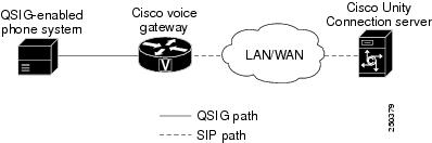
This integration uses a Cisco ISR voice gateway and a LAN or WAN to connect Cisco Unity Connection and a QSIG-enabled phone system. The Cisco ISR voice gateway converts the QSIG communications to SIP. Figure 1 shows the required connections.

Figure 1 Connections Between the Phone System and Cisco Unity Connection

Call Information

The QSIG-enabled phone system integration sends the following information with forwarded calls:

The extension of the called party

The extension of the calling party (for internal calls) or the phone number of the calling party (if it is an external call and the system uses caller ID)

The reason for the forward (the extension is busy, does not answer, or is set to forward all calls)

Cisco Unity Connection uses this information to answer the call appropriately. For example, a call forwarded to Cisco Unity Connection is answered with the personal greeting of the user. If the phone system routes the call to Cisco Unity Connection without this information, Cisco Unity Connection answers with the opening greeting.

Integration Functionality

The QSIG-enabled phone system integration with Cisco Unity Connection provides the following features:

Call forward to personal greeting

Call forward to busy greeting

Caller ID

Easy message access (a user can retrieve messages without entering an ID because Cisco Unity Connection identifies the user based on the extension from which the call originated; a password may be required)

Identified user messaging (Cisco Unity Connection identifies the user who leaves a message during a forwarded internal call, based on the extension from which the call originated)

Message waiting indication (MWI)

Integrations with Multiple Phone Systems

When Cisco Unity Connection is installed as Cisco Unified Communications Manager Business Edition (CMBE)—on the same server with Cisco Unified Communications Manager—Cisco Unity Connection cannot be integrated with multiple phone systems at one time.

When Cisco Unity Connection is not installed as Cisco Unified CMBE, Cisco Unity Connection can be integrated with multiple phone systems at one time. For information on and instructions for integrating Cisco Unity Connection with multiple phone systems, refer to the Multiple Phone System Integration Guide for Cisco Unity Connection at http://www.cisco.com/en/US/products/ps6509/products_installation_and_configuration_guides_list.html.

Planning How the Voice Messaging Ports Will Be Used by Cisco Unity Connection

Before programming the phone system, you need to plan how the voice messaging ports will be used by Cisco Unity Connection. The following considerations will affect the programming for the phone system (for example, setting up the hunt group or call forwarding for the voice messaging ports):

The number of voice messaging ports installed.

The number of voice messaging ports that will answer calls.

The number of voice messaging ports that will only dial out, for example, to send message notification, to set message waiting indicators (MWIs), and to make telephone record and playback (TRAP) connections.


Note The Cisco ISR voice gateway will perform transfers by hairpinning two independent calls across two b-channels on the QSIG trunk. Hairpinned calls will use more QSIG channels in comparison to the number of Cisco Unity Connection voice messaging ports that are available to answer calls.

Release (blind) transfers that are forwarded back to Cisco Unity Connection will use three b-channels for the remainder of the call. However, supervised transfers pull back the consulting call when the target is unavailable so that only one b-channel is used for the remainder of the call.


The following table describes the voice messaging port settings in Cisco Unity Connection that can be set on Telephony Integrations > Port of Cisco Unity Connection Administration.

Table 1 Settings for the Voice Messaging Ports 

Field
Considerations

Enabled

Check this check box to enable the port. The port is enabled during normal operation.

Uncheck this check box to disable the port. When the port is disabled, calls to the port get a ringing tone but are not answered. Typically, the port is disabled only by the installer during testing.

Answer Calls

Check this check box to designate the port for answering calls. These calls can be incoming calls from unidentified callers or from users.


Caution All voice messaging ports connecting to the Cisco ISR voice gateway must have the Answer Calls box checked. Otherwise, calls to Connection may not be answered.

Perform Message Notification

Check this check box to designate the port for notifying users of messages. Assign Perform Message Notification to the least busy ports.

Send MWI Requests

Check this check box to designate the port for turning MWIs on and off. Assign Send MWI Requests to the least busy ports.

Allow TRAP Connections

Check this check box so that users can use the port for recording and playback through the phone in Cisco Unity Connection web applications. Assign Allow TRAP Connections to the least busy ports.


The Number of Voice Messaging Ports to Install

The number of voice messaging ports to install depends on numerous factors, including:

The number of calls Cisco Unity Connection will answer when call traffic is at its peak.

The expected length of each message that callers will record and that users will listen to.

The number of users.

The number of calls made for message notification.

The number of MWIs that will be activated when call traffic is at its peak.

The number of TRAP connections needed when call traffic is at its peak. (TRAP connections are used by Cisco Unity Connection web applications to play back and record over the phone.)

The number of calls that will use the automated attendant and call handlers when call traffic is at its peak.

It is best to install only the number of voice messaging ports that are needed so that system resources are not allocated to unused ports.

The Number of Voice Messaging Ports That Will Answer Calls

The calls that the voice messaging ports answer can be incoming calls from unidentified callers or from users. Assign all of the voice messaging ports to answer calls.

You can set voice messaging ports to both answer calls and to dial out (for example, to send message notifications).


Note The Cisco ISR voice gateway will perform transfers by hairpinning two independent calls across two b-channels on the QSIG trunk. Hairpinned calls will use more QSIG channels in comparison to the number of Cisco Unity Connection voice messaging ports that are available to answer calls. If your system uses Cisco Unity Connection auto-attendant transfers, you must provision a larger number of QSIG b-channels than the number of Cisco Unity Connection voice messaging ports that will answer calls.


The Number of Voice Messaging Ports That Will Dial Out

Ports that will only dial out can do one or more of the following:

Notify users by phone, pager, or e-mail of messages that have arrived.

Turn MWIs on and off for user extensions.

Make a TRAP connection so that users can use the phone as a recording and playback device in Cisco Unity Connection web applications.

Preparing for Programming the Phone System

Record your decisions about the voice messaging ports to guide you in programming the phone system.

Programming the QSIG-Enabled Phone System

For information on provisioning the phone system for QSIG interoperability, see the phone system documentation.

Note that you must program each extension to forward calls to the pilot number assigned to the voice messaging ports, based on one of the call transfer types shown in Table 2.

Table 2 Call Transfer Types 

Transfer Types
Usage

Release transfer
(blind transfer)

Program the phone to forward calls to the pilot number when:

The extension is busy

The call is not answered

Supervised transfer

Program the phone to forward calls to the pilot number only when the call is not answered (on the phone system, the number of rings before forwarding must be more than the number of rings to supervise the call). Confirm that call forwarding is disabled when the extension is busy.


Configuring the Cisco ISR Voice Gateway


Note If the Cisco Unity Connection SIP Port setting will not be 5060 (for example, if it is set to 5061), you must change the SIP port that the Cisco ISR voice gateway uses. You can use a command similar to the following:
dial-peer voice 1 voip
 session protocol sipv2
 session target ipv4:10.00.00.00:5061


Creating a New Integration with the QSIG-enabled Phone System

After ensuring that QSIG-enabled phone system and Cisco Unity Connection are ready for the integration, do the following procedure to set up the integration and to enter the port settings.

To Create an Integration


Step 1 Log on to Cisco Unity Connection Administration.

Step 2 In Cisco Unity Connection Administration, expand Telephony Integrations, then click Phone System.

Step 3 On the Search Phone Systems page, on the Phone System menu, click New Phone System. The Phone System Integration Wizard appears.

Step 4 On the Select Phone System Manufacturer page, in the Manufacturer field, click QSIG/DPNSS and click Next.

Step 5 On the Select Phone System Model page, in the Model field, click QSIG/DPNSS and click Next.

Step 6 On the Set Up Phone System page, in the Phone System Name field, enter the descriptive name that you want, and click Next.

Step 7 On the Select Port Group Template page, in the Port Group Template field, click one of the following:

Cisco ISR Voice Gateway to QSIG PBX, if the option is available.

Cisco 2200 EGW to QSIG/DPNSS PBX otherwise.

Then click Next.

Step 8 On the Set Up Port Group page, enter the following settings and click Next.

Table 3 Settings for the Set Up Port Group Page 

Field
Setting

Port Group Name

Enter a descriptive name for the port group.

Contact Line Name

Enter the voice messaging pilot number that matches the dial plan configuration of the gateway.

Authenticate with SIP Proxy Server

Confirm that this check box is unchecked.

Authentication User Name

Leave this field blank.

Authentication Password

Leave this field blank.

Cisco Unity Connection SIP Port

Enter the SIP port on Cisco Unity Connection that the gateway will connect to. We recommend that you use the default setting.


Caution This setting must match the port specified in the "session target ipv4" command under the SIP VoIP dial-peer configured on the Cisco ISR voice gateway. Otherwise, the integration will not function correctly.

Number of Ports

Enter the number of voice messaging ports that you want to create in this port group.

IP Address or Host Name

Enter the IP address (or host name) of the primary gateway that you are connecting to Cisco Unity Connection.

Test Address

Click this button to test the IP address (or host name) that you entered. The results of the test appear in the field to the right of the button.


Note Even though the integration is successful, the test may fail on networks where the "ping" command is disabled or ignored, or when the gateway is not running.


Port

Enter the IP port of the primary gateway that you are connecting to Cisco Unity Connection. We recommend that you use the default setting.


Caution This setting must match the port setting of the gateway. Otherwise, the integration will not function correctly.

Step 9 On the Confirm Phone System Settings page, confirm the settings that you have entered and click Finish.

Step 10 On the Phone System Creation Summary page, click Close.

Step 11 In Cisco Unity Connection Administration, expand Telephony Integrations, then click Port.

Step 12 On the Search Ports page, click the display name of the first voice messaging port that you created for this phone system integration.


Note By default, the display names for the voice messaging ports are composed of the port group display name followed by incrementing numbers.


Step 13 On the Port Basics page, enter the following settings. The fields in the following table are the ones that you can change.

Table 4 Settings for the Voice Messaging Ports 

Field
Considerations

Enabled

Check this check box to enable the port. The port is enabled during normal operation.

Uncheck this check box to disable the port. When the port is disabled, calls to the port get a ringing tone but are not answered. Typically, the port is disabled only by the installer during testing.

Answer Calls

Check this check box to designate the port for answering calls. These calls can be incoming calls from unidentified callers or from users.

Perform Message Notification

Check this check box to designate the port for notifying users of messages. Assign Perform Message Notification to the least busy ports.

Send MWI Requests

Check this check box to designate the port for turning MWIs on and off. Assign Send MWI Requests to the least busy ports.

Allow TRAP Connections

Check this check box so that users can use the port for recording and playback through the phone in Cisco Unity Connection web applications. Assign Allow TRAP Connections to the least busy ports.


Step 14 Click Save.

Step 15 Click Next.

Step 16 Repeat Step 13 through Step 15 for all remaining voice messaging ports for the phone system.

Step 17 If another phone system integration exists, in Cisco Unity Connection Administration, expand Telephony Integrations, then click Trunk. Otherwise, skip to Step 21.

Step 18 On the Search Phone System Trunks page, on the Phone System Trunk menu, click New Phone System Trunk.

Step 19 On the New Phone System Trunk page, enter the following settings for the phone system trunk and click Save.

Table 5 Settings for the Phone System Trunk 

Field
Setting

From Phone System

Click the display name of the phone system that you are creating a trunk for.

To Phone System

Click the display name of the previously existing phone system that the trunk will connect to.

Trunk Access Code

Enter the extra digits that Cisco Unity Connection must dial to transfer calls through the gateway to extensions on the previously existing phone system.


Step 20 Repeat Step 18 and Step 19 for all remaining phone system trunks that you want to create.

Step 21 If prompted to restart the Connection Conversation Manager service, do the following substeps. Otherwise, continue to Step 22.

a. In the Navigation drop-down list, click Cisco Unity Connection Serviceability and click Go.

b. On the Cisco Unity Connection Serviceability page, on the Tools menu, click Control Center - Feature Services.

c. On the Control Center - Feature Services page, in the Select Server drop-down list, click the name of the Cisco Unity Connection server and click Go.

d. Under Cisco Unity Connection Services, click Connection Conversation Manager.

e. At the top of the page, click Restart.

f. When prompted to confirm restarting the service, click Yes.

g. In the Navigation drop-down list, click Cisco Unity Connection Administration and click Go.

h. In Cisco Unity Connection Administration, expand Telephony Integrations, then click Phone System.

Step 22 In the Related Links drop-down list, click Check Telephony Configuration and click Go to confirm the phone system integration settings.

If the test is not successful, the Task Execution Results displays one or more messages with troubleshooting steps. After correcting the problems, test the connection again.

Step 23 In the Task Execution Results window, click Close.

Step 24 Log off Cisco Unity Connection Administration.


Testing the Integration

To test whether Cisco Unity Connection and the phone system are integrated correctly, do the following procedures in the order listed.

If any of the steps indicate a failure, see the following documentation as applicable:

The installation guide for the phone system.

Troubleshooting Guide for Cisco Unity Connection, available at http://www.cisco.com/en/US/products/ps6509/prod_troubleshooting_guides_list.html.

The setup information earlier in this guide.

To Set Up the Test Configuration


Step 1 Set up two test extensions (Phone 1 and Phone 2) on the same phone system that Cisco Unity Connection is connected to.

Step 2 Set Phone 1 to forward calls to the Cisco Unity Connection pilot number when calls are not answered.


Caution The phone system must forward calls to the Cisco Unity Connection pilot number in no fewer than four rings. Otherwise, the test may fail.

Step 3 To create a test user for testing, in Cisco Unity Connection Administration, expand Users, then click Users.

Step 4 On the Search Users page, on the User menu, click Add New.

Step 5 On the New User page, enter the following settings.

Table 6 Settings for the New User Page 

Field
Setting

User Type

Click User with Voice Mailbox.

Based on Template

Click the applicable user template.

Alias

Enter testuser.

First Name

Enter Test.

Last Name

Enter User.

Display Name

Enter Test User.

Extension

Enter the extension of Phone 1.


Step 6 Click Save.

Step 7 On the Edit User Basics page, in the Voice Name field, record a voice name for the test user.

Step 8 In the Phone System field, confirm that the phone system selected is the phone system that Phone 1 is connected to.

Step 9 Uncheck the Set for Self-enrollment at Next Login check box.

Step 10 Click Save.

Step 11 On the Edit menu, click Message Waiting Indicators.

Step 12 On the Message Waiting Indicators page, click the message waiting indicator. If no message waiting indication is in the table, click Add New.

Step 13 On the Edit Message Waiting Indicator page, enter the following settings.

Table 7 Settings for the Edit MWI Page 

Field
Setting

Enabled

Check this check box to enable MWIs for the test user.

Display Name

Accept the default or enter a different name.

Inherit User's Extension

Check this check box to enable MWIs on Phone 1.


Step 14 Click Save.

Step 15 On the Edit menu, click Transfer Options.

Step 16 On the Transfer Options page, click the active option.

Step 17 On the Edit Transfer Option page, under Transfer Action, click the Extension option and enter the extension of Phone 1.

Step 18 In the Transfer Type field, click Release to Switch.

Step 19 Click Save.

Step 20 Minimize the Cisco Unity Connection Administration window.

Do not close the Cisco Unity Connection Administration window because you will use it again in a later procedure.

Step 21 Log on to the Real-Time Monitoring Tool (RTMT).

Step 22 On the Unity Connection menu, click Port Monitor. The Port Monitor tool appears in the right pane.

Step 23 In the right pane, click Start Polling. The Port Monitor will display which port is handling the calls that you will make.


To Test an External Call with Release Transfer


Step 1 From Phone 2, enter the access code necessary to get an outside line, then enter the number outside callers use to dial directly to Cisco Unity Connection.

Step 2 In the Port Monitor, note which port handles this call.

Step 3 When you hear the opening greeting, enter the extension for Phone 1. Hearing the opening greeting means that the port is configured correctly.

Step 4 Confirm that Phone 1 rings and that you hear a ringback tone on Phone 2. Hearing a ringback tone means that Cisco Unity Connection correctly released the call and transferred it to Phone 1.

Step 5 Leaving Phone 1 unanswered, confirm that the state of the port handling the call changes to "Idle." This state means that release transfer is successful.

Step 6 Confirm that, after the number of rings that the phone system is set to wait, the call is forwarded to Cisco Unity Connection and that you hear the greeting for the test user. Hearing the greeting means that the phone system forwarded the unanswered call and the call-forward information to Cisco Unity Connection, which correctly interpreted the information.

Step 7 On the Port Monitor, note which port handles this call.

Step 8 Leave a message for the test user and hang up Phone 2.

Step 9 In the Port Monitor, confirm that the state of the port handling the call changes to "Idle." This state means that the port was successfully released when the call ended.

Step 10 Confirm that the MWI on Phone 1 is activated. The activated MWI means that the phone system and Cisco Unity Connection are successfully integrated for turning on MWIs.


To Test Listening to Messages


Step 1 From Phone 1, enter the internal pilot number for Cisco Unity Connection.

Step 2 When asked for your password, enter the password for the test user. Hearing the request for your password means that the phone system sent the necessary call information to Cisco Unity Connection, which correctly interpreted the information.

Step 3 Confirm that you hear the recorded voice name for the test user (if you did not record a voice name for the test user, you will hear the extension number for Phone 1). Hearing the voice name means that Cisco Unity Connection correctly identified the user by the extension.

Step 4 Listen to the message.

Step 5 After listening to the message, delete the message.

Step 6 Confirm that the MWI on Phone 1 is deactivated. The deactivated MWI means that the phone system and Cisco Unity Connection are successfully integrated for turning off MWIs.

Step 7 Hang up Phone 1.

Step 8 On the Port Monitor, confirm that the state of the port handling the call changes to "Idle." This state means that the port was successfully released when the call ended.


To Set Up Supervised Transfer on Cisco Unity Connection


Step 1 In Cisco Unity Connection Administration, on the Edit Transfer Option page for the test user, in the Transfer Type field, click Supervise Transfer.

Step 2 In the Rings to Wait For field, enter 3.

Step 3 Click Save.

Step 4 Minimize the Cisco Unity Connection Administration window.

Do not close the Cisco Unity Connection Administration window because you will use it again in a later procedure.


To Test Supervised Transfer


Step 1 From Phone 2, enter the access code necessary to get an outside line, then enter the number outside callers use to dial directly to Cisco Unity Connection.

Step 2 On the Port Monitor, note which port handles this call.

Step 3 When you hear the opening greeting, enter the extension for Phone 1. Hearing the opening greeting means that the port is configured correctly.

Step 4 Confirm that Phone 1 rings and that you do not hear a ringback tone on Phone 2. Instead, you should hear the indication your phone system uses to mean that the call is on hold (for example, music).

Step 5 Leaving Phone 1 unanswered, confirm that the state of the port handling the call remains "Busy." This state and hearing an indication that you are on hold mean that Cisco Unity Connection is supervising the transfer.

Step 6 Confirm that, after three rings, you hear the greeting for the test user. Hearing the greeting means that Cisco Unity Connection successfully recalled the supervised-transfer call.

Step 7 During the greeting, hang up Phone 2.

Step 8 On the Port Monitor, confirm that the state of the port handling the call changes to "Idle." This state means that the port was successfully released when the call ended.

Step 9 Click Stop Polling.

Step 10 Exit RTMT.


To Delete the Test User


Step 1 In Cisco Unity Connection Administration, expand Users, then click Users.

Step 2 On the Search Users page, check the check box to the left of the test user.

Step 3 Click Delete Selected.


(Multiple Integrations Only) Adding New User Templates

When you create the first phone system integration, this phone system is automatically selected in the default user template. The users that you add after creating this phone system integration will be assigned to this phone system by default.

However, for each additional phone system integration that you create, you must add the applicable new user templates that will assign users to the new phone system. You must add the new templates before you add new users who will be assigned to the new phone system.

For details on adding new user templates, refer to the "Adding, Changing, or Deleting an Account Template" chapter in the User Moves, Adds, and Changes Guide for Cisco Unity Connection at http://www.cisco.com/en/US/products/ps6509/prod_maintenance_guides_list.html.

For details on selecting a user template when adding a new user, refer to the applicable chapter for adding user accounts in the User Moves, Adds, and Changes Guide for Cisco Unity Connection at http://www.cisco.com/en/US/products/ps6509/prod_maintenance_guides_list.html.


Appendix: Documentation and Technical Assistance


Documentation Conventions

The QSIG-Enabled Phone System with Cisco ISR Voice Gateway Integration Guide for Cisco Unity Connection 2.x uses the following conventions.

Table 8 QSIG-Enabled Phone System with Cisco ISR Voice Gateway Integration Guide for Cisco Unity Connection 2.x Conventions 

Convention
Description

boldfaced text

Boldfaced text is used for:

Key and button names. (Example: Click OK.)

Information that you enter. (Example: Enter Administrator in the User Name box.)

< >

(angle brackets)

Angle brackets are used around parameters for which you supply a value. (Example: In the Command Prompt window, enter ping <IP address>.)

-

(hyphen)

Hyphens separate keys that must be pressed simultaneously. (Example: Press Ctrl-Alt-Delete.)

>

(right angle
bracket)

A right angle bracket is used to separate selections that you make:

On menus. (Example: On the Windows Start menu, click Programs > Cisco Unified Serviceability > Real-Time Monitoring Tool.)

In the navigation bar of Cisco Unity Connection Administration. (Example: In Cisco Unity Connection Administration, expand System Settings > Advanced.)

[x]

(square brackets)

Square brackets enclose an optional element (keyword or argument). (Example: [reg-e164])

[x | y]

(vertical line)

Square brackets enclosing keywords or arguments separated by a vertical line indicate an optional choice. (Example: [transport tcp | transport udp])

{x | y}

(braces)

Braces enclosing keywords or arguments separated by a vertical line indicate a required choice. (Example: {tcp | udp})


The QSIG-Enabled Phone System with Cisco ISR Voice Gateway Integration Guide for Cisco Unity Connection 2.x also uses the following conventions:


Note Means reader take note. Notes contain helpful suggestions or references to material not covered in the document.


Caution Means reader be careful. In this situation, you might do something that could result in equipment damage or loss of data.

For descriptions and URLs of Cisco Unity Connection documentation on Cisco.com, see the Documentation Guide for Cisco Unity Connection. The document is shipped with Cisco Unity Connection and is available at http://www.cisco.com/en/US/products/ps6509/products_documentation_roadmaps_list.html.

Obtaining Documentation and Submitting a Service Request

For information on obtaining documentation, submitting a service request, and gathering additional information, see the monthly What's New in Cisco Product Documentation, which also lists all new and revised Cisco technical documentation, at:

http://www.cisco.com/en/US/docs/general/whatsnew/whatsnew.html

Subscribe to the What's New in Cisco Product Documentation as a Really Simple Syndication (RSS) feed and set content to be delivered directly to your desktop using a reader application. The RSS feeds are a free service and Cisco currently supports RSS version 2.0.


[an error occurred while processing this directive]