Table Of Contents
Connecting DC Power
DC Power Overview
Connecting DC Power to a CDE200
Disconnecting Power and Replacing a PM on a CDE200
Connecting DC Power to a CDE300
Disconnecting Power and Replacing a PM on a CDE300
Connecting DC Power to a CDE400
Disconnecting Power and Replacing a PM on a CDE400
DC Power Cable Connector and Pinouts
Connecting DC Power
This appendix provides the information for connecting DC power to a CDE. This appendix includes the following sections:
•
DC Power Overview
•
Connecting DC Power to a CDE200
•
Connecting DC Power to a CDE300
•
Connecting DC Power to a CDE400
•
DC Power Cable Connector and Pinouts
Note
Prior to connecting DC Power to a CDE, consult the Regulatory Compliance and Safety Information for the Cisco Content Delivery Engine 100/200/300/400 document for important regulation and safety information.
DC Power Overview
The CDE200, CDE300 and CDE400 can accept DC power (CDE100s do not have a DC power option). The CDEs can accept power from a -48 VDC (-42 to -56 VDC) source that connects to one (primary) or two (secondary/redundant) -48 VDC power modules (PMs). Each DC PM must be connected to a dedicated 60A regulated source. Figure D-1 shows a DC PM for a CDE200.
Figure D-1 DC Power Module for a CDE200
Note
In this chapter, the power supply is referred to as a "power module."
Connecting DC Power to a CDE200
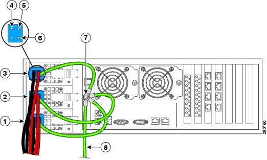
The CDE200 ships fully populated with two DC PMs installed in the PM slots on the rear of the chassis; two DC power cables are shipped separately. The chassis has one building ground stud and one PM ground stud. The minimum cabling requirement for connecting DC power to a CDE200 is one PM connect, but it is recommended that you use both PM connects. Figure D-2 shows the rear view of a fully-connected CDE200 and provides the location of the ground studs and PMs.
Figure D-2 CDE200 Rear Panel
1
|
PM 1
|
6
|
PM ground stud
|
2
|
PM 2
|
7
|
Building ground stud
|
3
|
-48 VDC
|
8
|
Building ground wire
|
4
|
+Return
|
9
|
DC power wires
|
5
|
PM ground
|
|
Connect DC power to the CDE200 by performing the following steps:
Caution 
Make sure the DC power wires are not attached to the DC power source until all the ground wires are connected on the CDE.
Step 1
Insert a blue DC power cable connector into the blue port on each PM, making sure it is completely seated.
Step 2
Attach the ground wires from PM 1 and PM 2 to the PM ground stud:
a.
Remove the nut and star washers from the PM ground stud.
b.
Place the ring lug at the end of the ground wires (green and yellow) attached to the DC power cable connector over the PM ground stud in the following order and secure with the nut (see Figure D-3):
–
Star washer
–
PM ground ring lug 1
–
PM ground ring lug 2
–
Star washer
–
Nut
Note
Install star washers between the ring lug and chassis ground connection so that the star washers dig into the metalwork finish and make a good ground bond. Use a wrench to tighten the nut and secure the connection.
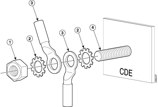
Figure D-3 CDE200 PM Ground Stud Order
1
|
Nut
|
3
|
PM ground ring lug
|
2
|
Star washer
|
4
|
PM ground stud
|
Step 3
Attach the building ground wire to the building ground stud (see Figure D-4).
Warning
The DC ground connection in the CDE serves as a functional earth point to maintain the full EMI and EMC integrity of the equipment. The purpose is to mitigate the damaging effects of electrostatic discharge. This connection should be installed by a trained service person and the equipment is to be installed per local code or local authority having jurisdiction (AHJ). The building ground wire should not exceed 3 meters in length and be sized similarity to the conductors used for the DC power connections (-48 VDC and +Return).
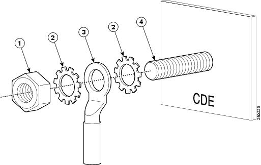
Figure D-4 CDE200 Building Ground Stud Order
1
|
Nut
|
3
|
Building ground ring lug
|
2
|
Star washer
|
4
|
Building ground stud
|
Step 4
Attach the +Return (red) and -48 VDC (black) DC power wires to your power source.
The CDE200 is now ready for use.
Disconnecting Power and Replacing a PM on a CDE200
Warning
The PM connectors and PMs are not hot-swappable. You must disconnect the power source from the building before disconnecting PM wires or removing PMs from a CDE.
Should you need to replace a PM, you must first disconnect DC power and remove the PM from the CDE chassis. Perform the following steps:
Step 1
Remove the +Return (red) and -48 VDC (black) DC power wires from your power source.
Step 2
Remove the PM ground wires (green and yellow) from the PM ground stud.
Step 3
Loosen the screw and press the latch to release the PM from the chassis. Pull the handle and gently slide the PM from the slot.
Step 4
Insert a new PM in the slot and make sure it is completely seated in the CDE.
Step 5
Reconnect the PM ground wires (green and yellow) to the PM ground stud as described in Step 2 of the "Connecting DC Power to a CDE200" section.
Step 6
Reconnect the +Return (red) and -48 VDC (black) DC power wires to your power source.
Connecting DC Power to a CDE300
The CDE300 ships fully populated with three DC PMs installed in the PM slots on the rear of the chassis; three DC power cables are shipped separately. The chassis has one ground stud that provides building and PM grounding. The minimum cabling requirement for connecting DC power to a CDE300 is two PM connects, but it is recommended that you use all three PM connects. Figure D-5 shows the rear view of a fully-connected CDE300 and provides the location of the studs and PMs.
Figure D-5 CDE300 Rear Panel
1
|
PM 1
|
5
|
+Return
|
2
|
PM 2
|
6
|
PM ground
|
3
|
PM 3
|
7
|
Building/PM ground stud
|
4
|
-48 VDC
|
8
|
Building ground wire
|
Connect DC power to the CDE300 by performing the following steps:
Caution 
Make sure the DC power wires are not attached to the DC power source until all the ground wires are connected on the CDE.
Step 1
Insert one blue DC power cable connector into the blue port on each PM, making sure it is completely seated.
Step 2
Remove the nut and star washers from the Building/PM ground stud.
Step 3
Place the ring lugs at the end of the ground wires (green and yellow) attached to the DC power cable connector over the Building/PM ground stud in the following order and secure with the nut (see Figure D-6):
Note
Fan the ring lugs and barrels so that they fit on the Building/PM ground stud (see Figure D-6).
–
Star washer
–
Building ground ring lug
–
Star washer
–
Nut
–
PM 1 ground ring lug
–
PM 2 ground ring lug
–
PM 3 ground ring lug
–
Star washer
–
Nut
Figure D-6 CDE300 Building/PM Ground Stud Order
1
|
Nut
|
4
|
Building ground ring lug
|
2
|
Star washer
|
5
|
Building/PM ground stud
|
3
|
PM ground ring lug
|
|
Note
Install star washers between the ring lug and chassis ground connection so that the star washers dig into the metalwork finish and make a good ground bond. Use a wrench to tighten the nut and secure the connection.
Warning
The DC ground connection in the CDE serves as a functional earth point to maintain the full EMI and EMC integrity of the equipment. The purpose is to mitigate the damaging effects of electrostatic discharge. This connection should be installed by a trained service person and the equipment is to be installed per local code or local authority having jurisdiction (AHJ). The building ground wire should not exceed 3 meters in length and be sized similarity to the conductors used for the DC power connections (-48 VDC and +Return).
Step 4
Attach the +Return (red) and -48 VDC (black) DC power wires to your power source.
The CDE300 is now ready for use.
Disconnecting Power and Replacing a PM on a CDE300
Warning
The PM connectors and PMs are not hot-swappable. You must disconnect the power source from the building before disconnecting PM wires or removing PMs from a CDE.
Should you need to replace a PM, you must first disconnect DC power and remove the PM from the CDE chassis. Perform the following steps:
Step 1
Remove the +Return (red) and -48 VDC (black) DC power wires from your power source.
Step 2
Remove the PM ground wires (green and yellow) from the Building/PM ground stud.
Step 3
Press the butterfly lever to release the CDE from the chassis. Pull the handle and gently slide the PM from the slot.
Step 4
Insert a new PM in the slot and make sure it is completely seated in the CDE.
Step 5
Reconnect the PM ground wires (green and yellow) to the PM ground stud as described in Step 3 of the "Connecting DC Power to a CDE300" section.
Step 6
Reconnect the +Return (red) and -48 VDC (black) DC power wires to your power source.
Connecting DC Power to a CDE400
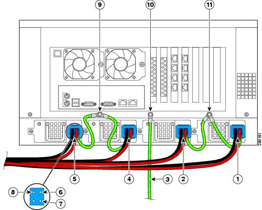
The CDE400 ships fully populated with four DC PMs installed in the PM slots on the rear of the chassis; four DC power cables are shipped separately. The chassis has one building ground stud and two PM ground studs. The minimum cabling requirement for connecting DC power to a CDE400 is three PM connects, but it is recommended that you use all four PM connects. Figure D-7 shows the rear view of a fully-connected CDE400 and provides the location of the studs and PMs.
Figure D-7 CDE400 Rear Panel
1
|
PM 4
|
7
|
PM ground
|
2
|
PM 3
|
8
|
-48 VDC
|
3
|
Building ground wire
|
9
|
PM ground stud 1
|
4
|
PM 2
|
10
|
Building ground stud
|
5
|
PM 1
|
11
|
PM ground stud 2
|
6
|
+Return
|
|
Connect DC power to the CDE400 by performing the following steps:
Caution 
Make sure the DC power wires are not attached to the DC power source until all the ground wires are connected on the CDE.
Step 1
Insert one blue DC power cable connector into the blue port on each PM, making sure it is completely seated.
Step 2
Attach the ground wires from the PMs to the PM ground studs:
a.
Remove the nut and star washers from the PM 1 ground stud.
b.
Place the ring lug at the end of the ground wires (green and yellow) attached to the DC power cable connectors in PM 1 and PM 2 over PM ground stud 1 in the following order and secure with the nut (see Figure D-8):
–
Star washer
–
PM 1 ground ring lug
–
PM 2 ground ring lug
–
Star washer
–
Nut
Note
Install star washers between the ring lug and chassis ground connection so that the star washers dig into the metalwork finish and make a good ground bond. Use a wrench to tighten the nut and secure the connection.
Figure D-8 CDE400 PM Ground Stud Order
1
|
Nut
|
3
|
PM ground ring lugs
|
2
|
Star washer
|
4
|
PM ground stud
|
c.
Remove the nut and star washers from the PM 2 ground stud.
d.
Place the ring lug at the end of the ground wires (green and yellow) attached to the DC power cable connectors in PM 3 and PM 4 over PM ground stud 2 in the following order and secure with the nut (see Figure D-8):
–
Star washer
–
PM 3 ground ring lug
–
PM 4 ground ring lug
–
Star washer
–
Nut
Step 3
Attach the building ground wire to the building ground stud (see Figure D-4).
Warning
The DC ground connection in the CDE serves as a functional earth point to maintain the full EMI and EMC integrity of the equipment. The purpose is to mitigate the damaging effects of electrostatic discharge. This connection should be installed by a trained service person and the equipment is to be installed per local code or local authority having jurisdiction (AHJ). The building ground wire should not exceed 3 meters in length and be sized similarity to the conductors used for the DC power connections (-48 VDC and +Return).
Step 4
Attach the +Return (red) and -48 VDC (black) DC power wires to your power source.
The CDE400 is now ready for use.
Disconnecting Power and Replacing a PM on a CDE400
Warning
The PM connectors and PMs are not hot-swappable. You must disconnect the power source from the building before disconnecting PM wires or removing PMs from a CDE.
Should you need to replace a PM, you must first disconnect DC power and remove the PM from the CDE chassis. Perform the following steps:
Step 1
Remove the +Return (red) and -48 VDC (black) power wires from your power source.
Step 2
Remove the PM ground wires (green and yellow) from the PM ground studs.
Step 3
Loosen the screw on the PM to release it from the chassis. Pull the handle and gently slide the PM from the slot.
Step 4
Insert a new PM in the slot and make sure it is completely seated in the CDE.
Step 5
Reconnect the PM ground wires (green and yellow) to the PM ground studs as described in Step 2 of the "Connecting DC Power to a CDE400" section.
Step 6
Reconnect the +Return (red) and -48 VDC (black) DC power wires to your power source.
DC Power Cable Connector and Pinouts
The DC power cable connector (see Figure D-9) ships with the CDEs when you order the DC power option. This is the only DC power connector you should use to connect power to the CDEs in your system.
Figure D-9 DC Power Cable and Pinouts
1
|
+Return
|
4
|
PM ground wire and ring lug
|
2
|
-48 VDC
|
5
|
-48 VDC wire and ring lug
|
3
|
PM ground
|
6
|
+Return wire and ring lug
|