Table Of Contents
About Cisco Validated Design (CVD) Program
FlexPod with Microsoft Hyper-V Windows Server 2012 Deployment Guide
Nexus 5548UP Deployment Procedure
Initial Cisco Nexus 5548UP Switch Configuration
Enable Appropriate Cisco Nexus Features
Add Individual Port Descriptions for Troubleshooting
Create Necessary Port Channels
Add Port Channel Configurations
Configure Virtual Port Channels
Link into Existing Network Infrastructure
NetApp FAS3240A Deployment Procedure - Part 1
Complete the Configuration Worksheet
Assign Controller Disk Ownership and initialize storage
Upgrade the Service Processor on Each Node to the Latest Release
Storage Controller Active-Active Configuration
Joining a Windows Domain (optional)
Install Remaining Required Licenses and Enable MultiStore
Cisco Unified Computing System Deployment Procedure
Perform Initial Setup of the Cisco UCS 6248 Fabric Interconnects
Add a Block of IP Addresses for KVM Access
Enable Server and Uplink Ports
Acknowledge the Cisco UCS Chassis
Create Uplink Port Channels to the Cisco Nexus 5548 Switches
Create VSANs and FCoE Port Channels
Create a FC Adapter Policy for NetApp Storage Arrays
Create a Firmware Management Package
Create Firmware Package Policy
Set Jumbo Frames and Enable Quality of Service in Cisco UCS Fabric
Create a Local Disk Configuration Policy
Create a Server Pool Qualification Policy
Create Dynamic vNIC Connection Policy for VM-FEX (SR-IOV)
Create vNIC/HBA Placement Policy for Virtual Machine Infrastructure Hosts
Create vHBA Templates for Fabric A and B
Create Service Profile Templates
Create VM-FEX Port Profiles and Virtual Switch Clusters
Add More Server Blades to the FlexPod Unit
Create Zones for Each Service Profile (Part 1)
NetApp FAS3240A Deployment Procedure - Part 2
Microsoft Windows Server 2012 Hyper-V Deployment Procedure
Setup the Windows Server 2012 install
Install Windows Roles and features
Configure Windows Networking for FlexPod
Create Zones for Each Service Profile (Part 2)
Install Cisco Virtual Switch Forwarding Extensions for Hyper-V
Create Hyper-V Virtual Network Switches
Domain Controller Virtual Machines
Install NetApp SnapManager for Hyper-V
Install VM-FEX Port Profile Management Utilities in Hyper-V
Configure Live Migration network.
Change the Cluster to Use a Quorum Disk.
Deploying a Virtual Machine with VM-FEX
Attach Port Profile to the Virtual Machine
Install Windows and Cisco VF VIC Driver
Install Windows Features in the Virtual Machine
Configure Windows Host iSCSI initiator
Install NetApp Utilities in the Virtual Machine
Create and Map iSCSI LUNs using SnapDrive
Installing Cisco UCS PowerTool
Appendix B: Installing the DataONTAP PowerShell Toolkit
Appendix C: Creating Domain Controller Virtual Machine (Optional)
Create VHD for Domain Controller Virtual Machine.
Install Windows in a Domain Controller Virtual Machine
Install Active Directory Services
FlexPod Data Center with Microsoft Hyper-V
Windows Server 2012 with 7-ModeDeployment Guide for FlexPod with Microsoft Hyper-V Windows Server 2012 with Data ONTAP 8.1.2 Operating in 7-ModeLast Updated: November 22, 2013
Building Architectures to Solve Business Problems
About the Authors
Mike Mankovsky, Technical Leader, Cisco SystemsMike Mankovsky is a Cisco Unified Computing System architect, focusing on Microsoft solutions with extensive experience in Hyper-V, storage systems, and Microsoft Exchange Server. He has expert product knowledge in Microsoft Windows storage technologies and data protection technologies.
Glenn Sizemore, Technical Marketing Engineer, NetApp
Glenn Sizemore is a Technical Marketing Engineer in the Microsoft Solutions Group at NetApp, where he specializes in Cloud and Automation. Since joining NetApp, Glenn has delivered a variety of Microsoft based solutions ranging from general best practice guidance to co-authoring the NetApp Hyper-V Cloud Fast Track with Cisco reference architecture.
About Cisco Validated Design (CVD) Program
The CVD program consists of systems and solutions designed, tested, and documented to facilitate faster, more reliable, and more predictable customer deployments. For more information visit:
http://www.cisco.com/go/designzone
ALL DESIGNS, SPECIFICATIONS, STATEMENTS, INFORMATION, AND RECOMMENDATIONS (COLLECTIVELY, "DESIGNS") IN THIS MANUAL ARE PRESENTED "AS IS," WITH ALL FAULTS. CISCO AND ITS SUPPLIERS DISCLAIM ALL WARRANTIES, INCLUDING, WITHOUT LIMITATION, THE WARRANTY OF MERCHANTABILITY, FITNESS FOR A PARTICULAR PURPOSE AND NONINFRINGEMENT OR ARISING FROM A COURSE OF DEALING, USAGE, OR TRADE PRACTICE. IN NO EVENT SHALL CISCO OR ITS SUPPLIERS BE LIABLE FOR ANY INDIRECT, SPECIAL, CONSEQUENTIAL, OR INCIDENTAL DAMAGES, INCLUDING, WITHOUT LIMITATION, LOST PROFITS OR LOSS OR DAMAGE TO DATA ARISING OUT OF THE USE OR INABILITY TO USE THE DESIGNS, EVEN IF CISCO OR ITS SUPPLIERS HAVE BEEN ADVISED OF THE POSSIBILITY OF SUCH DAMAGES.
THE DESIGNS ARE SUBJECT TO CHANGE WITHOUT NOTICE. USERS ARE SOLELY RESPONSIBLE FOR THEIR APPLICATION OF THE DESIGNS. THE DESIGNS DO NOT CONSTITUTE THE TECHNICAL OR OTHER PROFESSIONAL ADVICE OF CISCO, ITS SUPPLIERS OR PARTNERS. USERS SHOULD CONSULT THEIR OWN TECHNICAL ADVISORS BEFORE IMPLEMENTING THE DESIGNS. RESULTS MAY VARY DEPENDING ON FACTORS NOT TESTED BY CISCO.
The Cisco implementation of TCP header compression is an adaptation of a program developed by the University of California, Berkeley (UCB) as part of UCB's public domain version of the UNIX operating system. All rights reserved. Copyright © 1981, Regents of the University of California.
Cisco and the Cisco Logo are trademarks of Cisco Systems, Inc. and/or its affiliates in the U.S. and other countries. A listing of Cisco's trademarks can be found at http://www.cisco.com/go/trademarks. Third party trademarks mentioned are the property of their respective owners. The use of the word partner does not imply a partnership relationship between Cisco and any other company. (1005R)
Any Internet Protocol (IP) addresses and phone numbers used in this document are not intended to be actual addresses and phone numbers. Any examples, command display output, network topology diagrams, and other figures included in the document are shown for illustrative purposes only. Any use of actual IP addresses or phone numbers in illustrative content is unintentional and coincidental.
© 2013 Cisco Systems, Inc. All rights reserved.
FlexPod with Microsoft Hyper-V Windows Server 2012 Deployment Guide
Reference Architecture
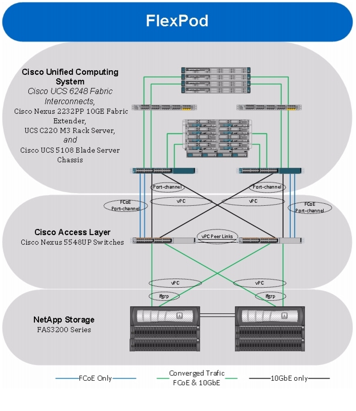
FlexPod architecture is highly modular, or pod-like. Although each customer's FlexPod unit might vary in its exact configuration, after a FlexPod unit is built, it can easily be scaled as requirements and demands change. This includes both scaling up (adding additional resources within a FlexPod unit) and scaling out (adding additional FlexPod units).
Specifically, FlexPod is a defined set of hardware and software that serves as an integrated foundation for all virtualization solutions. FlexPod validated with Microsoft Server 2012 Hyper-V includes NetApp® FAS3200 Series storage, Cisco Nexus® 5500 Series network switches, the Cisco Unified Computing Systems™ (Cisco UCS™) platforms, and Microsoft virtualization software in a single package. The computing and storage can fit in one data center rack with networking residing in a separate rack or deployed according to a customer's data center design. Due to port density, the networking components can accommodate multiple configurations of this kind.
Figure 1 Architecture overview
The reference configuration shown in Figure 1 includes:
•
Two Cisco Nexus 5548UP Switches
•
•
•
•
•
Storage is provided by a NetApp FAS3240A with accompanying disk shelves. All systems and fabric links feature redundancy and provide end-to-end high availability. For server virtualization, the deployment includes Hyper-V. Although this is the base design, each of the components can be scaled flexibly to support specific business requirements. For example, more (or different) blades and chassis could be deployed to increase compute capacity, additional disk shelves could be deployed to improve I/O capacity and throughput, or special hardware or software features could be added to introduce new features.
For more information on FlexPod for Windows Server 2012 Hyper-V design choices and deployment best practices, see FlexPod for Windows Server 2012 Hyper-V Design Guide:
http://www.cisco.com/en/US/solutions/collateral/ns340/ns517/ns224/ns944/whitepaper__c07-727095.html
Note
The remainder of this document guides you through the low-level steps for deploying the base architecture, as shown in Figure 1. This includes everything from physical cabling, to compute and storage configuration, to configuring virtualization with Hyper-V.
Configuration Guidelines
This document provides details for configuring a fully redundant, highly available configuration. Therefore, references are made as to which component is being configured with each step, whether it is A or B. For example, Controller A and Controller B, are used to identify the two NetApp storage controllers that are provisioned with this document, while Nexus A and Nexus B identify the pair of Cisco Nexus switches that are configured. The Cisco UCS Fabric Interconnects are similarly configured. Additionally, this document details steps for provisioning multiple Cisco UCS hosts and these are identified sequentially as VM-Host-Infra-01 and VM-Host-Infra-02, and so on. Finally, to indicate that the reader should include information about their environment in a given step, <management VLAN ID> appears as part of the command structure. See the following commands show VLAN creation:
controller A> vlan createUsage:
vlan create [-g {on|off}] <ifname> <vlanid_list>vlan add <ifname> <vlanid_list>vlan delete -q <ifname> [<vlanid_list>]vlan modify -g {on|off} <ifname>vlan stat <ifname> [<vlanid_list>]Example:
controller A> vlan create vif0 <management VLAN ID>This document is intended to allow readers to fully configure the their environment. In this process, various steps require the reader to insert customer specific naming conventions, IP addresses and VLAN schemes as well as to record appropriate WWPN, WWNN, or MAC addresses. Table 2 provides the list of VLANs necessary for deployment as outlined in this guide.
Note
The VM-Mgmt VLAN is used for management interfaces of the Microsoft Hyper-V hosts. A Layer-3 route must exist between the VM-Mgmt and VM-Data VLANS.
Deployment
This document details the necessary steps to deploy base infrastructure components as well for provisioning Microsoft Hyper-V as the foundation for virtualized workloads. At the end of these deployment steps, you will be prepared to provision applications on top of a Microsoft Hyper-V virtualized infrastructure. The outlined procedure includes:
•
•
•
•
•
•
•
•
•
•
•
•
•
The FlexPod Validated with Microsoft Private Cloud architecture is flexible; therefore, the configuration detailed provided in this section might vary for customer implementations depending on specific requirements. Although customer implementations might deviate from these details; the best practices, features, and configurations listed in this section can still be used as a reference for building a customized FlexPod, validated with Microsoft Private Cloud architecture.
Cabling Information
The following information is provided as a reference for cabling the physical equipment in a FlexPod environment. The tables include both local and remote device and port locations in order to simplify cabling requirements.
Table 2, Table 3, Table 4, Table 5, and Table 6 contain details for the prescribed and supported configuration of the NetApp FAS3240 running Data ONTAP 8.0.2. This configuration leverages a dual-port 10 Gigabit Ethernet adapter as well as the native FC target ports and the onboard SAS ports for disk shelf connectivity. For any modifications of this prescribed architecture, consult the currently available NetApp Interoperability Matrix Tool (IMT) at:
This document assumes that out-of-band management ports are plugged into an existing management infrastructure at the deployment site.
Be sure to follow the cable directions in this section. Failure to do so will result in necessary changes to the deployment procedures that follow because specific port locations are mentioned.
It is possible to order a FAS3240A system in a different configuration from what is prescribed in the tables in this section. Before starting, be sure the configuration matches what is described in the tables and diagrams in this section
Figure 2 shows a FlexPod cabling diagram. The labels indicate connections to end points rather than port numbers on the physical device. For example, connection 1 is an FCoE target port connected from NetApp controller A to Nexus 5548 A. SAS connections 23, 24, 25, and 26 as well as ACP connections 27 and 28 should be connected to the NetApp storage controller and disk shelves according to best practices for the specific storage controller and disk shelf quantity.
Figure 2 Flexpod Cabling Diagram
Nexus 5548UP Deployment Procedure
The following section provides a detailed procedure for configuring the Cisco Nexus 5548 switches for use in a FlexPod environment. Follow these steps precisely because failure to do so could result in an improper configuration.
Note
Initial Cisco Nexus 5548UP Switch Configuration
These steps provide details for the initial Cisco Nexus 5548 Switch setup.
Nexus 5548 A
On initial boot and connection to the serial or console port of the switch, the NX-OS setup should automatically start.
1.
2.
3.
4.
5.
6.
7.
8.
9.
10.
11.
12.
13.
14.
15.
16.
17.
18.
19.
20.
21.
Note
22.
23.
24.
Nexus 5548 B
On initial boot and connection to the serial or console port of the switch, the NX-OS setup should automatically start.
1.
2.
3.
4.
5.
6.
7.
8.
9.
10.
11.
12.
13.
14.
15.
16.
17.
18.
19.
20.
21.
Note
22.
23.
24.
Enable Appropriate Cisco Nexus Features
These steps provide details for enabling the appropriate Cisco Nexus features.
Nexus A and Nexus B
1.
2.
3.
4.
5.
6.
Set Global Configurations
These steps provide details for setting global configurations.
Nexus A and Nexus B
1.
2.
3.
4.
5.
Note
6.
7.
8.
9.
10.
11.
12.
13.
14.
15.
16.
17.
18.
19.
20.
21.
22.
23.
24.
25.
26.
27.
28.
29.
30.
31.
32.
33.
34.
35.
36.
37.
38.
39.
40.
41.
42.
43.
44.
45.
46.
47.
48.
49.
50.
51.
52.
53.
54.
55.
56.
57.
58.
59.
60.
61.
62.
63.
64.
65.
66.
67.
68.
69.
70.
71.
72.
73.
74.
75.
76.
77.
78.
79.
80.
Create Necessary VLANs
These steps provide details for creating the necessary VLANs.Nexus A
1.
2.
3.
Nexus B
1.
2.
3.
Nexus A and Nexus B
1.
2.
3.
4.
5.
6.
7.
8.
9.
10.
11.
12.
13.
14.
15.
16.
17.
18.
19.
20.
21.
22.
23.
24.
Add Individual Port Descriptions for Troubleshooting
These steps provide details for adding individual port descriptions for troubleshooting activity and verification.
Nexus 5548 A
1.
2.
3.
4.
5.
6.
7.
8.
9.
10.
11.
12.
13.
14.
15.
16.
17.
18.
19.
Nexus 5548 B
1.
2.
3.
4.
5.
6.
7.
8.
9.
10.
11.
12.
13.
14.
15.
16.
17.
18.
19.
Create Necessary Port Channels
These steps provide details for creating the necessary Port Channels between devices.
Nexus 5548 A
1.
2.
3.
4.
5.
6.
7.
8.
9.
10.
11.
12.
13.
14.
15.
16.
17.
18.
19.
20.
21.
22.
23.
24.
25.
26.
27.
28.
29.
30.
31.
32.
33.
34.
35.
36.
37.
38.
39.
40.
41.
42.
43.
44.
45.
46.
Nexus 5548 B
1.
2.
3.
4.
5.
6.
7.
8.
9.
10.
11.
12.
13.
14.
15.
16.
17.
18.
19.
20.
21.
22.
23.
24.
25.
26.
27.
28.
29.
30.
31.
32.
33.
34.
35.
36.
37.
38.
39.
40.
41.
42.
43.
44.
45.
Add Port Channel Configurations
These steps provide details for adding Port Channel configurations.
Nexus 5548 A
1.
2.
3.
4.
5.
6.
7.
8.
9.
10.
11.
12.
13.
14.
15.
16.
17.
18.
19.
20.
21.
22.
23.
24.
25.
26.
27.
28.
29.
30.
31.
32.
33.
34.
35.
36.
37.
38.
39.
40.
41.
42.
Nexus 5548 B
1.
2.
3.
4.
5.
6.
7.
8.
9.
10.
11.
12.
13.
14.
15.
16.
17.
18.
19.
20.
21.
22.
23.
24.
25.
26.
27.
28.
29.
30.
31.
32.
33.
34.
35.
36.
37.
38.
39.
40.
Configure Virtual Port Channels
These steps provide details for configuring virtual Port Channels (vPCs).
Nexus 5548 A
1.
2.
3.
4.
5.
6.
7.
8.
9.
10.
11.
12.
13.
14.
15.
16.
17.
18.
19.
20.
21.
Nexus 5548 B
1.
2.
3.
4.
5.
6.
7.
8.
9.
10.
11.
12.
13.
14.
15.
16.
17.
18.
19.
20.
Configure FCoE Fabric
These steps provide details for configuring Fiber Channel over Ethernet Fabric.
Nexus 5548 A
1.
2.
3.
4.
5.
6.
7.
8.
9.
10.
11.
12.
13.
14.
15.
16.
17.
18.
19.
20.
21.
22.
Nexus 5548 B
1.
2.
3.
4.
5.
6.
7.
8.
9.
10.
11.
12.
13.
14.
15.
16.
17.
18.
19.
20.
21.
22.
Link into Existing Network Infrastructure
Depending on the available network infrastructure, several methods and features can be used to uplink the FlexPod environment. If an existing Cisco Nexus environment is present, NetApp recommends using vPCs to uplink the Cisco Nexus 5548 switches included in the FlexPod environment into the infrastructure. The previously described procedures can be used to create an uplink vPC to the existing environment.
NetApp FAS3240A Deployment Procedure - Part 1
Complete the Configuration Worksheet
Before running the setup script, complete the Configuration worksheet from the product manual.
Assign Controller Disk Ownership and initialize storage
These steps provide details for assigning disk ownership and disk initialization and verification.
Note
In this reference architecture, half the total number of disks in the environment is assigned to one controller and the remainder to its partner.
Controller A
1.
Starting AUTOBOOT press Ctrl-C to abort...2.
autoboot3.
Press Ctrl-C for Boot Menu...
Note
4.
75.
y6.
e0M7.
y8.
<<var_controller1_e0m_ip>>
<<var_controller1_mask>>>
<<var_controller1_mgmt_gateway>>.
9.
Note
<<var_url_boot_software>>10.
Enter11.
y12.
y13.
Ctrl-C14.
515.
y16.
ha-config show
Note
17.
disk show -a
Note
18.
disk assign -n <<var_#_of_disks>>
Note
19.
halt20.
autoboot21.
Ctrl-C22.
423.
y24.
y
Note
Controller B
1.
Starting AUTOBOOT press Ctrl-C to abort...2.
autoboot3.
Press Ctrl-C for Boot Menu...
Note
4.
75.
y6.
e0M7.
y8.
<<var_controller2_e0m_ip>>
<<var_controller2_mask>>
<<var_controller2_mgmt_gateway>>.
9.
Note
<<var_url_boot_software>>10.
Enter11.
y12.
y13.
Ctrl-C14.
515.
y16.
ha-config show
Note
17.
disk show -a
Note
18.
disk assign -n <<var_#_of_disks>>
Note
19.
halt20.
autoboot21.
Ctrl-C22.
423.
y24.
y
Note
Run the Setup Process
When Data ONTAP is installed on your new storage system, the following files are not populated:
•
•
•
•
Controller A
1.
2.
Please enter the new hostname []:<<var_controller1>>
Do you want to enable IPv6? [n]: Enter
Do you want to configure interface groups? [n]: EnterPlease enter the IP address for Network Interface e0a []: Enter
Note
Should interface e0a take over a partner IP address during failover? [n]: EnterPlease enter the IP address for the Network Interface e0b []:Enter Should interface e0b take over a partner IP address during failover? [n]: Enter Please enter the IP address for the Network Interface e1a []:Enter Should interface e1a take over a partner IP address during failover? [n]: Enter Please enter the IP address for the Network Interface e1b []:Enter Should interface e1b take over a partner IP address during failover? [n]: Enter Please enter the IP address for Network Interface e0M []: <<var_controller1_e0m_ip>> Please enter the netmaskfor the Network Interface e0M [255.255.255.0]: <<var_controller1_mask>> Should interface e0M take over a partner IP address during failover? [n]: y Please enter the IPv4 address or interface name to be taken over by e0M []: e0M Please enter flow control for e0M {none, receive, send, full} [full]: Enter
3.
Please enter the name or IP address of the IPv4 default gateway:
<<var_controller1_mgmt_gateway>>
The administration host is given root access to the storage system's / etc files for system administration. To allow /etc root access to all NFS clients enter RETURN below.Please enter the name or IP address for administrative host: <<var_adminhost_ip>>Please enter timezone [GTM]: <<var_timezone>>
Note
Where is the filer located? <<var_location>>
Enter the root directory for HTTP files [home/http]: Enter
Do you want to run DNS resolver? [n]: y
Please enter DNS domain name []: <<var_dns_domain_name>>
Please enter the IP address for first nameserver []: <<var_nameserver_ip>>
Do you want another nameserver? [n]:
Note
Do you want to run NIS client? [n]: EnterPress the Return key to continue through AutoSupport message would you like to configure SP LAN interface [y]: Enter Would you like to enable DHCP on the SP LAN interface [y]: n Please enter the IP address for the SP: <<var_sp_ip>> Please enter the netmask for the SP []: <<var_sp_mask>> Please enter the IP address for the SP gateway: <<var_sp_gateway>> Please enter the name or IP address of the mail host [mailhost]: <<var_mailhost>> Please enter the IP address for <<var_mailhost>> []: <<var_mailhost_ip>> New password: <<var_ password>> Retype new password <<var_ password>>4.
Controller B
1.
2.
Please enter the new hostname []: <<var_controller2>>
Do you want to enable IPv6? [n]: Enter
Do you want to configure interface groups? [n]: EnterPlease enter the IP address for Network Interface e0a []: Enter
Note
Should interface e0a take over a partner IP address during failover? [n]: EnterPlease enter the IP address for the Network Interface e0b []:Enter Should interface e0b take over a partner IP address during failover? [n]: Enter Please enter the IP address for the Network Interface e1a []:Enter Should interface e1a take over a partner IP address during failover? [n]: Enter Please enter the IP address for the Network Interface e1b []:Enter Should interface e1b take over a partner IP address during failover? [n]: Enter Please enter the IP address for Network Interface e0M []: <<var_controller2_e0m_ip>> Please enter the netmaskfor the Network Interface e0M [255.255.255.0]: <<var_controller2_mask>> Should interface e0M take over a partner IP address during failover? [n]: y Please enter the IPv4 address or interface name to be taken over by e0M []: e0M Please enter flow control for e0M {none, receive, send, full} [full]: Enter3.
Please enter the name or IP address of the IPv4 default gateway:
<<var_controller2_mgmt_gateway>>
The administration host is given root access to the storage system's / etc files for system administration. To allow /etc root access to all NFS clients enter RETURN below.Please enter the name or IP address for administrative host: <<var_adminhost_ip>>Please enter timezone [GTM]: <<var_timezone>>
Note
Where is the filer located? <<var_location>>
Enter the root directory for HTTP files [home/http]: Enter
Do you want to run DNS resolver? [n]: y
Please enter DNS domain name []: <<var_dns_domain_name>>
Please enter the IP address for first nameserver []: <<var_nameserver_ip>>
Do you want another nameserver? [n]:
Note
Do you want to run NIS client? [n]: EnterPress the Return key to continue through AutoSupport message would you like to configure SP LAN interface [y]: Enter Would you like to enable DHCP on the SP LAN interface [y]: n Please enter the IP address for the SP: <<var_sp_ip>> Please enter the netmask for the SP []: <<var_sp_mask>> Please enter the IP address for the SP gateway: <<var_sp_gateway>> Please enter the name or IP address of the mail host [mailhost]: <<var_mailhost>> Please enter the IP address for <<var_mailhost>> []: <<var_mailhost_ip>> New password: <<var_admin_passwd>> Retype new password <<var_admin_passwd>>4.
Upgrade the Service Processor on Each Node to the Latest Release
With Data ONTAP 8.1.2, you must upgrade to the latest Service Processor (SP) firmware to take advantage of the latest updates available for the remote management device.
1.
2.
3.
4.
64-Bit Aggregates
Note
Controller A
1.
aggr create aggr1 -B 64 -r <<var_raidsize>> <<var_num_disks>>
Note
Controller B
1.
aggr create aggr1 -B 64 -r <<var_raidsize>> <<var_num_disks>>
Note
Flash Cache
Controller A and Controller B
1.
options flexscale.enable onoptions flexscale.lopri_blocks offoptions flexscale.normal_data_blocks on
Note
IFGRP LACP
Since this type of interface group requires two or more Ethernet interfaces and a switch that supports Link Aggregation Control Protocol (LACP), make sure that the switch is configured properly.
Controller A and Controller B
1.
ifgrp create lacp ifgrp0 -b port e2a e2bwrfile -a /etc/rc "ifgrp create lacp ifgrp0 -b ip e1a e1b"
Note
VLAN
Controller A and Controller B
1.
vlan create ifgrp0 <<var_iscsi_a_vlan_id>>, <<var_iscsi_b_vlan_id>>wrfile -a /etc/rc "vlan create ifgrp0 <<var_iscsi_a_vlan_id>>, <<var_iscsi_b_vlan_id>>"IP Config
Controller A and Controller B
1.
ifconfig ifgrp0-<<var_iscsi_a_vlan_id>> <<var_iscsi_a_ip>> netmask
<<var_iscsi_a_mask>> mtusize 9000 partner ifgrp0-<<var_iscsi_a_vlan_id>>
ifconfig ifgrp0-<<var_iscsi_b_vlan_id>> <<var_iscsi_b_ip>> netmask
<<var_iscsi_b_mask>> mtusize 9000 partner ifgrp0-<<var_iscsi_b_vlan_id>>
wrfile -a /etc/rc "ifconfig ifgrp0-<<var_iscsi_a_vlan_id>> <<var_iscsi_a_ip>> netmask <<var_iscsi_a_mask>> mtusize 9000 partner ifgrp0-<<var_iscsi_a_vlan_id>>" wrfile -a /etc/rc "ifconfig ifgrp0-<<var_iscsi_b_vlan_id>> <<var_iscsi_b_ip>> netmask <<var_iscsi_b_mask>> mtusize 9000 partner ifgrp0-<<var_iscsi_b_vlan_id>>"Storage Controller Active-Active Configuration
Controller A and Controller B
To enable two storage controllers to an active-active configuration, complete the following steps:
1.
license add <<var_cf_license>>2.
reboot3.
Controller A
1.
cf enableNTP
The following commands configure and enable time synchronization on the storage controller. You must have either a publicly available IP address or your company's standard NTP server name or IP address.
Controller A and Controller B
1.
date <<var_date>>2.
For example, date 201208311436; which means the date is set to August 31st 2012 at 14:36.
options timed.servers <<var_global_ntp_server_ip>>options timed.enable onJoining a Windows Domain (optional)
The following commands should be used to allow the NetApp controllers to join the existing Domain.
Controller A and Controller B
Add the controller to the domain by running CIFS setup.
CIFS setupDo you want to make the system visible via WINS? [N] nChoose (2) NTFS-only filer [2] 2Enter the password for the root user []: <<var_root_password>>Reenter the password: <<var_root_password>>Would you like the change this name? [n]: EnterChoose (1) Active Directory Domain Authentication : 1 EnterConfigure the DNS Resolver Service ?[y]: yWhat is the filers DSN Domain name? []: <<var_dnsdomain>>What the IPv4 Addresses of your Authoritative DNS servers? []: <<var_ip_DNSserver>>What is the name of the Active Directory Domain Controller? : <<var_dnsdomain>>Would you like to configure time services? [y]: [Enter]Enter the time server host []:<<var_dnsdomain>>Enter the ame of the windows user [administrator@<<var_fas3240_dnsdomain>>] [Enter]Password for <<var_domainAccountUsed>>: <<password>>Choose (1) Create the filers machine account in the "computers" container: 1Do you want to configure a <<var_ntap_hostname>>/administrator account [Y]: [Enter]Password for the <<var_ntap_hostname>>/Administrator <<var_password>> [Enter]Would you like to specify a user or group that can administer CIFS [n]: [Enter]iSCSI
Controller A and Controller B
1.
license add <<var_nfs_license>>2.
iscsi startFCP
Controller A and Controller B
1.
license add <<var_fc_license>>2.
fcp start3.
fcp show adapters4.
fcadmin config5.
Note
For example, make a port called <<var_fctarget01>> into a target port by running the following command:
fcadmin config -t target <<var_fctarget01>>
Note
Data ONTAP SecureAdmin
Secure API access to the storage controller must be configured.
Controller A
1.
secureadmin setup ssl
SSL Setup has already been done before. Do you want to proceed? [no] y
Country Name (2 letter code) [US]: <<var_country_code>>
State or Province Name (full name) [California]: <<var_state>>
Locality Name (city, town, etc.) [Santa Clara]: <<var_city>>
Organization Name (company) [Your Company]: <<var_org>>
Organization Unit Name (division): <<var_unit>>
Common Name (fully qualified domain name) [<<var_controller1_fqdn>>]: Enter
Administrator email: <<var_admin_email>>
Days until expires [5475] : Enter
Key length (bits) [512] : <<var_key_length>>
Note
After the initialization, the CSR is available in the file:
/etc/keymgr/csr/secureadmin_tmp.pem.2.
options httpd.access noneoptions httpd.admin.enable offoptions httpd.admin.ssl.enable onoptions ssl.enable onController B
1.
secureadmin setup ssl
SSL Setup has already been done before. Do you want to proceed? [no] y
Country Name (2 letter code) [US]: <<var_country_code>>
State or Province Name (full name) [California]: <<var_state>>
Locality Name (city, town, etc.) [Santa Clara]: <<var_city>>
Organization Name (company) [Your Company]: <<var_org>>
Organization Unit Name (division): <<var_unit>>
Common Name (fully qualified domain name) [<<var_controller2_fqdn>>]: Enter
Administrator email: <<var_admin_email>>
Days until expires [5475] : Enter
Key length (bits) [512] : <<var_key_length>>
Note
After the initialization, the CSR is available in the file
/etc/keymgr/csr/secureadmin_tmp.pem.2.
options httpd.access noneoptions httpd.admin.enable offoptions httpd.admin.ssl.enable onoptions ssl.enable onSecure Shell
SSH must be configured and enabled.
Controller A and Controller B
1.
secureadmin disable ssh
secureadmin setup -f -q ssh 768 512 1024
2.
options ssh.idle.timeout 60options autologout.telnet.timeout 5SNMP
Controller A and Controller B
1.
snmp contact "<<var_admin_email>>"snmp location "<<var_location>>"snmp init 1options snmp.enable on2.
snmp traphost add <<var_oncommand_server_fqdn>>SNMPv1
Controller A and Controller B
1.
snmp community delete allsnmp community add ro <<var_snmp_community>>
Note
SNMPv3
SNMPv3 requires a user to be defined and configured for authentication.
Controller A and Controller B
1.
useradmin role add snmp_requests -a login-snmpuseradmin group add snmp_managers -r snmp_requestsuseradmin user add snmpv3user -g snmp_managers New Password: <<var_ password>> Retype new password: <<var_ password>>AutoSupport HTTPS
AutoSupport™ sends support summary information to NetApp through HTTPS.
Controller A and Controller B
1.
options autosupport.noteto <<var_admin_email>>Security Best Practices
Note
Controller A and Controller B
1.
options rsh.access noneoptions webdav.enable offoptions security.passwd.rules.maximum 14options security.passwd.rules.minimum.symbol 1options security.passwd.lockout.numtries 6options autologout.console.timeout 5Install Remaining Required Licenses and Enable MultiStore
Controller A and Controller B
1.
license add <<var_snaprestore_license>>license add <<var_flex_clone_license>>options licensed_feature.multistore.enable onEnable NDMP
Run the following commands to enable NDMP.
Controller A and Controller B
options ndmpd.enable onAdd Infrastructure Volumes
Controller A
1.
vol create ucs_boot -s none aggr1 500g
vol create hyperv_quorum -s none aggr1 10g
2.
sis config -s auto /vol/ucs_bootsis config -s auto /vol/hyperv_quorumsis on /vol/ucs_bootsis on /vol/hyperv_quorumsis start -s /vol/ucs_bootsis start -s /vol/hyperv_quorumController B
1.
vol create ucs_boot -s none aggr1 500gvol create fabric_mgmt_csv -s none aggr1 5t2.
sis config -s auto /vol/fabric_mgmt_csvsis config -s auto /vol/ucs_bootsis on /vol/ucs_bootsis on /vol/fabric_mgmt_csvsis start -s /vol/ucs_bootsis start -s /vol/fabric_mgmt_csvInstall SnapManager licenses
Controller A and Controller B
1.
license add <<var_snapmanager_hyperv_license>>2.
license add <<var_snapdrive_windows_license>>Cisco Unified Computing System Deployment Procedure
The following section provides a detailed procedure for configuring the Cisco Unified Computing System for use in a FlexPod environment. These steps should be followed precisely because a failure to do so could result in an improper configuration.
Perform Initial Setup of the Cisco UCS 6248 Fabric Interconnects
These steps provide details for initial setup of the Cisco UCS 6248 Fabric Interconnects.
Cisco UCS 6248 A
1.
2.
3.
4.
5.
6.
7.
8.
9.
10.
11.
12.
13.
14.
15.
16.
17.
18.
19.
20.
Cisco UCS 6248 B
1.
2.
3.
4.
5.
6.
7.
Log into Cisco UCS Manager
These steps provide details for logging into the Cisco UCS environment.
1.
2.
3.
4.
Add a Block of IP Addresses for KVM Access
These steps provide details for creating a block of KVM ip addresses for server access in the Cisco UCS environment.
1.
2.
3.
4.
5.
6.
7.
Synchronize Cisco UCS to NTP
These steps provide details for synchronizing the Cisco UCS environment to the NTP server.
1.
2.
3.
4.
5.
6.
7.
Configure Unified Ports
These steps provide details for modifying an unconfigured Ethernet port into a FC uplink port ports in the Cisco UCS environment.
Note
1.
2.
3.
4.
5.
6.
7.
8.
9.
10.
11.
12.
13.
14.
15.
16.
17.
18.
19.
20.
21.
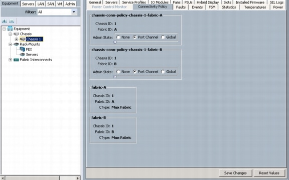
Chassis Discovery Policy
These steps provide details for modifying the chassis discovery policy as the base architecture includes two uplinks from each fabric extender installed in the Cisco UCS chassis.
1.
2.
3.
4.
5.
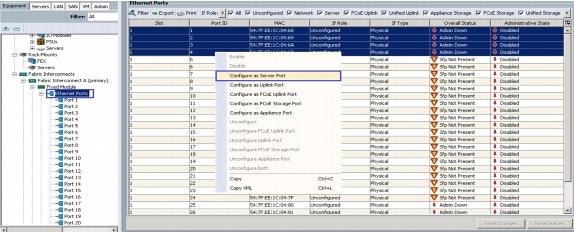
Enable Server and Uplink Ports
These steps provide details for enabling Fibre Channel, server and uplinks ports.
1.
2.
3.
4.
5.
6.
7.
8.
9.
10.
11.
12.
13.
14.
15.
16.
17.
18.
19.
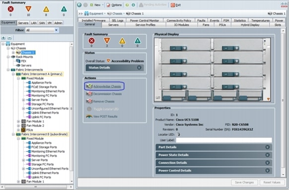
Acknowledge the Cisco UCS Chassis
The connected chassis needs to be acknowledged before it can be managed by Cisco UCS Manager.
1.
2.
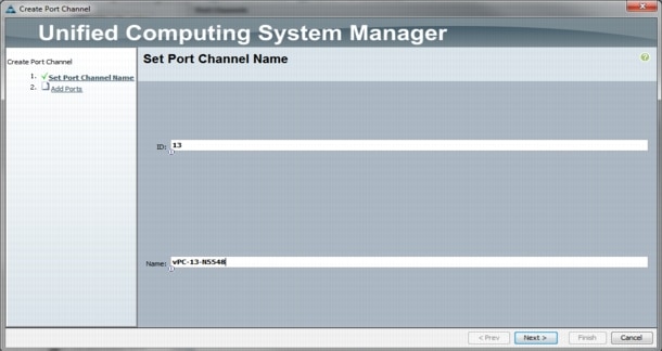
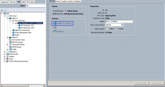
Create Uplink Port Channels to the Cisco Nexus 5548 Switches
These steps provide details for configuring the necessary Port Channels out of the Cisco UCS environment.
1.
Note
2.
3.
4.
5.
6.
7.
8.
9.
10.
11.
12.
13.
14.
15.
16.
17.
18.
19.
20.
21.
22.
23.
24.
25.
26.
27.
28.
29.
30.
31.
Create an Organization
These steps provide details for configuring an organization in the Cisco UCS environment. Organizations are used as a means to organize and restrict access to various groups within the IT organization, thereby enabling multi-tenancy of the compute resources. This document does not assume the use of Organizations, however the necessary steps are included below.
1.
2.
3.
4.
5.
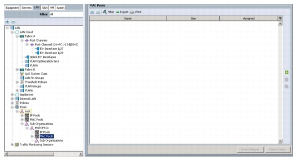
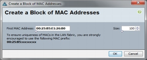
Create a MAC Address Pool
These steps provide details for configuring the necessary MAC address pool for the Cisco UCS environment.
1.
2.
3.
4.
5.
6.
7.
8.
9.
10.
11.
12.
13.
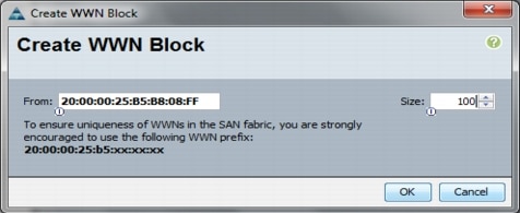
Create WWNN Pools
These steps provide details for configuring the necessary WWNN pools for the Cisco UCS environment.
1.
2.
3.
4.
5.
6.
7.
8.
Note
9.
10.
11.
12.
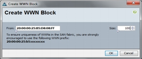
Create WWPN Pools
These steps provide details for configuring the necessary WWPN pools for the Cisco UCS environment.
1.
2.
3.
4.
5.
6.
7.
8.
9.
10.
11.
12.
13.
14.
15.
16.
17.
18.
19.
20.
21.
22.
23.
24.
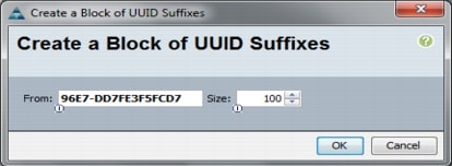
Create UUID Suffix Pools
These steps provide details for configuring the necessary UUID suffix pools for the Cisco UCS environment.
1.
2.
3.
4.
5.
6.
7.
8.
9.
10.
11.
12.
13.
Create Server Pools
These steps provide details for configuring the necessary UUID suffix pools for the Cisco UCS environment.
1.
2.
3.
4.
5.
6.
7.
8.
9.
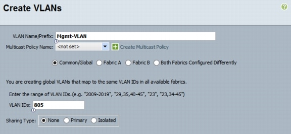
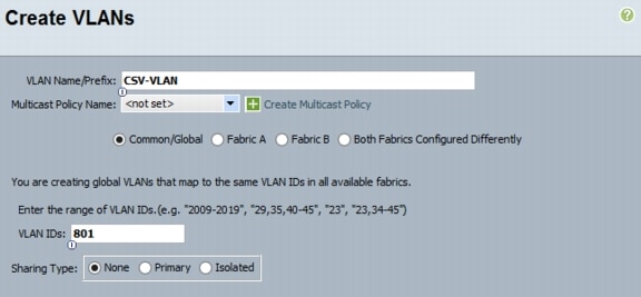
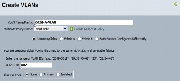
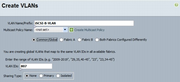
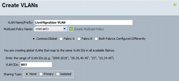
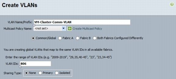
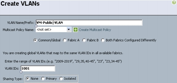
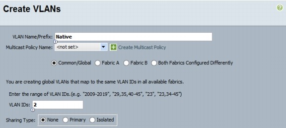
Create VLANs
These steps provide details for configuring the necessary VLANs for the Cisco UCS environment.
1.
Note
2.
3.
4.
5.
6.
7.
8.
9.
10.
11.
12.
13.
14.
15.
16.
17.
18.
19.
20.
21.
22.
23.
24.
25.
26.
27.
28.
29.
30.
31.
32.
33.
34.
35.
36.
37.
38.
39.
40.
41.
42.
43.
44.
45.
46.
47.
48.
49.
50.
51.
52.
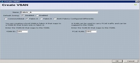
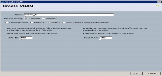
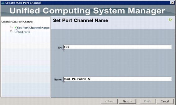
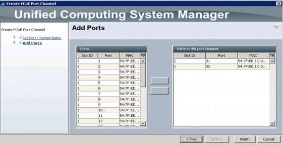
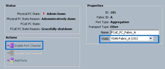
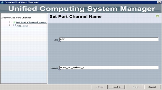
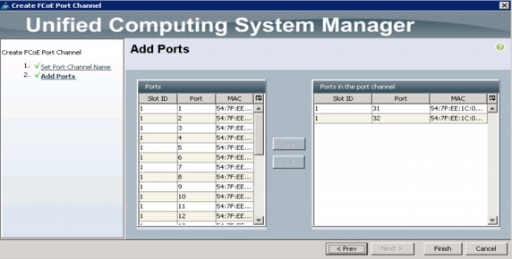
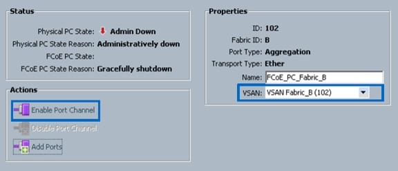
Create VSANs and FCoE Port Channels
These steps provide details for configuring the necessary VSANs and FCoE Port Channels for the Cisco UCS environment.
1.
2.
3.
4.
5.
6.
7.
8.
9.
10.
11.
12.
13.
14.
15.
16.
17.
18.
19.
20.
21.
22.
23.
24.
25.
26.
27.
28.
29.
30.
31.
32.
Note
If the Overall State results in an error condition and does not clear after 30 seconds the FC uplink ports on the Nexus 5548UP will need to shut down and brought back up in order to establish the link.
33.
34.
35.
36.
37.
38.
39.
40.
41.
42.
43.
44.
45.
46.
Note
•
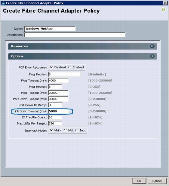
Create a FC Adapter Policy for NetApp Storage Arrays
These steps provide details for a FC adapter policy for NetApp storage arrays.
1.
2.
3.
4.
5.
6.
7.
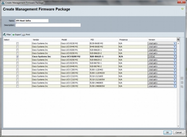
Create a Firmware Management Package
These steps provide details for a firmware management policy for n the Cisco UCS environment.
1.
2.
3.
4.
5.
6.
7.
8.
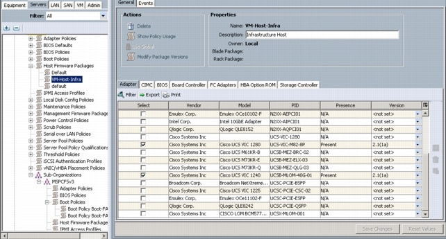
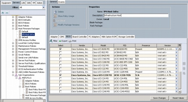
Create Firmware Package Policy
These steps provide details for creating a firmware management policy for a given server configuration in the Cisco UCS environment. Firmware management policies allow the administrator to select the corresponding packages for a given server configuration. These often include adapter, BIOS, board controller, FC adapters, HBA option ROM, and storage controller properties.
1.
2.
3.
4.
5.
6.
7.
8.

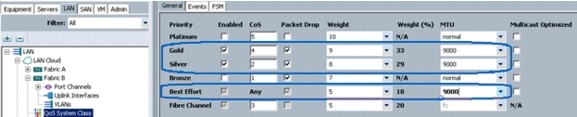
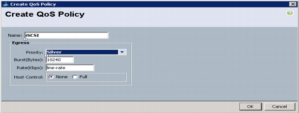
Set Jumbo Frames and Enable Quality of Service in Cisco UCS Fabric
These steps provide details for setting Jumbo frames and enabling the quality of server in the Cisco UCS Fabric.
1.
2.
3.
4.
5.
6.
7.
8.
9.
10.
11.
12.
13.
14.
15.
16.
17.
18.
19.
20.
21.
22.
23.
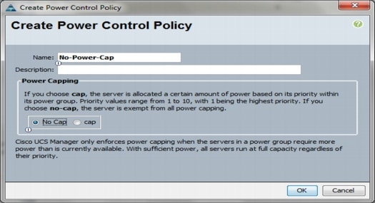
Create a Power Control Policy
These steps provide details for creating a Power Control Policy for the Cisco UCS environment.
1.
2.
3.
4.
5.
6.
7.
8.
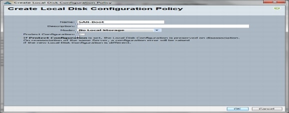
Create a Local Disk Configuration Policy
These steps provide details for creating a local disk configuration for the Cisco UCS environment, which is necessary if the servers in question do not have a local disk.
Note
1.
2.
3.
4.
5.
6.
7.
8.
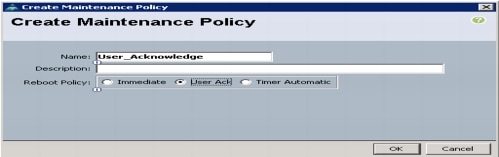
Create a Maintenance Policy
These steps provide details for creating a maintenance policy. The maintenance policy controls the timing of a server reboot after an update has been made that requires the server to reboot prior to the update taking affect.
1.
2.
3.
4.
5.
6.
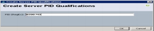
Create a Server Pool Qualification Policy
These steps provide details for creating a server pool qualification policy for the Cisco UCS environment.
1.
2.
3.
4.
5.
6.
7.
8.
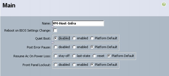
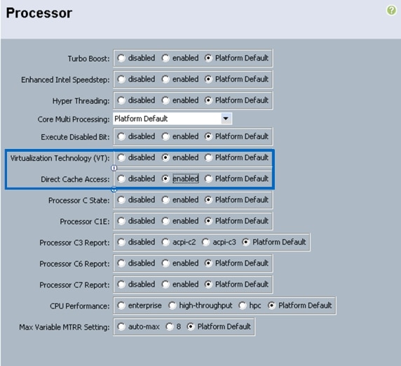
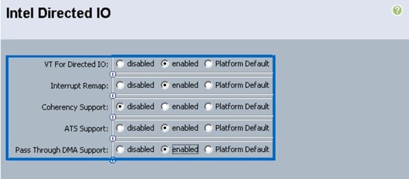
Create a Server BIOS Policy
These steps provide details for creating a server BIOS policy for the Cisco UCS environment.
1.
2.
3.
4.
5.
6.
7.
8.
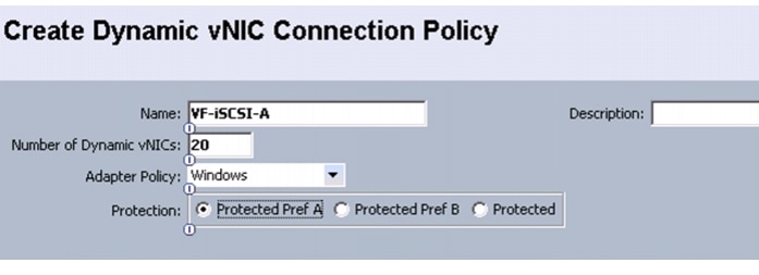
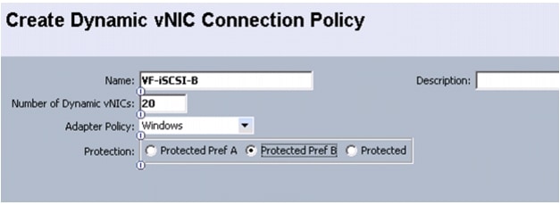
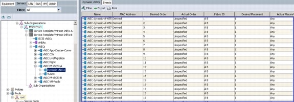
Create Dynamic vNIC Connection Policy for VM-FEX (SR-IOV)
These steps provide details for creating the vNIC Connection Policy for use with VM-FEX (SR-IOV).
1.
2.
3.
4.
5.
Note
6.
7.
8.
9.
10.
11.
Note
12.
13.
14.
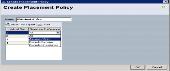
Create vNIC/HBA Placement Policy for Virtual Machine Infrastructure Hosts
1.
2.
3.
4.
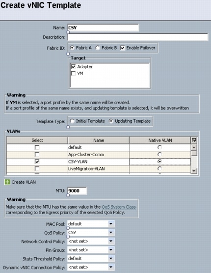
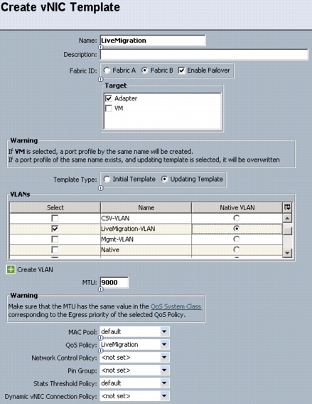
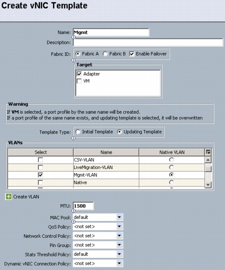
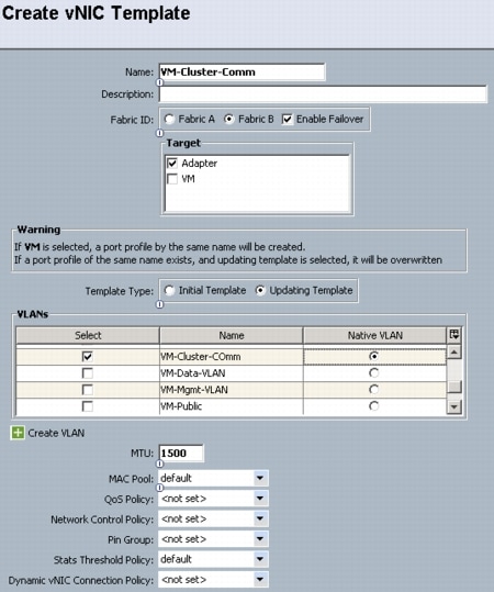
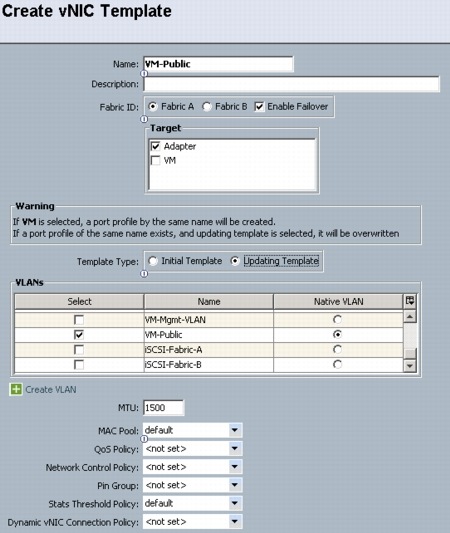
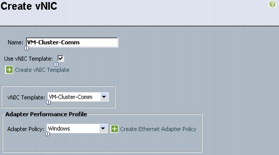
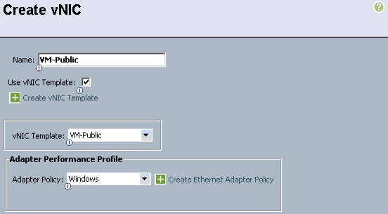
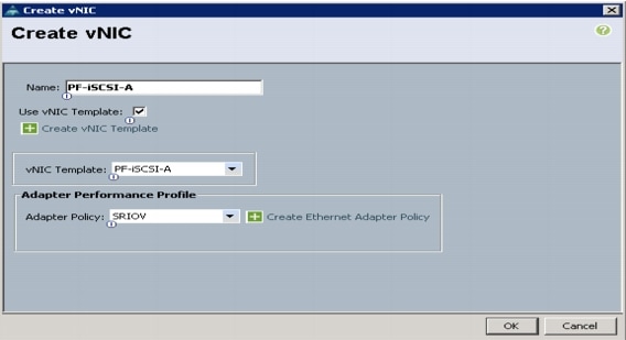
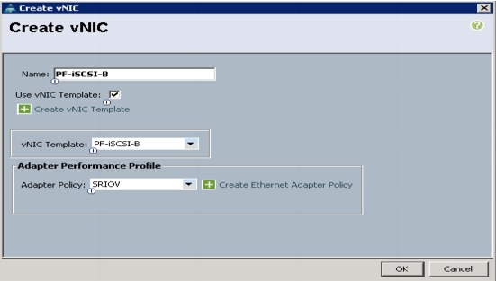
Create a vNIC Template
These steps provide details for creating multiple vNIC templates for the Cisco UCS environment.
1.
2.
3.
4.
5.
6.
7.
8.
9.
10.
11.
12.
13.
14.
15.
16.
17.
18.
19.
20.
21.
22.
23.
24.
25.
26.
27.
28.
29.
30.
31.
32.
33.
34.
35.
36.
37.
38.
39.
40.
41.
42.
43.
44.
45.
46.
47.
48.
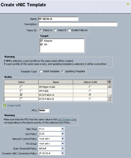
Note
49.
50.
51.
52.
53.
54.
55.
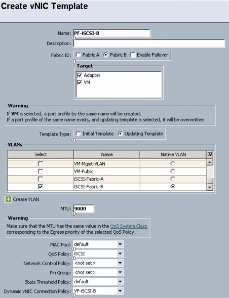
Note
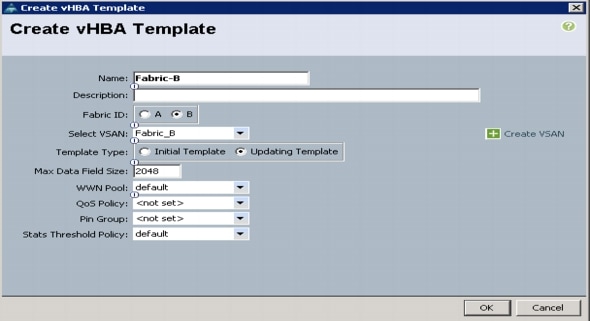
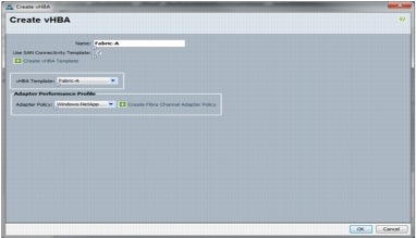
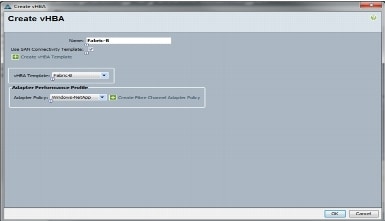
Create vHBA Templates for Fabric A and B
These steps provide details for creating multiple vHBA templates for the Cisco UCS environment.
1.
2.
3.
4.
5.
6.
7.
8.

9.
10.
11.
12.
13.
14.
15.
16.
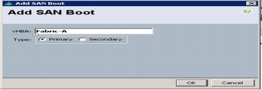
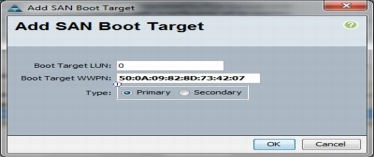
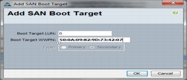
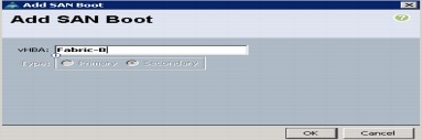
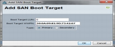
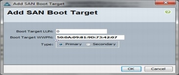
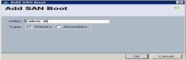
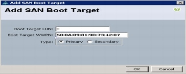
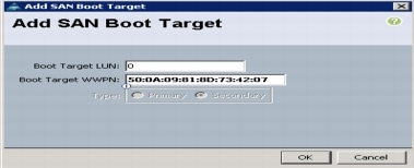
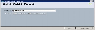
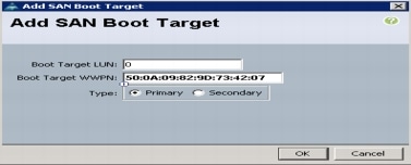
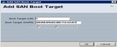
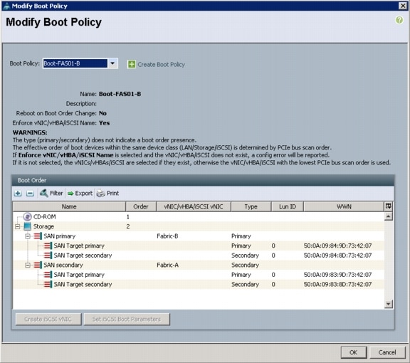
Create Boot Policies
These steps provide details for creating boot policies for the Cisco UCS environment. These directions apply to an environment in which each storage Controller Ba port is connected to fabric A and each storage Controller Bb port is connected to fabric B. In these steps, 2 boot policies will be configured. The first policy will configure the primary target to be controller A port 2a and the second boot policy primary target will be controller B port 2b.
1.
2.
3.
4.
5.
6.
7.
8.
9.
10.
11.
12.
13.
14.
15.
16.
17.
18.
19.
20.
21.
22.
23.
24.
25.
26.
27.
28.
29.
30.
31.
32.
33.
34.
35.
36.
37.
38.
39.
40.
41.
42.
43.
44.
45.
46.
47.
48.
49.
50.
51.
52.
53.
54.
55.
56.
57.
58.
59.
60.
61.
62.
63.
64.
65.
66.
67.
68.
69.
Create Service Profile Templates
This section details the creation of two service profile templates: one for fabric A and one for fabric B. The first profile is created and then cloned and modified for the second host.
1.
2.
3.
4.
5.
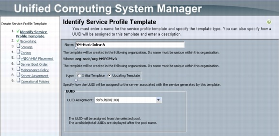
Identify the Service Profile Template
These steps detail configuration info for the Identify the Service Profile Template Section.
1.
2.
3.
4.
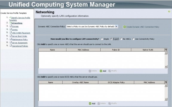
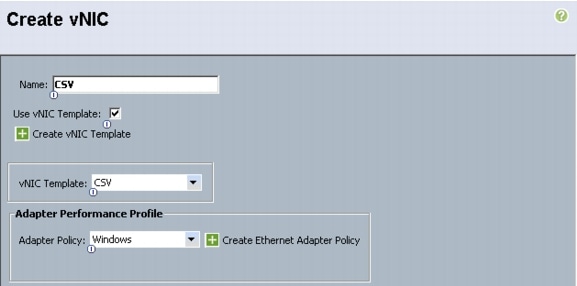
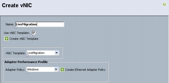
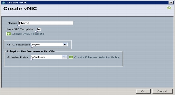
Networking Section
Leave the Dynamic vNIC Connection Policy field at the default.
1.
2.
3.
4.
5.
6.
7.
8.
9.
10.
11.
12.
13.
14.
15.
16.
17.
18.
19.
20.
21.
22.
23.
24.
25.
26.
27.
28.
29.
30.
31.
32.
33.
34.
35.
36.
37.
38.
39.
40.
41.
42.
43.
44.
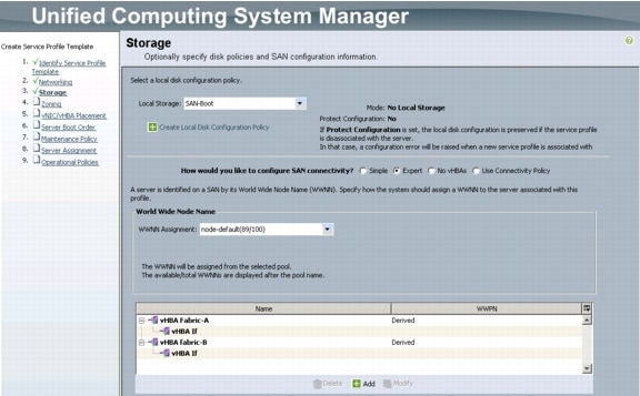
Storage Section
1.
2.
3.
4.
5.
6.
7.
8.
9.
10.
11.
12.
13.
14.
15.
16.
17.
18.
19.
Zoning Section
Note
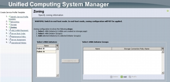
1.
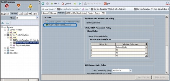
vNIC/vHBA Placement Section
Select the VM-Host-Infra Placement Policy in the Select Placement field.
1.
–
–
–
–
–
–
–
2.
–
–
3.
4.
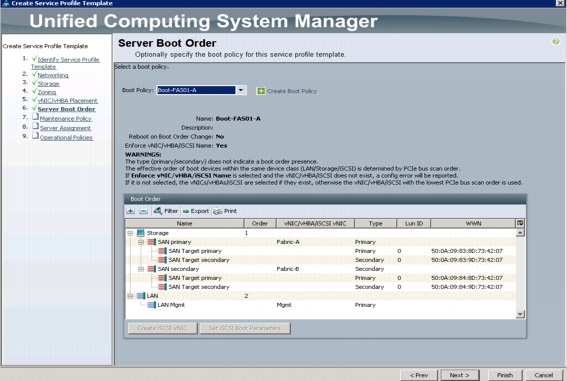
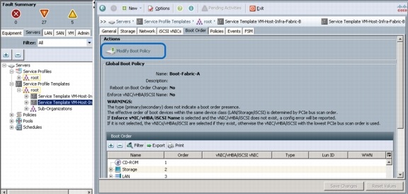
Server Boot Order Section
1.
2.
3.
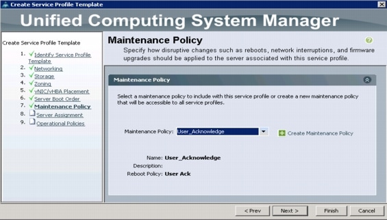
Maintenance Policy Section
1.
2.
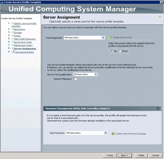
Server Assignment Section
1.
2.
3.
4.
5.
Operational Policies Section
1.
2.
3.
4.
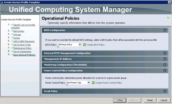
5.
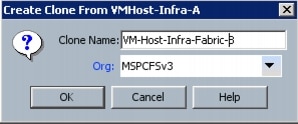
Create the Fabric-B Template.
1.
2.
3.
4.
5.
6.
7.
8.
9.
10.

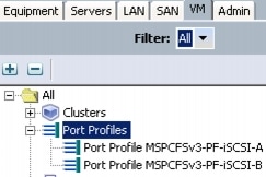
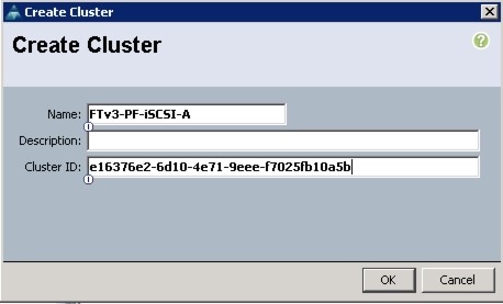
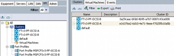
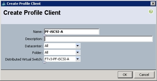
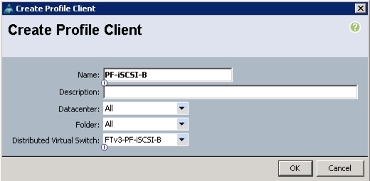
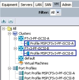
Create VM-FEX Port Profiles and Virtual Switch Clusters
These steps provide details for verifying that the port profiles and creating virtual Switch Clusters which will be used by the SR-IOV physical and virtual functions.
1.
2.
3.
4.
5.
[system.guid]::NewGuid()6.
7.
8.
9.
10.
11.
12.
13.
14.
15.
16.
17.
18.
19.
20.
21.
22.
23.
24.
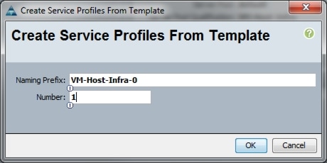
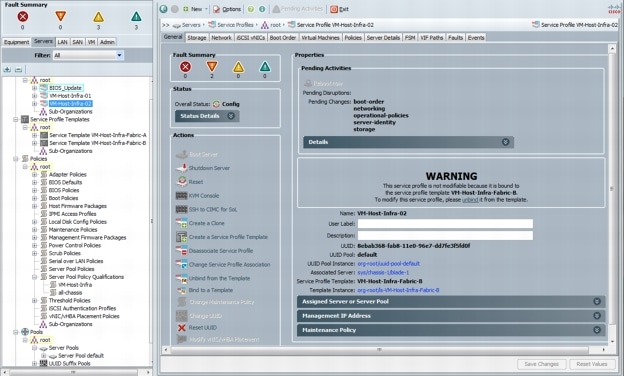
Create Service Profiles
These steps provide details for creating a service profile from a template.
1.
2.
3.
4.
5.
6.
7.
8.
9.
10.
11.
12.

13.
14.
15.
16.
17.
Add More Server Blades to the FlexPod Unit
Add server pools, service profile templates, and service profiles in the respective organizations to add more servers to the FlexPod unit. All other pools and policies are at the root level and can be shared among the organizations.
Gather Necessary Information
After the Cisco UCS service profiles have been created (in the previous steps), the infrastructure blades in the environment each have a unique configuration. To proceed with the FlexPod deployment, specific information must be gathered from each Cisco UCS blade and from the NetApp controllers. Insert the required information in the tables below.
Table 10 FC Port Names for Storage Controllers 1 and 2.
Table 11 vHBA WWPNs for Fabric A and Fabric B.
Note
SAN Configuration
Create Device Aliases
These steps provide details for configuring device aliases and zones for the primary boot path. Instructions are given for all target ports, however, the redundant path is enabled following operating system installation.
Nexus 5548 A
1.
2.
3.
4.
5.
6.
7.
8.
9.
10.
11.
Nexus 5548 B
1.
2.
3.
4.
5.
6.
7.
8.
9.
10.
Create Zones for Each Service Profile (Part 1)
Note
Nexus 5548 A
Create the Zones and Add Members
1.
2.
3.
4.
5.
6.
7.
8.
Create the Zoneset and Add the Necessary Members
1.
2.
3.
4.
Activate the Zoneset
1.
2.
3.
Nexus 5548 B
Create the Zones and Add Members
1.
2.
3.
4.
5.
6.
7.
8.
Create the Zoneset and Add the Necessary Members
1.
2.
3.
4.
Activate the Zoneset
1.
2.
3.
NetApp FAS3240A Deployment Procedure - Part 2
The following sections provide detailed procedures for configuring the interface groups (or igroups), creating LUNs for the service profiles on the storage controllers, and mapping those LUNs to the igroups to be accessible to the service profiles.
Create iGroups
The following steps provide details for configuring the necessary igroups on the storage controller the enable the mapping of a given host to the storage resources.
Controller A
For the odd service profile to boot off of controller A, execute the following to create igroups for each vHBA:
igroup create -f -t hyper_v VM-Host-Infra-01 <vHBA_A WWPN> <vHBA_B WWPN>.igroup create -f -t hyper_v VM-Host-Infra-03 <vHBA_A WWPN> <vHBA_B WWPN>.Controller B
For the even service profile to boot off of controller B, execute the following to create igroups for each vHBA:
igroup create -f -t hyper_v VM-Host-Infra-02 <vHBA_A WWPN> <vHBA_B WWPN>.igroup create -f -t hyper_v VM-Host-Infra-04 <vHBA_A WWPN> <vHBA_B WWPN>.Create LUNs
This section provides detailed procedure for configuring the necessary LUNs on the storage controller for deployment of the SAN booted windows operating system.
Controller A
For the odd service profile to boot off of controller A, execute the following to create the LUN for each OS installation:
lun create -s 150g -t hyper_v -o noreserve /vol/ucs_boot/VM-Host-Infra-01.lunlun create -s 150g -t hyper_v -o noreserve /vol/ucs_boot/VM-Host-Infra-03.lunController B
For the even service profile to boot off of controller B, execute the following to create the LUN for each OS installation:
lun create -s 150g -t hyper_v -o noreserve /vol/ucs_boot/VM-Host-Infra-02.lunlun create -s 150g -t hyper_v -o noreserve /vol/ucs_boot/VM-Host-Infra-04.lunMap LUNs to iGroup
For mapping the necessary LUNs on the storage controller to the created iGroups, execute these commands on controller A and Controller B.
Controller A
For the odd service profile to boot off of controller A map the LUN for the OS installation:
lun map /vol/ucs_boot/VM-Host-Infra-01.lun VM-Host-Infra-01lun map /vol/ucs_boot/VM-Host-Infra-03.lun VM-Host-Infra-03Controller B
For the even service profile to boot off of controller B map the LUN for the OS installation:
lun map /vol/ucs_boot/VM-Host-Infra-02.lun VM-Host-Infra-02lun map /vol/ucs_boot/VM-Host-Infra-04.lun VM-Host-Infra-04Microsoft Windows Server 2012 Hyper-V Deployment Procedure
Setup the Windows Server 2012 install
This section details the steps required to prepare the server for OS installation.
The following steps describe adding and mapping ISO image for installing OS:
All Hosts
1.
2.
3.
4.
5.
6.
7.
Install Windows Server 2012
The following steps describe the installation of Windows Server 2012 to each hosts:
All Hosts
1.
2.
3.
4.
5.
Note
6.
7.
8.
9.
10.
11.
12.
13.
14.
15.
Note
•
•
16.
17.
18.
19.
20.
21.
22.
Install Windows Roles and features
This section provides detailed information on installing all the required roles and features from Windows Server 2012 Installation media. If you have unmapped the installation ISO you will need to remap it now.
All Hosts
1.
2.
3.
4.
Add-WindowsFeature -Name NET-Framework-Core -Source E:\sources\sxs5.
Add-WindowsFeature Hyper-V, Failover-Clustering, Multipath-IO,
Data-Center-Bridging -IncludeManagementTools -Restart
Install Windows eNIC Drivers
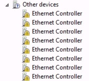
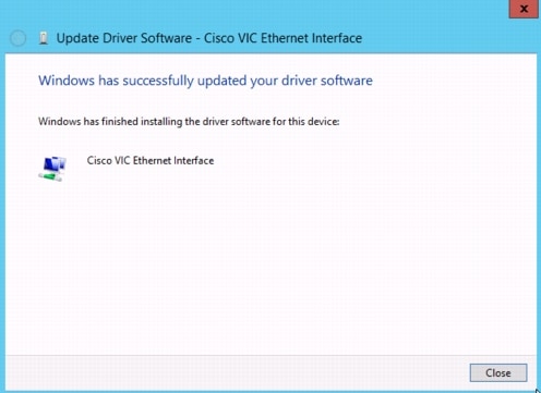
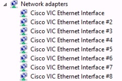
This section provides detailed information on installing all the required network drivers.
All Hosts
1.
2.
3.
4.
5.
6.
7.
8.
9.
10.
11.
12.
13.
Note
14.
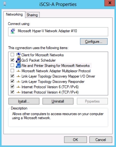
Configure Windows Networking for FlexPod
This section provides detailed information on renaming the network for each Hyper-V host.
All Hosts
1.
2.
3.
4.
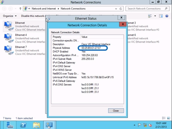
Note
Gwmi Win32_NetworkAdapter | Where{$_.MACaddress -ne $Null} | FT NetConnectionID,
MACaddress
5.

6.
7.
8.
Note
9.
10.
11.
12.
–
–
–
–
–
–
–
13.
14.
15.

Install NetApp MPIO DSM
This section provides information on installing the NetApp Device Specific Module (DSM). For more information on NetApp DSM installation, see:
https://library.netapp.com/ecm/ecm_get_file/ECMP1141002
All Hosts
1.
http://support.netapp.com/NOW/download/software/mpio_win/4.0/ntap_win_mpio_4.0_setup_x64.msi
2.
3.
4.
5.
6.
7.
8.
9.
10.
11.
Create Zones for Each Service Profile (Part 2)
The following section describes how to zone in the redundant fabric paths.
Nexus 5548 A
Create the Zones and Add Members
1.
2.
3.
4.
5.
6.
7.
8.
9.
10.
11.
12.
13.
14.
15.
16.
Add the Necessary Members to the Zoneset
1.
2.
3.
4.
Activate the Zoneset
1.
2.
3.
Nexus 5548 B
Create the Zones and Add Members
1.
2.
3.
4.
5.
6.
7.
8.
9.
10.
11.
12.
13.
14.
15.
16.
Create the Zoneset and Add the Necessary Members
1.
2.
3.
4.
Activate the Zoneset
1.
2.
3.
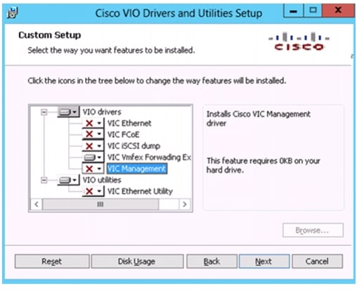
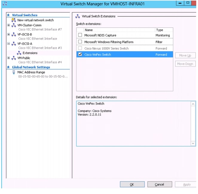
Install Cisco Virtual Switch Forwarding Extensions for Hyper-V
Cisco Virtual Switch Forwarding Extensions for Hyper-V enable SR-IOV capability when using VM-FEX for Hyper-V. The installation package is located in the Cisco UCS Manager drivers ISO image starting with version 2.1. The installation package file name is CSCO_VIO_INSTALLER_64_2.x.x.msi. It is located in the Windows\installers\Cisco\MLOM\W2K12\x64 directory.
All Hosts
1.
2.
3.
4.
5.
–
–
–
–
–
Note
6.
7.
8.
Create Hyper-V Virtual Network Switches
All Hosts
1.
2.
3.
New-vmswitch -name VM-Public -NetAdapterName VM-Public -AllowManagementOS $false4.
New-vmswitch -name VM-Cluster-Comm -NetAdapterName VM-Cluster-Comm -AllowManagementOS $false
5.
New-vmswitch -name VF-iSCSI-A -NetAdapterName PF-iSCSI-A -AllowManagementOS $false -EnableIov $true
6.
New-vmswitch -name VF-iSCSI-B -NetAdapterName PF-iSCSI-B -AllowManagementOS $false -EnableIov $true
7.
8.
9.
10.
11.
12.
13.
Domain Controller Virtual Machines
Most environments will already have an active directory infrastructure and will not require additional domain controllers to be deployed for Flexpod with Microsoft Windows Server 2012 Hyper-V. The optional domain controllers can be omitted from the configuration in this case or used as a resource domain. The domain controller virtual machines will not be clustered because of the redundancy provided by deploying multiple domain controllers running in virtual machines on different servers. Since these virtual machines reside on Hyper-V hosts that run Windows Failover cluster, but are not clustered themselves, Hyper-V Manager should be used to manage them instead of Virtual Machine Manager.
Prepare Nodes for Clustering
This section provides details on preparing each node to be added to the Hyper-V cluster.
All Hosts
1.
Rename-Computer -NewName <hostname> -restart2.
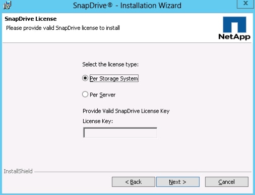
Add-Computer -DomainName <domain_name> -RestartInstall NetApp SnapDrive
This section provides detailed information on installing NetApp SnapDrive Windows. For more information on NetApp SnapDrive Windows installation see:
https://library.netapp.com/ecm/ecm_get_file/ECMP1141002
Service Account preparation
1.
Note
2.
All Hosts
1.
http://support.netapp.com/NOW/download/software/snapdrive_win/6.5/SnapDrive6.5_x64.exe
2.
3.
4.
5.
6.
7.
8.
9.
10.
11.
12.
13.
Note
14.
sdcli preferredIP set -f <<var_controller1>> -IP <<var_controller1_e0m_ip>>
sdcli preferredIP set -f <<var_controller2>> -IP <<var_controller2_e0m_ip>>
15.
sdcli transport_protocol set -f <<var_controller1>> -type https -user root -pwd
<<var_admin_passwd>>
sdcli transport_protocol set -f <<var_controller2>> -type https -user root -pwd <<var_admin_passwd>>Install NetApp SnapManager for Hyper-V
This section provides detailed information on installing NetApp SnapManger for Hyper-V. For more information on NetApp SnapManger for Hyper-V installation, see:
https://library.netapp.com/ecm/ecm_get_file/ECMP1141002
Service Account Preparation
1.
Note
2.
All Hosts
1.
http://support.netapp.com/NOW/download/software/snapmanager_hyperv_win/1.2/SMHV1.2_NetApp_x64.exe
2.
3.
4.
5.
6.
7.
8.
9.
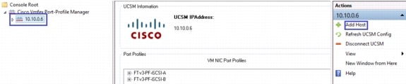
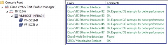
Install VM-FEX Port Profile Management Utilities in Hyper-V
All Hosts
1.
2.
3.
4.
5.
6.
7.
Create a Cluster
One Server Only
1.
2.
New-Cluster -Name <cluster_name> -Node <Node1>, <Node2>, <node3>, <node4>
-NoStorage -StaticAddress <cluster_ip_address>
3.
Get-ClusterNetworkInterface | ? Name -like *CSV* | Group Network| %{
(Get-ClusterNetwork $_.Name).Name = 'CSV'}
Get-ClusterNetworkInterface | ? Name -like *LiveMigration* | Group Network| %{ (Get-ClusterNetwork $_.Name).Name = 'LM'}Get-ClusterNetworkInterface | ? Name -like *Mgmt* | Group Network| %{ (Get-ClusterNetwork $_.Name).Name = 'Mgmt'}4.
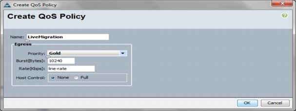
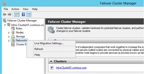
(Get-ClusterNetwork -Name CSV).Metric = 900Configure Live Migration network.
One Server Only
1.
2.
3.
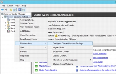
Change the Cluster to Use a Quorum Disk.
One Server Only
1.
Move-ClusterGroup "Available Storage" -Node $env:COMPUTERNAME | Start-ClusterGroup2.
3.
4.
5.
6.
7.
8.
9.
10.
11.
12.
13.
14.
15.
16.
17.
18.
19.
20.
21.
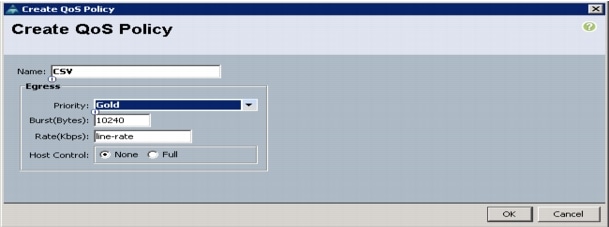
Create CSV LUN for VM Storage
One Server Only
1.
Move-ClusterGroup "Available Storage" -Node $env:COMPUTERNAME | Start-ClusterGroup2.
3.
4.
5.
6.
7.
8.
9.
10.
11.
12.
13.
14.
15.
Validated the Cluster
Run the cluster validation wizard to verify that the cluster is operating correctly.
1.
2.
3.
4.
Deploying a Virtual Machine with VM-FEX
Create Virtual Machines
Now the Windows Failover Cluster created and configured highly available virtual machines can be added to the cluster.
1.
2.
3.
4.
5.
6.
7.
8.
9.
10.
11.
12.
13.
14.
15.
16.
17.
18.
19.
20.
21.
22.
23.
24.
25.
26.
27.
28.
29.
30.
31.
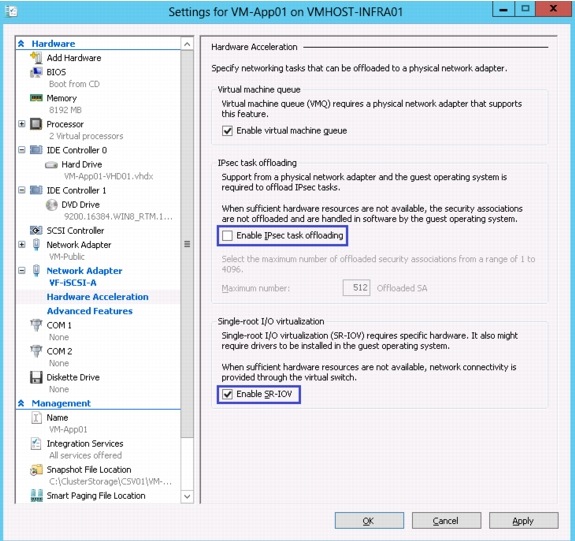
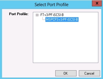
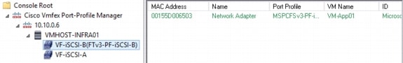
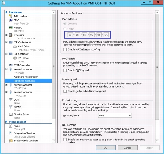
Attach Port Profile to the Virtual Machine
1.
2.
3.
4.
5.
6.
7.
8.
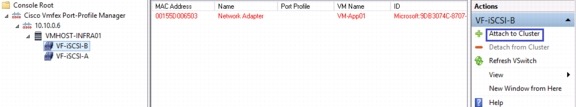
9.
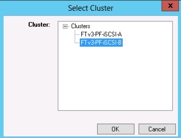
10.
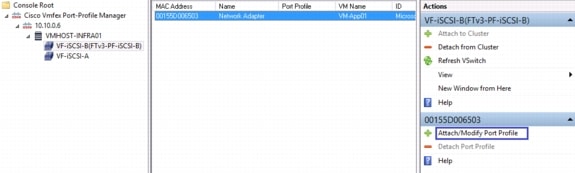
11.
12.
13.
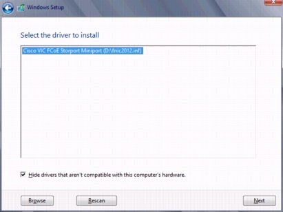
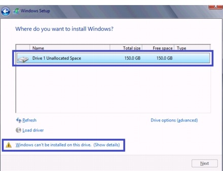
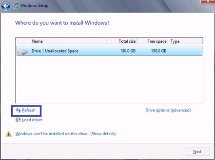
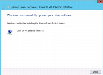
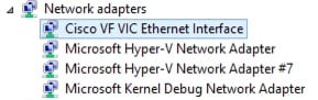
Install Windows and Cisco VF VIC Driver
1.
2.
3.
4.
5.
6.
7.
8.
9.
10.
11.
12.
13.
14.
15.
16.
•
•
17.
Install Windows Features in the Virtual Machine
1.
2.
3.
4.
Add-WindowsFeature -Name NET-Framework-Core -Source D:\sources\sxs5.
Add-WindowsFeature Multipath-IO -IncludeManagementTools -RestartConfigure Windows Host iSCSI initiator
The following steps describe how to configure the built in Microsoft iSCSI initiator.
All Hosts
1.
2.
Set-Service -Name MSiSCSI -StartupType Automatic3.
Start-Service -Name MSiSCSI4.
Enable-MSDSMAutomaticClaim -BusType iSCSI5.
Set-MSDSMGlobalDefaultLoadBalancePolicy -Policy RR6.
New-IscsiTargetPortal -TargetPortalAddress <<var_controller1_iscsia_ip>>
-InitiatorPortalAddress <iscsia_ipaddress>
New-IscsiTargetPortal -TargetPortalAddress <<var_controller2_iscsia_ip>> -InitiatorPortalAddress <iscsia_ipaddress>7.
Get-IscsiTarget | Connect-IscsiTarget -IsPersistent $true -IsMultipathEnabled
$true -InitiatorPo rtalAddress <iscsia_ipaddress>
Get-IscsiTarget | Connect-IscsiTarget -IsPersistent $true -IsMultipathEnabled $true -InitiatorPo rtalAddress <iscsib_ipaddress>Install NetApp Utilities in the Virtual Machine
1.
2.
Create and Map iSCSI LUNs using SnapDrive
1.
2.
3.
4.
5.
6.
7.
8.
9.
10.
11.
Appendix A
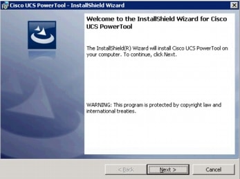
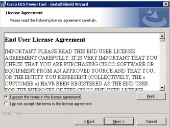
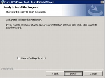
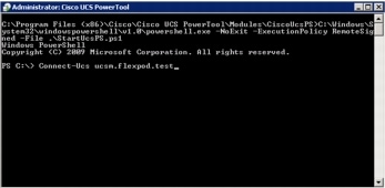
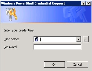
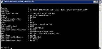
Installing Cisco UCS PowerTool
The Cisco UCS PowerTool should be installed on the FlexPod Management server.
Download the Cisco UCS PowerTool version 0.9.9.0 or newer from the Cisco Developer Network. It can be found in the Microsoft Management section:
http://developer.cisco.com/web/unifiedcomputing/microsoft
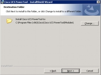
Extract the zip file and execute the extracted exe file.
1.
2.
Appendix B: Installing the DataONTAP PowerShell Toolkit
1.
https://communities.netapp.com/community/products_and_solutions/microsoft/powershell2.
3.
4.
5.
6.
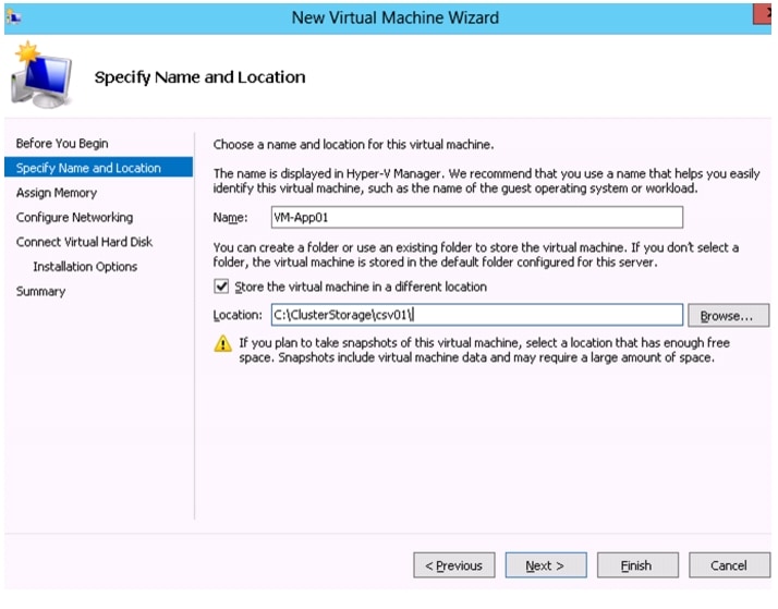
Appendix C: Creating Domain Controller Virtual Machine (Optional)
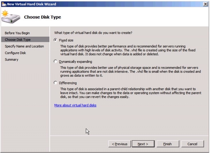
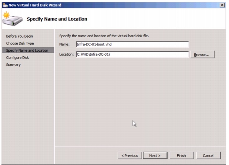
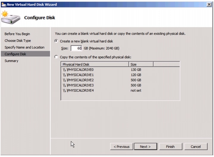
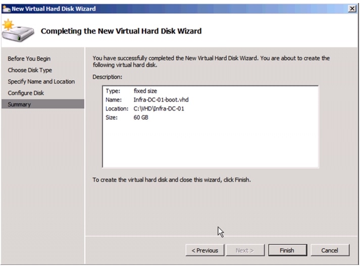
Create VHD for Domain Controller Virtual Machine.
Create the following VHD storage resources that will be used by the virtual machines running active directory domain controller roles:
1.
2.
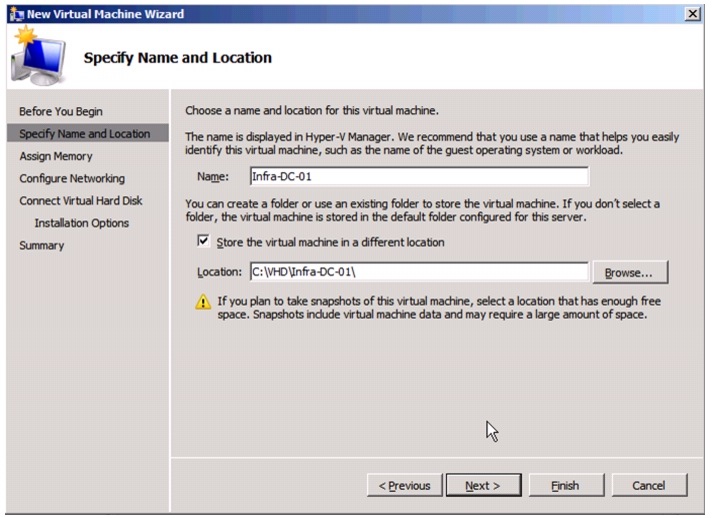
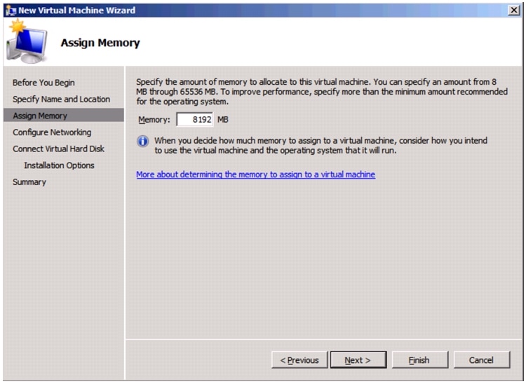
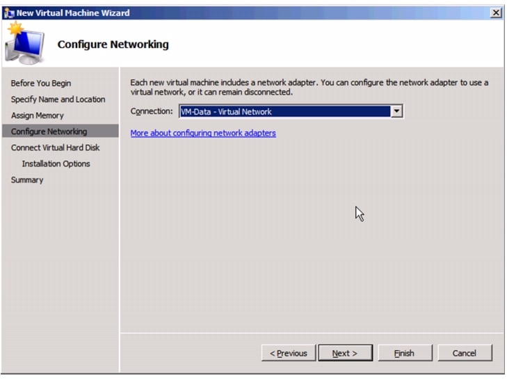
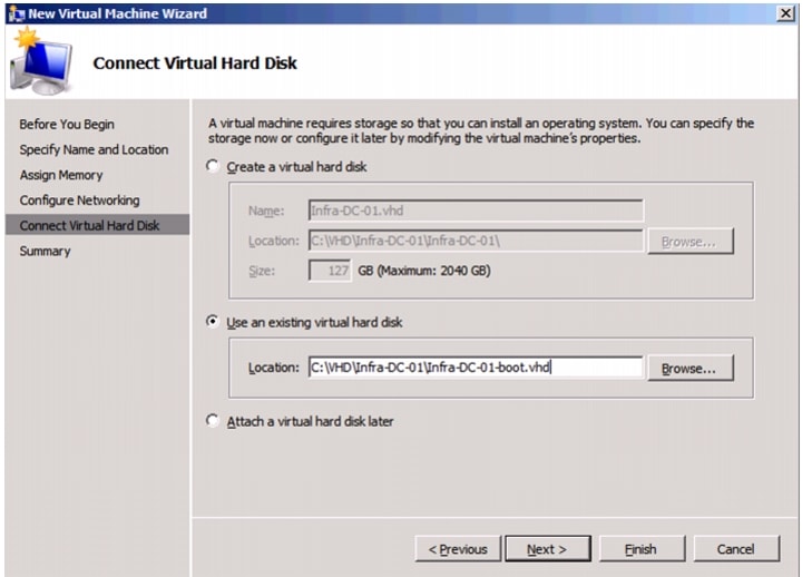
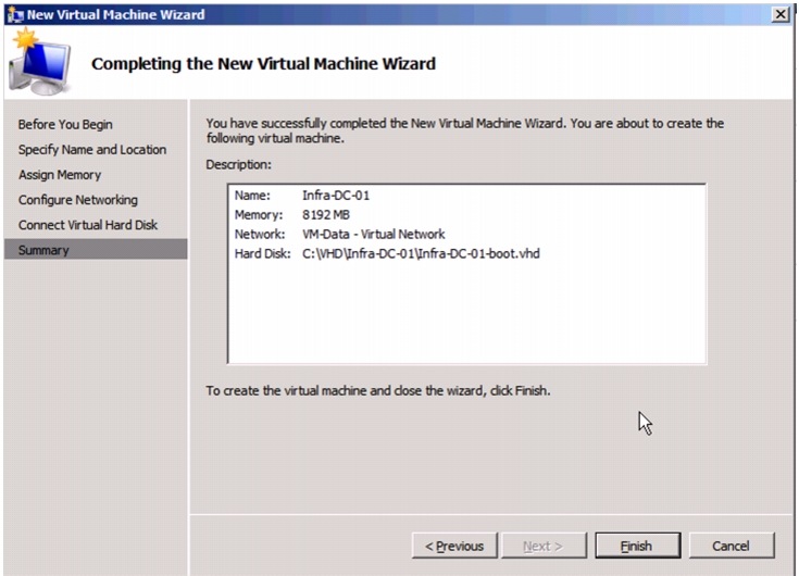
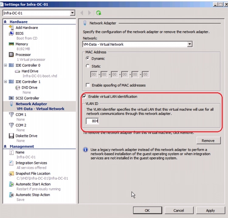
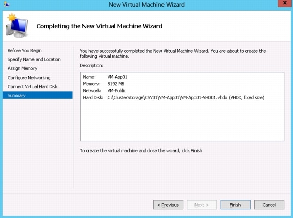
Create the following virtual machines that will be used by the active directory domain controller roles.
1.
2.
3.
4.
5.
6.
7.
8.
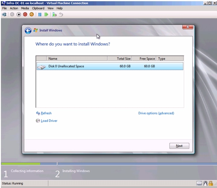
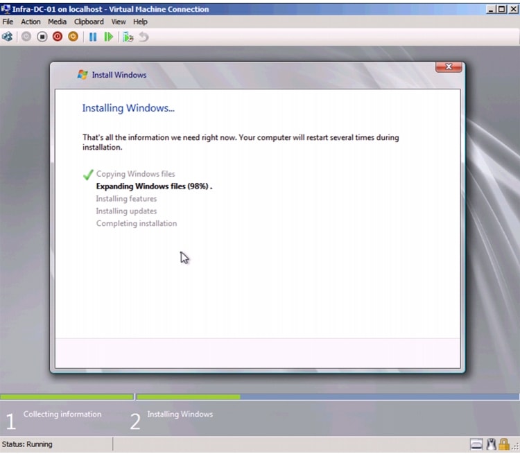
Install Windows in a Domain Controller Virtual Machine
Follow the screenshots to install windows in a Domain Controller VM.
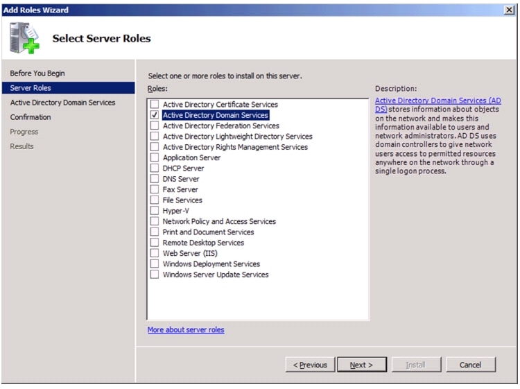
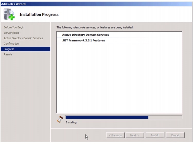
Install Active Directory Services
Follow the screenshots to install windows in a Domain Controller VM.
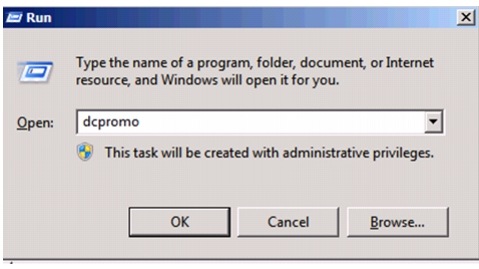
Run dcpromo to configure the Domain Controller.
Complete the domain controller installation and repeat the process on VM-Host-Infra-02 to install the redundant domain controller.