Table Of Contents
About Cisco Validated Design (CVD) Program
Cisco UCS Common Platform Architecture Version2 (CPA v2) for Big Data with Pivotal HD and HAWQ
Cisco UCS Common Platform Architecture for Big Data
Server Configuration and Cabling
Software Distributions and Versions
Performing Initial Setup of Cisco UCS 6296 Fabric Interconnects
Configure Fabric Interconnect A
Configure Fabric Interconnect B
Logging Into Cisco UCS Manager
Upgrading UCSM Software to Version 2.2(1b)
Adding Block of IP Addresses for KVM Access
Editing the Chassis/FEX Discovery Policy
Enabling the Server Ports and Uplink Ports
Creating Pools for Service Profile Templates
Creating Policies for Service Profile Templates
Creating a Host Firmware Package Policy
Creating the Best Effort Policy
Creating a Local Disk Configuration Policy
Creating a Service Profile Template
Configuring Network Settings for the Template
Configuring a Storage Policy for the Template
Configuring a vNIC/vHBA Placement for the Template
Configuring a Server Boot Order for the Template
Configuring Server Assignment for the Template
Configuring Operational Policies for the Template
Configuring Disk Drives for Operating System on NameNodes
Configuring Disk Drives for Operating System on DataNodes
Installing Red Hat Linux 6.4 with KVM
Setting Up Password-less Login
Installing and Configuring Parallel SSH
Configuring /etc/hosts and DNS
Creating RedHat Local Repository
Download Java SE 7 Development Kit (JDK)
Configuring Data Drives on Data Nodes
Configuring the Filesystem for DataNodes
Installing Pivotal HD Using Pivotal Command Center
Launching Pivotal Command Center
Configuring and Deploying a Cluster
Configuration Directives for PHD Services
Cluster Services - Global Configuration Variables (Cluster Config.xml)
Pivotal Command Center Dashboard
Cisco UCS Common Platform Architecture Version2 (CPA v2) for Big Data with Pivotal HD and HAWQBuilding a 64 Node Hadoop Cluster with Pivotal HD for Apache Hadoop with YARN and HAWQLast Updated: February 5, 2014
Building Architectures to Solve Business Problems
About the Authors
Raghunath Nambiar, Cisco SystemsRaghunath Nambiar is a Distinguished Engineer at Cisco's Data Center Business Group. His current responsibilities include emerging technologies and big data strategy.
Suhas Gogate, PivotalSuhas Gogate is a Lead Architect in Hadoop Engineering group focused on overall design and architecture of Pivotal Hadoop (PHD) distribution and its integration with Cloud Foundry platform. He is also founder and PMC member for Apache Ambari project and a lead contributor of Hadoop performance advisor, Hadoop Vaidya project under Apache Hadoop.
Karthik Kulkarni, Cisco SystemsKarthik Kulkarni is a Technical Marketing Engineer in the Data Center Solutions Group at Cisco Systems. He is part of the solution engineering team focusing on big data infrastructure and performance.
Acknowledgment
The authors acknowledge contributions of Manan Trivedi, Ashwin Manjunatha, Don Turnbull, Rui Xiao, Joel Dodd, and Sindhu Sudhir in developing the Cisco UCS Common Platform Architecture Version2 (CPA v2) for Big Data with Big Data with Pivotal HD and HAWQ.
About Cisco Validated Design (CVD) Program
The CVD program consists of systems and solutions designed, tested, and documented to facilitate faster, more reliable, and more predictable customer deployments. For more information visit:
http://www.cisco.com/go/designzone
ALL DESIGNS, SPECIFICATIONS, STATEMENTS, INFORMATION, AND RECOMMENDATIONS (COLLECTIVELY, "DESIGNS") IN THIS MANUAL ARE PRESENTED "AS IS," WITH ALL FAULTS. CISCO AND ITS SUPPLIERS DISCLAIM ALL WARRANTIES, INCLUDING, WITHOUT LIMITATION, THE WARRANTY OF MERCHANTABILITY, FITNESS FOR A PARTICULAR PURPOSE AND NONINFRINGEMENT OR ARISING FROM A COURSE OF DEALING, USAGE, OR TRADE PRACTICE. IN NO EVENT SHALL CISCO OR ITS SUPPLIERS BE LIABLE FOR ANY INDIRECT, SPECIAL, CONSEQUENTIAL, OR INCIDENTAL DAMAGES, INCLUDING, WITHOUT LIMITATION, LOST PROFITS OR LOSS OR DAMAGE TO DATA ARISING OUT OF THE USE OR INABILITY TO USE THE DESIGNS, EVEN IF CISCO OR ITS SUPPLIERS HAVE BEEN ADVISED OF THE POSSIBILITY OF SUCH DAMAGES.
THE DESIGNS ARE SUBJECT TO CHANGE WITHOUT NOTICE. USERS ARE SOLELY RESPONSIBLE FOR THEIR APPLICATION OF THE DESIGNS. THE DESIGNS DO NOT CONSTITUTE THE TECHNICAL OR OTHER PROFESSIONAL ADVICE OF CISCO, ITS SUPPLIERS OR PARTNERS. USERS SHOULD CONSULT THEIR OWN TECHNICAL ADVISORS BEFORE IMPLEMENTING THE DESIGNS. RESULTS MAY VARY DEPENDING ON FACTORS NOT TESTED BY CISCO.
CCDE, CCENT, Cisco Eos, Cisco Lumin, Cisco Nexus, Cisco StadiumVision, Cisco TelePresence, Cisco WebEx, the Cisco logo, DCE, and Welcome to the Human Network are trademarks; Changing the Way We Work, Live, Play, and Learn and Cisco Store are service marks; and Access Registrar, Aironet, AsyncOS, Bringing the Meeting To You, Catalyst, CCDA, CCDP, CCIE, CCIP, CCNA, CCNP, CCSP, CCVP, Cisco, the Cisco Certified Internetwork Expert logo, Cisco IOS, Cisco Press, Cisco Systems, Cisco Systems Capital, the Cisco Systems logo, Cisco Unity, Collaboration Without Limitation, EtherFast, EtherSwitch, Event Center, Fast Step, Follow Me Browsing, FormShare, GigaDrive, HomeLink, Internet Quotient, IOS, iPhone, iQuick Study, IronPort, the IronPort logo, LightStream, Linksys, MediaTone, MeetingPlace, MeetingPlace Chime Sound, MGX, Networkers, Networking Academy, Network Registrar, PCNow, PIX, PowerPanels, ProConnect, ScriptShare, SenderBase, SMARTnet, Spectrum Expert, StackWise, The Fastest Way to Increase Your Internet Quotient, TransPath, WebEx, and the WebEx logo are registered trademarks of Cisco Systems, Inc. and/or its affiliates in the United States and certain other countries.
All other trademarks mentioned in this document or website are the property of their respective owners. The use of the word partner does not imply a partnership relationship between Cisco and any other company. (0809R)
© 2014 Cisco Systems, Inc. All rights reserved.
Cisco UCS Common Platform Architecture Version2 (CPA v2) for Big Data with Pivotal HD and HAWQ
Audience
This document describes the architecture and deployment procedures of Pivotal HD distribution for Apache Hadoop with YARN and HAWQ on a 64 node cluster based Cisco UCS Common Platform Architecture Version2 (CPA v2) for Big Data. The intended audience of this document includes, but is not limited to, sales engineers, field consultants, professional services, IT managers, partner engineering and customers who want to deploy Pivotal HD and HAWQ on the Cisco UCS CPA v2 for Big Data.
Introduction
Hadoop has become a strategic data platform embraced by mainstream enterprises as it offers the fastest path for businesses to unlock value in big data while maximizing existing investments. The Pivotal HD Distribution for Apache Hadoop is based on the second generation of MapReduce with YARN and is truly enterprise grade having been built, tested and hardened with enterprise rigor. The combination of Pivotal HD and Cisco UCS provides industry-leading platform for Hadoop based applications.
Cisco UCS Common Platform Architecture for Big Data
Cisco UCS Common Platform Architecture (CPA) is a popular big data solution. It has been widely adopted for finance, healthcare, service provider, entertainment, insurance, and public-sector environments. The new Cisco UCS CPA Version 2 (v2) for Big Data improves both performance and capacity. With complete, easy-to-order packages that include computing, storage, connectivity, and unified management features, Cisco UCS CPA v2 for Big Data helps enable rapid deployment, delivers predictable performance, and reduces total cost of ownership (TCO). Cisco UCS CPA v2 for Big Data offers:
•
Cisco UCS servers with the versatile Intel® Xeon® E5-2600 v2 product family
•
•
The Cisco UCS solution for Pivotal HD and HAWQ is based on Cisco Common Platform Architecture Version2 (CPA v2) for Big Data, a highly scalable architecture designed to meet a variety of scale-out application demands with seamless data integration and management integration capabilities built using the following components:
•
•
•
•
•
Pivotal HD and HAWQ
Pivotal offers an enterprise-ready, fully supported Hadoop distribution that allows enterprises to accelerate their Hadoop investment. The Pivotal Hadoop distribution, Pivotal HD, enables enterprises to harness, and quickly gain insight from the massive data being driven by new apps, systems, machines, and the torrent of customer sources.
Pivotal HAWQ adds SQL's expressive power to Hadoop to accelerate data analytics projects, simplify development while increasing productivity, expand Hadoop's capabilities and cut costs. HAWQ can help your organization render Hadoop queries faster than any Hadoop-based query interface on the market by adding rich, proven, parallel SQL processing facilities. HAWQ leverages your existing business intelligence and analytics products and your workforce's SQL skills to bring more than 100X performance improvement to a wide range of query types and workloads. The fast SQL query engine on Hadoop, HAWQ is 100 percent SQL compliant.
Key Features and Benefits
Pivotal HD is a commercially supported, enterprise-capable distribution of the Apache Hadoop stack. It includes Hadoop Distributed File System (HDFS), MapReduce, Hive, Pig, HBase, Zookeeper, Yarn and Mahout. Pivotal also includes a series of value added services that help enterprises manage and operate an enterprise class Hadoop distribution.
•
•
Easily accessed through a highly interactive graphical web interface, Data Loader lets you deploy code, partition data into chunks, split jobs into multiple tasks and schedule the tasks, while taking into account data locality and network topology. It also handles job failures. Data Loader allows you to easy migrate data between large data cluster deployments. Users can also stage and batch data loading for offline data analytics, as well as real-time data streaming for online incremental data analytics.
•
Unified Storage Service (USS) is a service on Pivotal HD that provides a unified namespace view of data across multiple file storage systems (e.g., other HDFS, NFS shares, FTP Site and Isilon). USS enables your users to access data across multiple file systems, without copying the data "to and from" HDFS. USS is implemented as a pseudo Hadoop file system (HDFS) that delegates file system operations directed at it to other file systems in an HDFS-like way. It mounts multiple file systems and maintains a centralized view of the mount points, which are accessible through the URI scheme.
•
Solution Overview
The current version of the Cisco UCS CPA v2 for Big Data offers the following configuration depending on the compute and storage requirements:
Note
This CVD describes the installation process for a 64-node Capacity Optimized for Pivotal HD with HAWQ configuration.
The Capacity Optimized for Pivotal HD with HAWQ cluster configuration consists of the following:
•
•
•
•
•
Rack and PDU Configuration
Each rack consists of two vertical PDU. The master rack consists of two Cisco UCS 6296UP Fabric Interconnects, two Cisco Nexus 2232PP Fabric Extenders and sixteen Cisco UCS C240M3 Servers, connected to each of the vertical PDUs for redundancy; thereby, ensuring availability during power source failure. The expansion racks also consists of two Cisco Nexus 2232PP Fabric Extenders and sixteen Cisco UCS C240M3 Servers are connected to each of the vertical PDUs for redundancy; thereby, ensuring availability during power source failure, similar to master rack.
Note
Table 2 and Table 3 describe the rack configurations of rack 1 (master rack) and racks 2-4 (expansion racks).
Server Configuration and Cabling
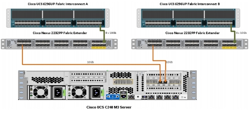
The Cisco UCS C240M3 Rack Server (Capacity Optimized for Pivotal HD with HAWQ configuration) is equipped with Intel Xeon E5-2670 v2 processors, 128GB of memory, Cisco UCS Virtual Interface Card (VIC)1225, LSI MegaRAID SAS 9271 CV-8i storage controller and 12x4TB 7.2K Serial Attached SCSI (SAS) disk drives.
Figure 1 illustrates the physical connectivity of Cisco UCS C240M3 Servers to Cisco Nexus 2232PP Fabric Extenders and Cisco UCS 6296UP Fabric Interconnects.
Figure 1 Fabric Topology
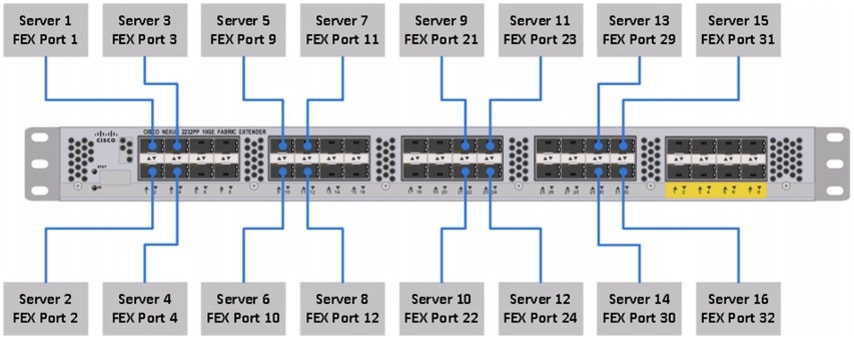
Figure 2 illustrates the ports of the Cisco Nexus 2232PP Fabric Extender connecting Cisco UCS C240M3 Servers. Sixteen Cisco UCS C240M3 Servers are used in the master rack configurations offered by the Cisco.
Figure 2 Connectivity Diagram of Cisco Nexus 2232PP FEX and Cisco UCS C240M3 Servers
For more information on physical connectivity and single-wire management, see:
For more information on physical connectivity illustrations and cluster setup, see:
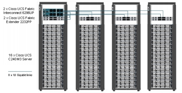
Figure 3 depicts a 64-node cluster, and each link represents 8 x 10 Gigabit link.
Figure 3 64 -Node Cluster Configuration
Software Distributions and Versions
Pivotal HD
Pivotal HD GA version supported is PHD 1.1.1.0 and above. For more information, see:
HAWQ
HAWQ also know as Pivotal Advance Database Service (PADS) is an optional service which is part of Pivotal HD distribution and GA version supported is PADS 1.1.3.0 and above.
RHEL
The Operating System supported is Red Hat Enterprise Linux Server 6.4. For more information on the Linux support, see:
Software Versions
Table 4 describes the software versions tested and validated in this document.
Note
Fabric Configuration
This section provides details for configuring a fully redundant, highly available Cisco UCS 6296 Fabric Interconnect.
1.
2.
3.
4.
5.
6.
7.
8.
9.
Performing Initial Setup of Cisco UCS 6296 Fabric Interconnects
This section describes the steps to perform the initial setup of the Cisco UCS 6296 Fabric Interconnects A and B.
Configure Fabric Interconnect A
Follow these steps to configure the Fabric Interconnect A:
1.
2.
3.
4.
5.
6.
7.
8.
9.
10.
11.
12.
13.
14.
15.
16.
17.
18.
19.
20.
Configure Fabric Interconnect B
Follow these steps to configure the Fabric Interconnect B:
1.
2.
3.
4.
5.
6.
7.
Note
Logging Into Cisco UCS Manager
Follow these steps to login to Cisco UCS Manager.
1.
2.
3.
4.
5.
Upgrading UCSM Software to Version 2.2(1b)
This document assumes the use of UCS 2.2(1b). Refer to Upgrading between Cisco UCS 2.0 Releases to upgrade the Cisco UCS Manager software and UCS 6296 Fabric Interconnect software to version 2.2(1b). Also, make sure the UCS C-Series version 2.2(1b) software bundles is installed on the Fabric Interconnects.
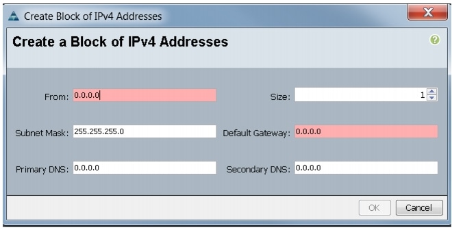
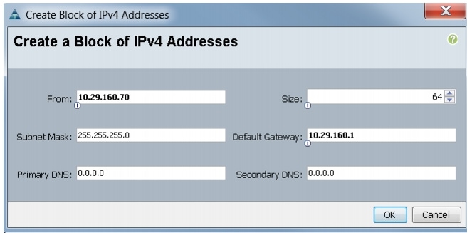
Adding Block of IP Addresses for KVM Access
Follow these steps to create a block of KVM IP addresses for the server access in Cisco UCS environment.
1.
2.
3.
4.
Figure 4 Adding Block of IPv4 Addresses for KVM Access Part 1
5.
Figure 5 Adding Block of IPv4 Addresses for KVM Access Part 2
6.
7.
Figure 6 Adding Block of IPv4 Addresses for KVM Access Part 3
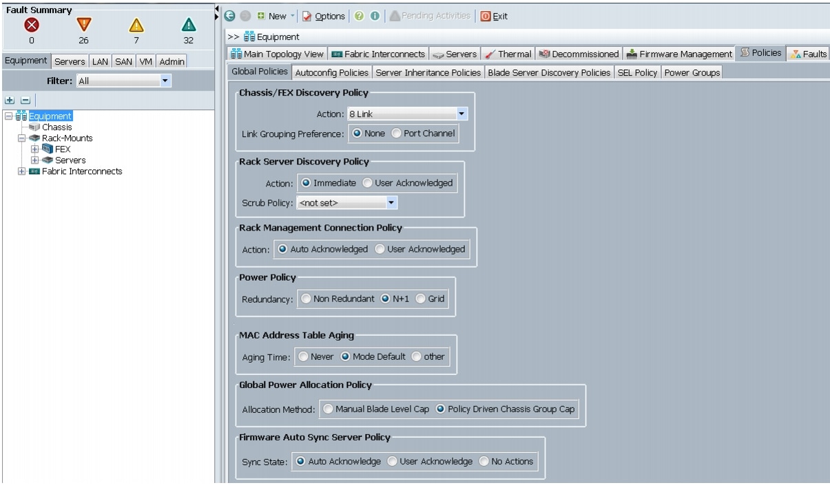
Editing the Chassis/FEX Discovery Policy
This section provides details for modifying the chassis discovery policy. Setting the discovery policy ensures easy addition of the Cisco UCS B-Series chassis or fabric extenders for the Cisco UCS C-Series servers in future.
1.
2.
3.
4.
Figure 7 Editing the Chassis/FEX Discovery Policy
5.
6.
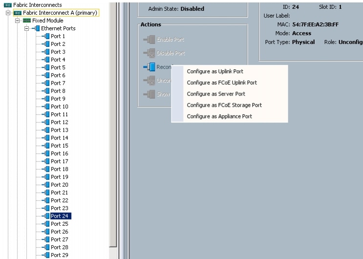
Enabling the Server Ports and Uplink Ports
Follow these steps to enable the server and configure the uplink ports:
1.
2.
3.
4.
5.
6.
7.
8.
9.
10.
11.
12.
Figure 8 Enabling Server Ports
13.
14.
Figure 9 shows all the configured uplink and Server ports.
Figure 9 Server and Uplink Ports Summary
Creating Pools for Service Profile Templates
Creating an Organization
Organizations are used as a means to arrange and restrict access to various groups within the IT organization, and enable multi-tenancy of the compute resources. This document does not use organizations; however, the steps to create an organizations are given for future reference.
Follow these steps to configure an organization in the Cisco UCS Manager:
1.
2.
3.
4.
5.
Creating MAC Address Pools
Follow these steps to create MAC address pools:
1.
2.
3.
4.
5.
6.
7.
8.
9.
10.
Figure 10 Specifying the First MAC Address and Size
11.
Figure 11 Adding MAC Addresses
12.
Configuring VLANs
Table 5 describes the VLANs that are configured in this design solution.
All of the VLANs created should be trunked to the upstream distribution switch connecting the fabric interconnects. In this deployment, vlan160_mgmt is configured for management access and user connectivity, vlan12_HDFS is configured for Hadoop interconnect traffic, and vlan11_DATA is configured for optional secondary interconnect and/or SAN/NAS access, heavy ETL, and so on.
Follow these steps to configure VLANs in Cisco UCS Manager:
1.
2.
3.
4.
Figure 12 Creating VLAN
5.
6.
7.
8.
9.
Figure 13 Creating Management VLAN
10.
11.
12.
13.
14.
15.
16.
17.
18.
Figure 14 Creating VLAN for Data
19.
20.
21.
22.
23.
24.
25.
26.
Figure 15 Creating VLAN for Hadoop Data
Creating Server Pool
A server pool contains a set of servers. These servers typically share the same characteristics such as their location in the chassis, server type, amount of memory, local storage, type of CPU, or local drive configuration. You can manually assign a server to a server pool, or use the server pool policies and server pool policy qualifications to automate the server assignment.
Follow these steps to configure the server pool within the Cisco UCS Manager:
1.
2.
3.
4.
5.
6.
7.
Figure 16 Setting Name and Description of the Server Pool
8.
9.
10.
Figure 17 Adding Servers to the Server Pool
Creating Policies for Service Profile Templates
This section provides you the procedure to create the following policies for the service profile template:
•
•
•
Creating a Host Firmware Package Policy
Firmware management policies allow the administrator to select the corresponding firmware packages for a given server configuration. The components that can be configured include adapters, BIOS, board controllers, FC adapters, HBA options, ROM and storage controller.
Follow these steps to create a host firmware management policy for a given server configuration using the Cisco UCS Manager:
1.
2.
3.
4.
5.
6.
7.
8.
9.
Figure 18 Creating Host Firmware Package
Creating QoS Policies
This section describes the procedure to create the Best Effort QoS Policy and Platinum QoS policy.
Creating the Best Effort Policy
Follow these steps to create the Best Effort Policy:
1.
2.
3.
4.
Figure 19 Creating QoS Policy
5.
6.
7.
8.
9.
10.
11.
Figure 20 Creating BestEffort QoS Policy
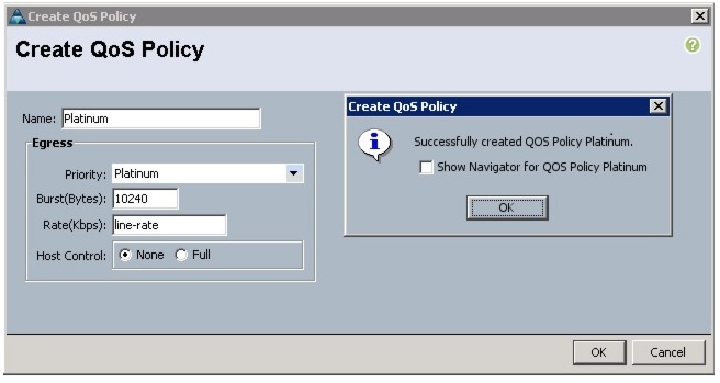
Creating a Platinum Policy
Follow these steps to create the Platinum QoS policy:
1.
2.
3.
4.
5.
6.
7.
8.
9.
10.
11.
Figure 21 Creating Platinum QoS Policy
Setting Jumbo Frames
Follow these steps to set up Jumbo frames and enable the QoS:
1.
2.
3.
4.
5.
6.
7.
8.
Figure 22 Setting Jumbo Frames
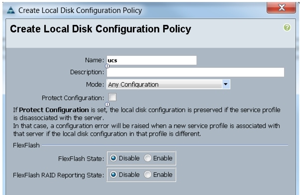
Creating a Local Disk Configuration Policy
Follow these steps to create a local disk configuration in the Cisco UCS Manager:
1.
2.
3.
4.
5.
6.
7.
8.
9.
10.
11.
Figure 23 Configuring Local Disk Policy
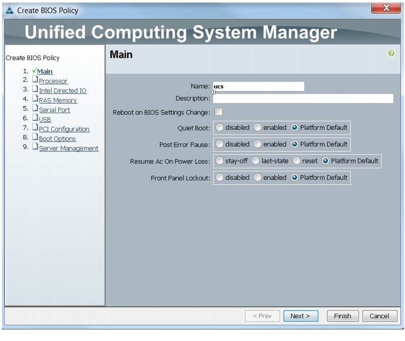
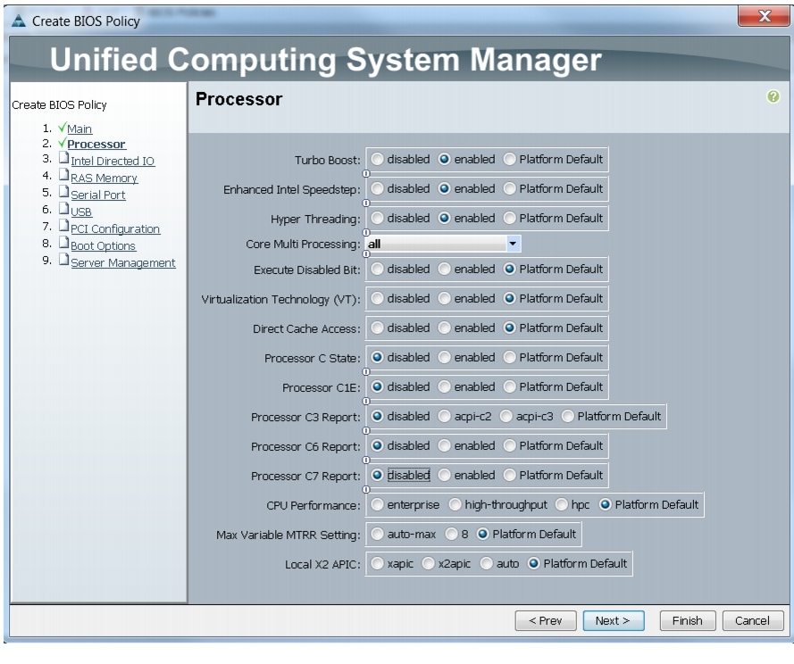
Creating a Server BIOS Policy
The BIOS policy feature in Cisco UCS automates the BIOS configuration process. The traditional mode of setting the BIOS is manual and is often error-prone. By creating a BIOS policy and assigning the policy to a server or group of servers, you can enable transparency within the BIOS settings configuration.
Note
Follow these steps to create a server BIOS policy using the Cisco UCS Manager:
1.
2.
3.
4.
5.
6.
Figure 24 Creating Server BIOS Policy
7.
Figure 25 Creating Server BIOS Policy for Processor
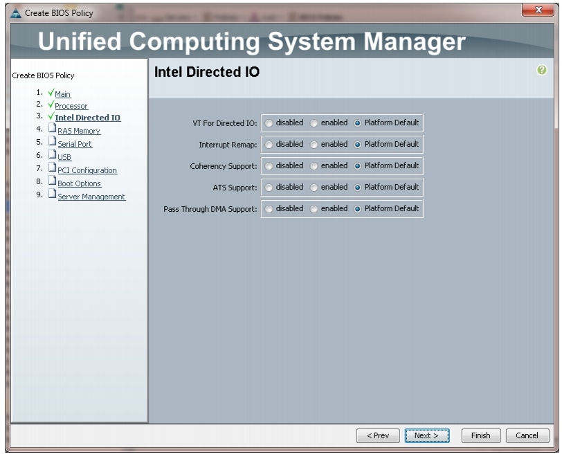
Figure 26 Creating Server BIOS Policy for Intel Directed IO
8.
9.
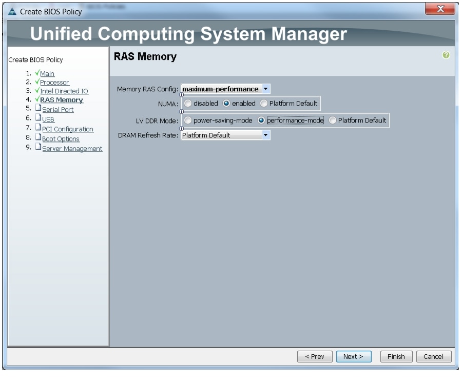
Figure 27 Creating Server BIOS Policy for Memory
10.
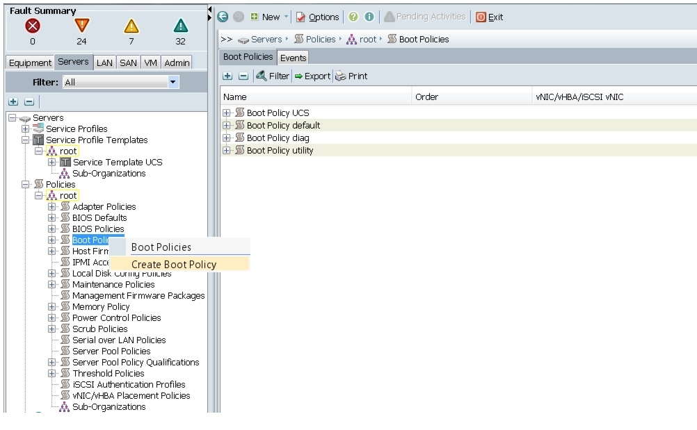
Creating a Boot Policy
Follow these steps to create a boot policy within Cisco UCS Manager:
1.
2.
3.
4.
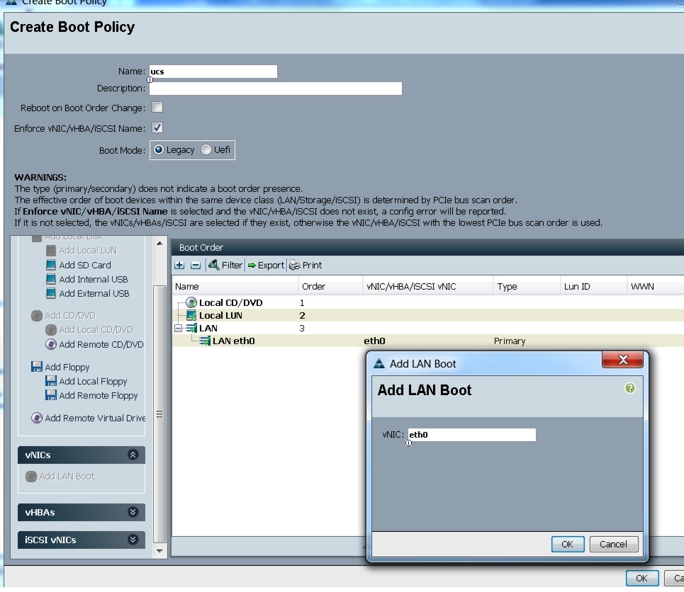
Figure 28 Creating Boot Policy Part 1
5.
6.
7.
8.
9.
10.
11.
12.
Figure 29 Creating Boot Policy Part 2
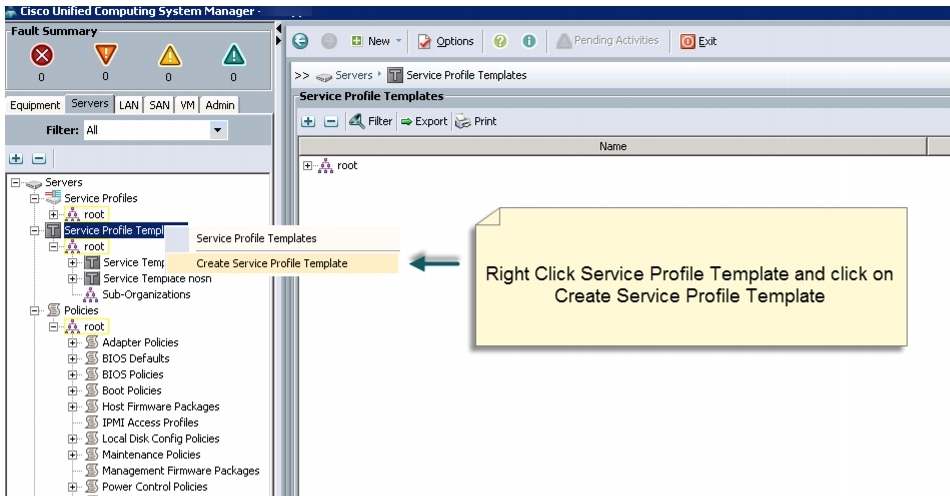
Creating a Service Profile Template
Follow these steps to create a service profile template in Cisco UCS Manager:
1.
2.
3.
Figure 30 Creating Service Profile Template
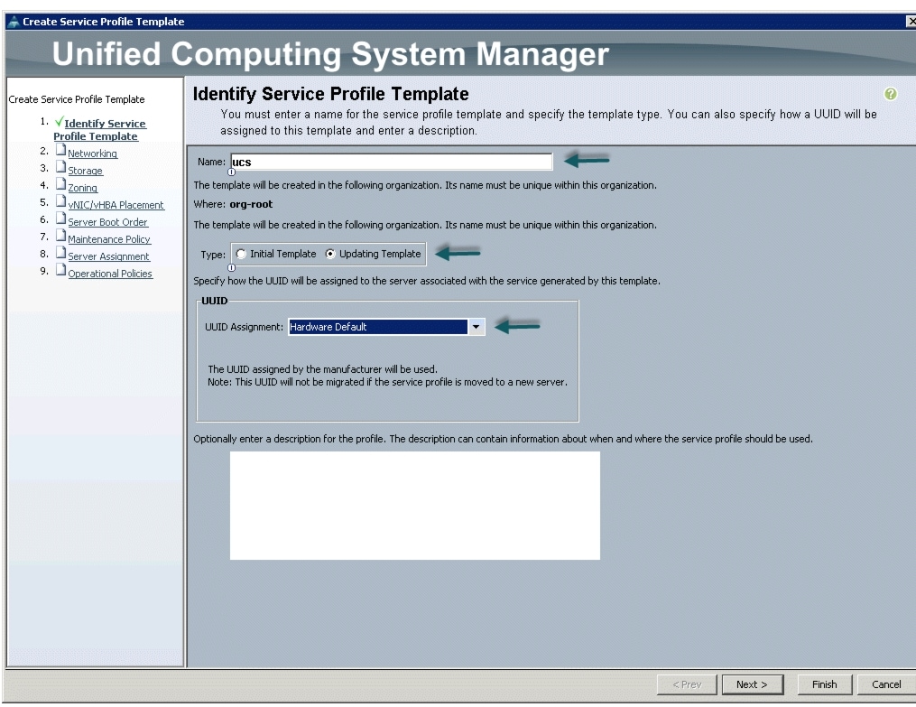
4.
a.
b.
c.
5.
Figure 31 Identify Service Profile Template
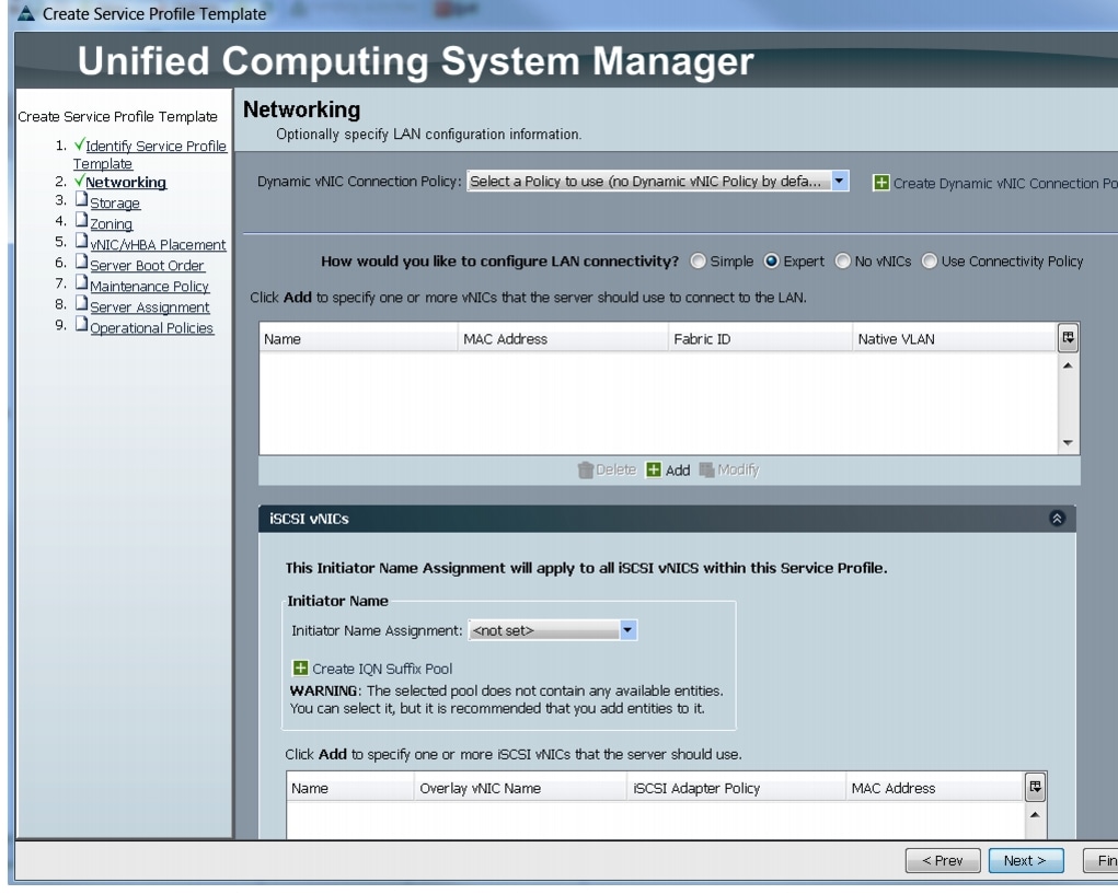
Configuring Network Settings for the Template
In the Networking window, follow these steps to configure the network settings in the Cisco UCS Manager:
1.
2.
3.
Figure 32 Configuring Network Settings for the Template
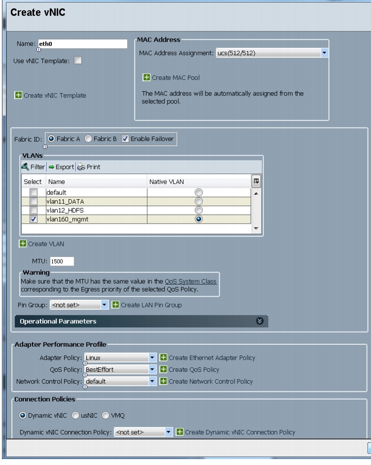
4.
5.
6.
7.
8.
9.
10.
11.
12.
13.
14.
15.
Figure 33 Configuring vNIC eth0
16.
17.
18.
19.
20.
21.
22.
23.
24.
25.
26.
Figure 34 Configuring vNIC eth1
27.
28.
29.
30.
31.
32.
33.
34.
35.
36.
37.
38.
Figure 35 Configuring vNIC eth2
Configuring a Storage Policy for the Template
In the Storage window, follow these steps to configure a storage policy in Cisco UCS Manager:
1.
2.
3.
Figure 36 Configuring Storage settings
4.
Configuring a vNIC/vHBA Placement for the Template
In the vNIC/vHBA window, follow these steps to configure a vNIC/vHBA placement policy in Cisco UCS Manager:
1.
2.
a.
b.
c.
Review to make sure that all vNICs are assigned in the appropriate order.
3.
Figure 37 vNIC/vHBA Placement
Configuring a Server Boot Order for the Template
In the Server Boot Order window, follow these steps to set the boot order for servers in Cisco UCS Manager:
1.
2.
Review to make sure that all the boot devices are created and identified.
3.
4.
Figure 38 Creating Boot Policy
5.
In the Maintenance Policy window, keep the default no policy as we have not created a policy. Click Next to continue to the next window.
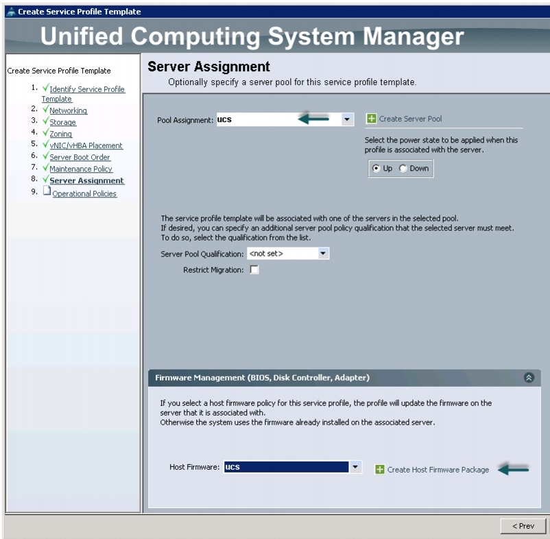
Configuring Server Assignment for the Template
In the Server Assignment window, follow these steps to assign the servers to the pool in Cisco UCS Manager:
1.
2.
3.
Figure 39 Server Assignment
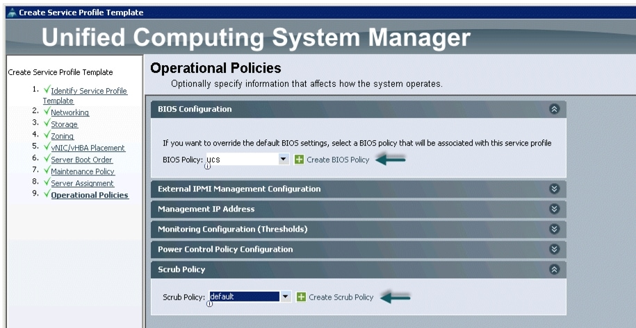
Configuring Operational Policies for the Template
In the Operational Policies window, follow these steps:
1.
2.
3.
Figure 40 Selecting BIOS Policy
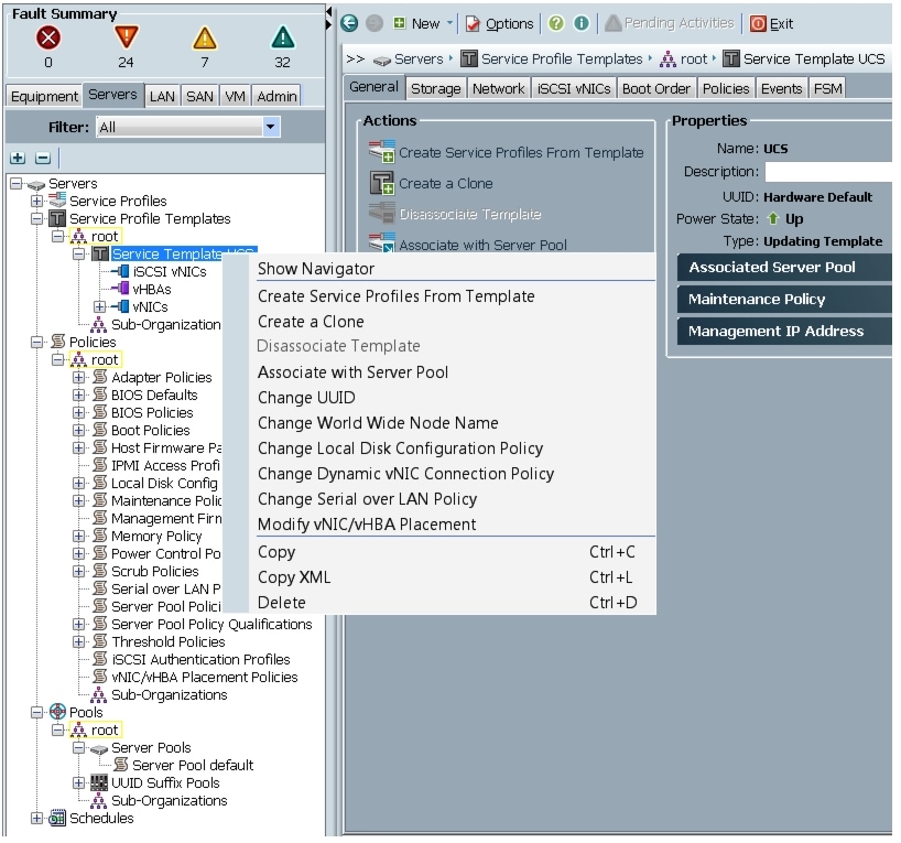
4.
a.
b.
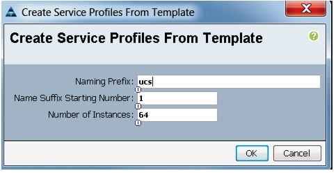
Figure 41 Creating Service Profiles from Template
c.
Figure 42 Selecting Name and Total Number of Service Profiles
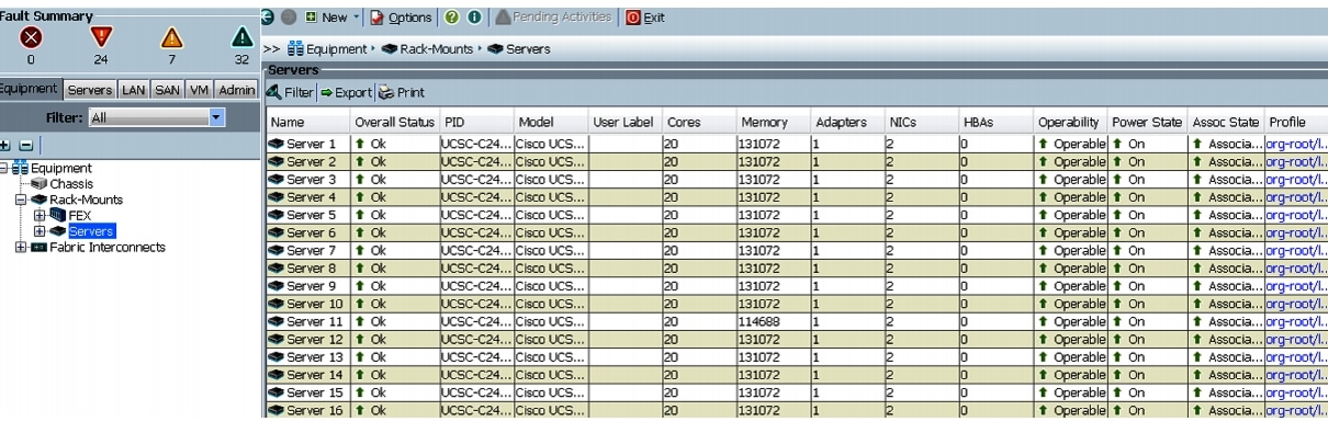
The Cisco UCS Manager discovers the servers and automatically associate these servers with service profiles. Figure 43 illustrates the service profiles associated with all the 64-nodes.
Figure 43 Cisco UCS Manager showing 64 Nodes
Configuring Disk Drives for Operating System on NameNodes
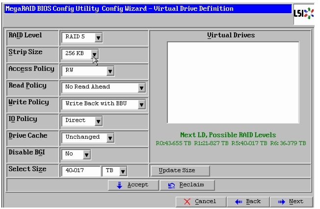
Admin Node, HAWQ Node, Namenode and Secondary Namenode have a different RAID configuration compared to Datanodes. This section details the configuration of disk drives for OS on these nodes. Nodes 1-3 run the Admin and Master Services. Nodes 4-64 are data and compute.
For these Nodes use RAID5 with strip size of 256KB. For this configuration Read policy and Write Policy are No Read Ahead and Write back with BBU respectively.
There are several ways to configure RAID such as:
•
•
•
•
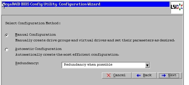
For this deployment, the drives are configured using the LSI WebBIOS Configuration Utility.
Follow these steps to create RAID5 on all the eight disk drives:
1.
a.
b.
2.
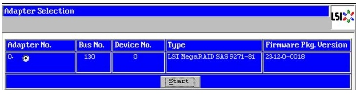
3.
Figure 44 Adapter Selection for RAID Configuration
4.
5.
Figure 45 Clearing Current Configuration on the Controller
6.
7.
8.
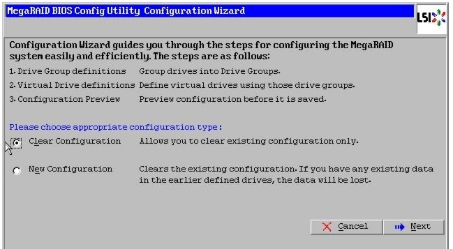
9.
Figure 46 Choosing to Create a New Configuration
10.
Figure 47 Choosing Manual Configuration Method
11.
12.
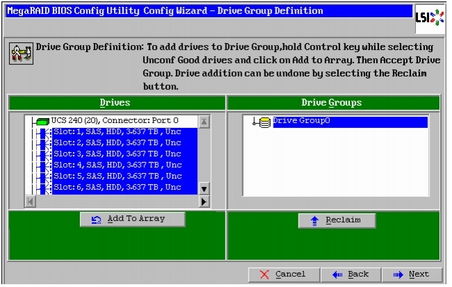
13.
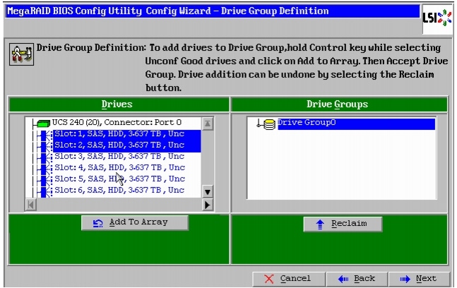
Figure 48 Selecting All the Drives and Adding to Drive Group
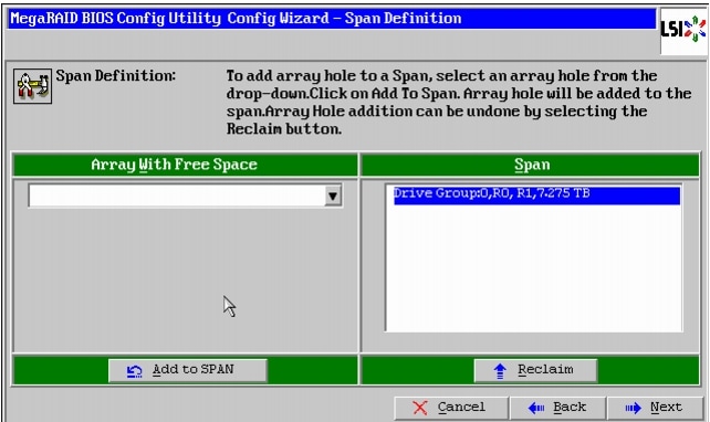
14.
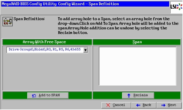
Figure 49 Span Definition Window
15.
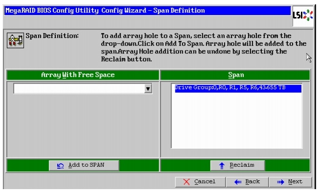
Figure 50 Adding Array Hole to Span
16.
a.
b.
c.
d.
e.
f.
g.
Note
Figure 51 Defining Virtual Drive
17.
18.
19.
20.
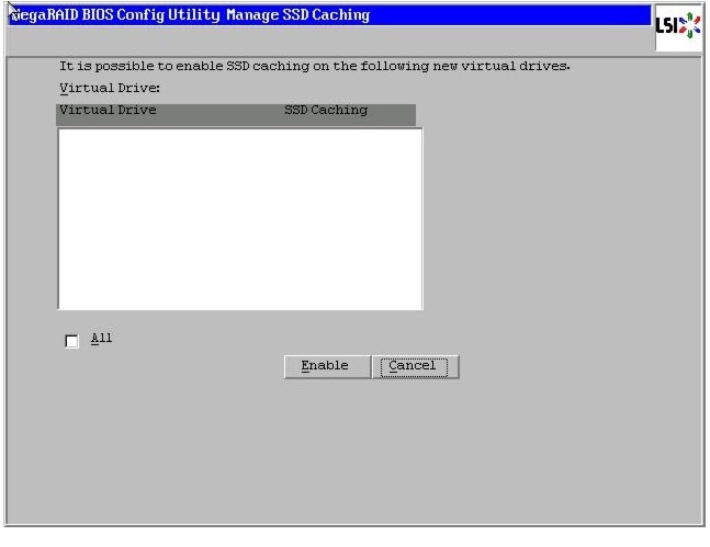
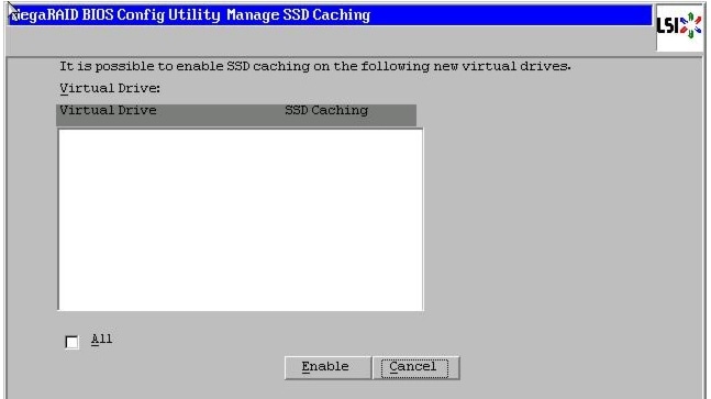
Figure 52 SSD Caching Window
21.
22.
23.
24.
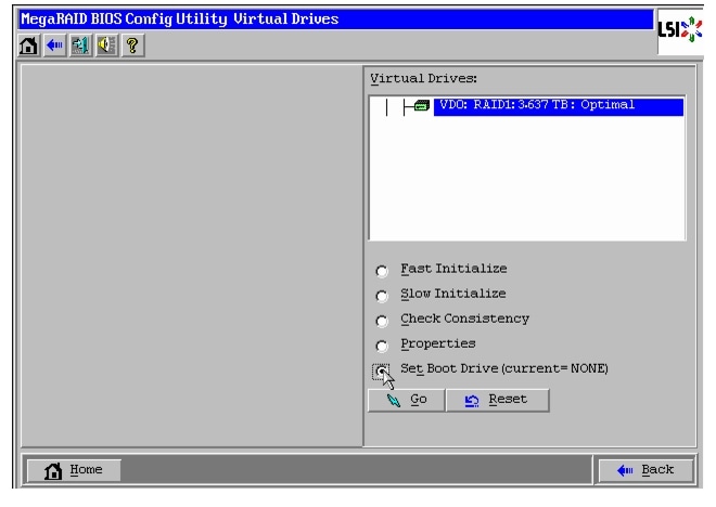
Figure 53 Setting Virtual Drive as Boot Drive
Configuration of disks 3 to 24 are done using Linux based MegaCLI commands described in "Configuring Data Drives on Data Nodes" section.
Configuring Disk Drives for Operating System on DataNodes
Nodes 4 through 64 are configured as data nodes. This section details the configuration of disk drives for OS on the data nodes. As stated above, the focus of this CVD is the Capacity Optimized Configuration featuring 12 4TB LFF disk drives. The first two disk drives are configured as a RAID1 volume with 64KB strip size and the rest individual RAID0 volumes with 1MB strip size. For this configuration Read and write Policy are No Read Ahead and Always write Back respectively.
Note
There are several ways to configure RAID such as:
•
•
•
•
For this deployment, the first disk drive is configured using LSI WebBIOS Configuration Utility and rest is configured using Linux based MegaCLI commands after the OS is installed.
Follow these steps to create RAID1 on the first two disk drives to install the Operating System:
1.
a.
b.
2.
3.
Figure 54 Adapter Selection for RAID Configuration
4.
5.
Figure 55 Clearing Current Configuration on the Controller
6.
7.
8.
9.
Figure 56 Choosing to Create a New Configuration
10.
Figure 57 Choosing Manual Configuration Method
11.
12.
13.
14.
Figure 58 Selecting First Two Drives and Adding to Drive Group
15.
Figure 59 Span Definition Window
16.
a.
b.
Note
c.
d.
e.
f.
g.
Note
Figure 60 Defining Virtual Drive
17.
18.
19.
20.
Figure 61 SSD Caching Window
21.
22.
23.
24.
Figure 62 Setting Virtual Drive as Boot Drive
The steps above can be repeated to configure disks 3-12 or using Linux based MegaCLI commands described in "Configuring Data Drives on Data Nodes" section.
Installing Red Hat Linux 6.4 with KVM
The following section provides detailed procedures for installing Red Hat Linux 6.4.
There are multiple methods to install Red Hat Linux Operating System. The installation procedure described in this design guide uses KVM console and virtual media from Cisco UCS Manager.
1.
2.
3.
4.
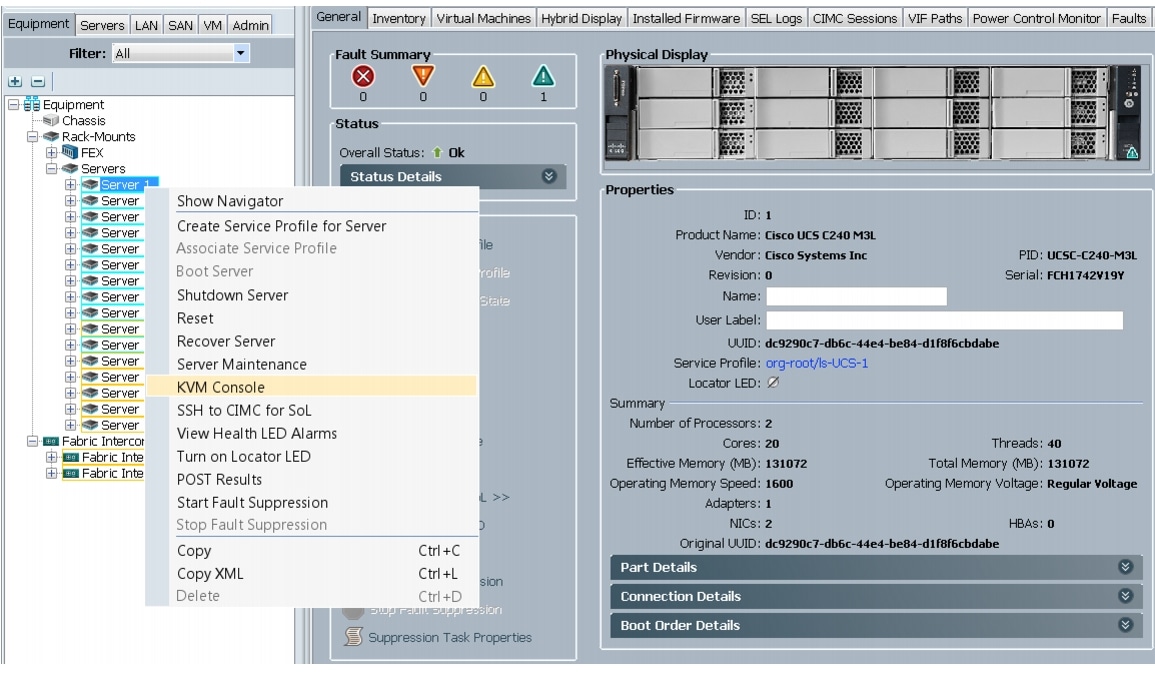
Figure 63 Selecting KVM Console Option
5.
6.
7.
Note
Figure 64 Adding an ISO Image
8.
9.
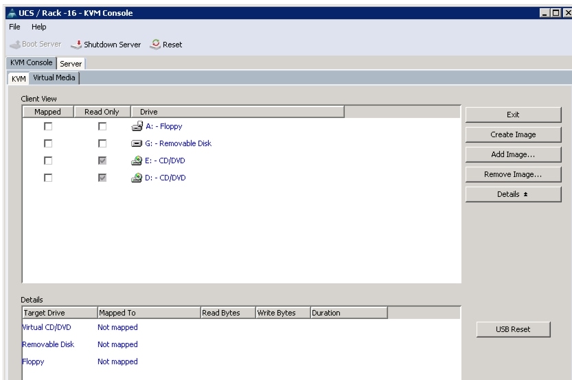
Figure 65 Mapping ISO Image
10.
11.
12.
13.
On reboot, the server detects the presence of the Red Hat Enterprise Linux Server 6.4 install media.
14.
Figure 66 Select Install Option
15.
16.
17.
18.
19.
20.
21.
22.
23.
24.
25.
26.
27.
For this demonstration, the following values have been used:
IP Address: 10.29.160.53
Netmask: 255.255.255.0
Gateway: 10.29.160.1
28.
29.
Figure 67 Configuring Network for eth0
30.
IP Address: 192.168.12.11
Netmask: 255.255.255.0
Figure 68 Configuring Network for eth1
31.
IP Address: 192.168.11.11
Netmask: 255.255.255.0
Note
32.
33.
34.
35.
Figure 69 Selecting Install Option
36.
37.
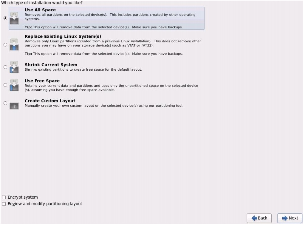
Figure 70 Selecting Type of Installation
38.
39.
Repeat the above steps (1 to 39) to install the Red Hat Linux on servers 2 through 64.
Note
Table 6 describes the hostnames and their corresponding IP addresses.
Post OS Install Configuration
Use one of the three master nodes to install Pivotal Command Center (referred to as Admin Node). Pivotal command center facilitates Install, Management and Monitoring of Pivotal HD. In this document, we have used rhel1 for this purpose.
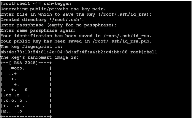
Setting Up Password-less Login
To manage all of the cluster nodes from the admin node we need to setup password-less login. It assists in automating common tasks with Parallel-SSH (pssh) and shell-scripts without having passwords.
Once Red Hat Linux is installed across all the nodes in the cluster, follow these steps in order to enable password less login across all the nodes.
1.
ssh 10.29.160.532.
3.
for IP in {53..116}; do echo -n "$IP -> "; ssh-copy-id -i ~/.ssh/id_rsa.pub
10.29.160.$IP; done
4.
5.
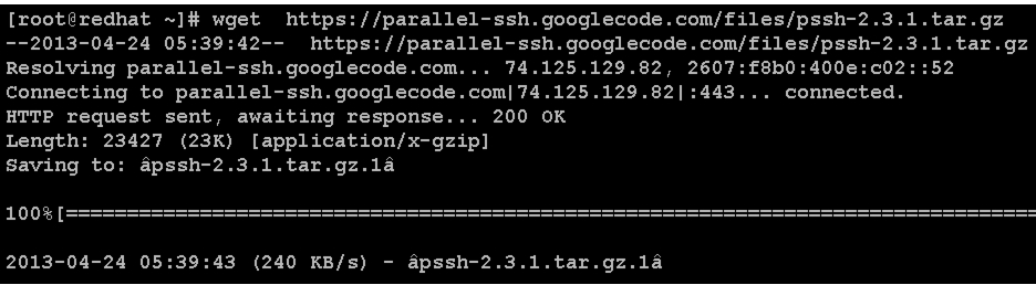
Installing and Configuring Parallel SSH
Installing Parallel-SSH
Parallel-ssh is used to run commands on several hosts at the same time. It takes a file of hostnames and a few common ssh parameters as parameters, and executes the given command in parallel on the specified nodes.
1.
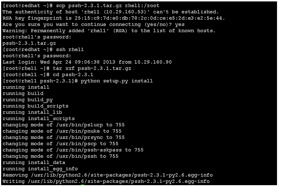
wget https://parallel-ssh.googlecode.com/files/pssh-2.3.1.tar.gz
scp pssh-2.3.1.tar.gz rhel1:/root2.
ssh rhel1tar xzf pssh-2.3.1.tar.gzcd pssh-2.3.1python setup.py install
3.
4.
vi /root/allnodes# This file contains ip address of all nodes of the cluster#used by parallel-shell (pssh). For Details man pssh10.29.160.5310.29.160.5410.29.160.5510.29.160.5610.29.160.5710.29.160.5810.29.160.5910.29.160.6010.29.160.6110.29.160.6210.29.160.6310.29.160.6410.29.160.6510.29.160.6610.29.160.6710.29.160.68...10.29.160.116vi /root/datanodes10.29.160.5510.29.160.5610.29.160.5710.29.160.5810.29.160.5910.29.160.6010.29.160.6110.29.160.6210.29.160.6310.29.160.6410.29.160.6510.29.160.6610.29.160.6710.29.160.68...10.29.160.116Installing Cluster Shell
1.
Cluster shell is available from the Extra Packages for Enterprise Linux (EPEL) repository.
wget
http://dl.fedoraproject.org/pub/epel//6/x86_64/clustershell-1.6-1.el6.noarch.rpm
scp clustershell-1.6-1.el6.noarch.rpm rhel1:/root/2.
yum install clustershell-1.6-1.el6.noarch.rpm3.
For 64 node cluster all: rhel[1-64], rhel[10-64]
Note
Configuring /etc/hosts and DNS
Follow these steps to create the host file across all the nodes in the cluster:
1.
On Admin Node (rhel1)
vi /etc/hosts127.0.0.1 localhost localhost.localdomain localhost4 localhost4.localdomain4::1 localhost localhost.localdomain localhost6 localhost6.localdomain610.29.160.53 rhel1.mgmt10.29.160.54 rhel2.mgmt10.29.160.55 rhel3.mgmt10.29.160.56 rhel4.mgmt10.29.160.57 rhel5.mgmt10.29.160.58 rhel6.mgmt10.29.160.59 rhel7.mgmt10.29.160.60 rhel8.mgmt10.29.160.61 rhel9.mgmt10.29.160.62 rhel10.mgmt10.29.160.63 rhel11.mgmt10.29.160.64 rhel12.mgmt10.29.160.65 rhel13.mgmt10.29.160.66 rhel14.mgmt10.29.160.67 rhel15.mgmt10.29.160.68 rhel16.mgmt...192.168.12.11 rhel1192.168.12.12 rhel2192.168.12.13 rhel3192.168.12.14 rhel4192.168.12.15 rhel5192.168.12.16 rhel6192.168.12.17 rhel7192.168.12.18 rhel8192.168.12.19 rhel9192.168.12.20 rhel10192.168.12.21 rhel11192.168.12.22 rhel12192.168.12.23 rhel13192.168.12.24 rhel14192.168.12.25 rhel15192.168.12.26 rhel16...On Other nodes (rhel2-rhel64)
vi /etc/hosts127.0.0.1 localhost localhost.localdomain localhost4 localhost4.localdomain4::1 localhost localhost.localdomain localhost6 localhost6.localdomain62.
vi /etc/resolv.confnameserver 10.29.160.53
Note
3.
pscp -h /root/allnodes /etc/resolv.conf /etc/resolv.conf4.
service dnsmasq start5.
[root@rhel2 ~]# nslookup rhel1.mgmtServer: 10.29.160.53Address: 10.29.160.53#53Name: rhel1.mgmtAddress: 10.29.160.53[root@rhel2 ~]# nslookup rhel1Server: 10.29.160.53Address: 10.29.160.53#53Name: rhel1Address: 192.168.12.11Creating RedHat Local Repository
To create a repository using RHEL DVD or ISO on the admin node (in this deployment rhel1 is used for this purpose), create a directory with all the required rpms, run the createrepo command and then publish the resulting repository.
1.
mkdir -p /var/www/html/rhelrepo642.
3.
scp rhel-server-6.4-x86_64-dvd.iso rhel1:/rootAssuming the Red Hat ISO file is located in your working directory.
mkdir -p /mnt/rhelisomount -t iso9660 -o loop /root/rhel-server-6.4-x86_64-dvd.iso /mnt/rheliso/4.
cp -r /mnt/rheliso/* /var/www/html/rhelrepo645.
vi /var/www/html/rhelrepo/rheliso.repo[rhel6.4]name=Red Hat Enterprise Linux 6.4baseurl=http://10.29.160.53/rhelrepo64gpgcheck=0enabled=1
Note
6.
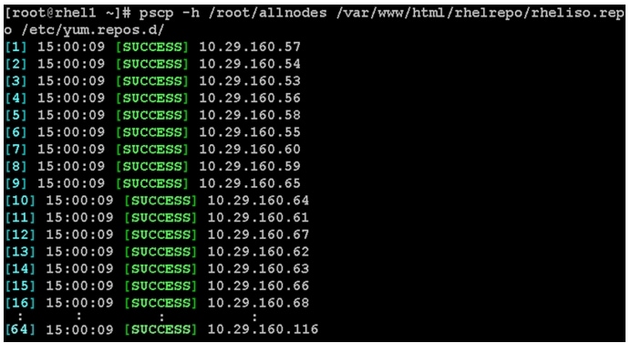
pscp -h /root/allnodes /var/www/html/rhelrepo/rheliso.repo /etc/yum.repos.d/
7.
vi /etc/yum.repos.d/rheliso.repo[rhel6.4]name=Red Hat Enterprise Linux 6.4baseurl=file:///var/www/html/rhelrepo64gpgcheck=0enabled=18.
Creating the Red Hat Repository Database
1.
2.
3.
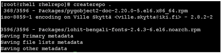
yum -y install createrepocd /var/www/html/rhelrepo64createrepo .yum clean all
Upgrading LSI driver
The latest LSI driver is essential for performance and bug fixes.
To download the latest LSI drivers, see:
1.
2.
3.
pscp -h /root/allnodes kmod-megaraid_sas-v06.601.06.00_rhel6.4-2.x86_64.rpm /root/pssh -h /root/allnodes "rpm -ivh kmod-megaraid_sas-v06.601.06.00_rhel6.4-2.x86_64.rpm"4.
pssh -h /root/allnodes "modinfo megaraid_sas | head -5"Installing httpd
1.
The Red Hat repository is hosted using http on the admin node, and this machine is accessible by all the hosts in the cluster.
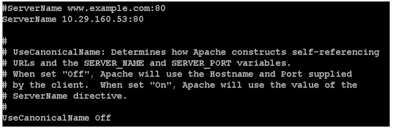
yum -y install httpd2.
/etc/httpd/conf/httpd.confSeverName 10.29.160.53:80
3.
chcon -R -t httpd_sys_content_t /var/www/html/rhelrepo644.
service httpd startchkconfig httpd onEnabling Syslog
Syslog must be enabled on each node to preserve logs regarding killed processes or failed jobs. Modern versions such as syslog-ng and rsyslog are possible, making it more difficult to ascertain if a syslog daemon is present.
Run any of the commands to confirm if the service is properly configured:
clush -B -a rsyslogd -vclush -B -a service rsyslog statusSetting Ulimit
On each node, ulimit -n specifies the number of inodes that can be opened simultaneously. With the default value of 1024, the system appears to be out of disk space and shows no inodes available. This value should be set to 64000 on every node.
Higher values are unlikely to result in an appreciable performance gain.
1.
root soft nofile 64000root hard nofile 64000
Note
2.
clush -B -a ulimit -nThe command should report 64000 as the ulimit.
Disabling SELinux
SELinux must be disabled during the ID installation procedure and cluster setup. SELinux can be enabled after installation and while the cluster is running.
SELinux can be disabled by editing /etc/selinux/config and changing the SELINUX line to SELINUX=disabled.
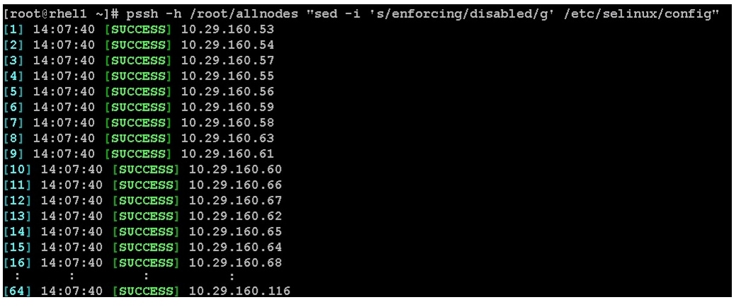
1.
pssh -h /root/allnodes "sed -i 's/SELINUX=enforcing/SELINUX=disabled/g'
/etc/selinux/config"
pssh -h /root/allnodes "setenforce 0"
Note
JDK Installation
Download Java SE 7 Development Kit (JDK)
1.
http://www.oracle.com/technetwork/java/index.html
2.
3.
Install JDK7 on All Node
Create the following script install_jdk.sh to install JDK:
Script install_jdk.sh
# Copy and install JDKcd /tmp/curl http://10.29.160.53/JDK/jdk-7u45-linux-x64.bin -O -Lsh ./jdk-6u41-linux-x64.bin -noregisterCopy script disable_services.sh to all nodes and run the script on all nodes:
pscp -h /root/pssh.hosts /root/install_jdk.sh /root/pssh -h /root/pssh.hosts "/root/install_jdk.sh"Setting TCP Retries
Adjusting the tcp_retries parameter for the system network enables faster detection of failed nodes. Given the advanced networking features of UCS, this is a safe and recommended change (failures observed at the Operating System layer are mostly serious rather than transitory). On each node, set the number of TCP retries to 5 can help detect unreachable nodes with less latency.
1.
net.ipv4.tcp_retries2=52.
clush -B -a sysctl -pDisabling the Linux Firewall
The default Linux firewall settings are far too restrictive for any Hadoop deployment. Since the Cisco UCS Big Data deployment is performed in the isolated network, there is no need to leave the iptables service running.
1.
pssh -h /root/allnodes "service iptables stop"
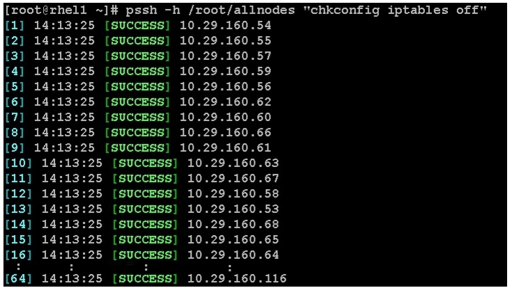
2.
pssh -h /root/allnodes "chkconfig iptables off"
Configuring Data Drives on Data Nodes
The first two disk drives are configured for the Operating System on the nodes, rhel1 and rhel2, as shown in "Configuring Disk Drives for Operating System on NameNodes" section. The remaining disk drives can be configured similarly or by using MegaCli.
1.
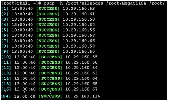
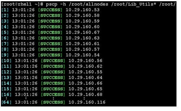
scp /root/MegaCli64 rhel1:/root/scp /root/Lib_Utils-1.00-08.noarch.rpm rhel1:/root/scp /root/Lib_Utils2-1.00-01.noarch.rpm rhel1:/root/2.
pscp -h /root/allnodes /root/MegaCli64 /root/
pscp -h /root/allnodes /root/Lib_Utils* /root/
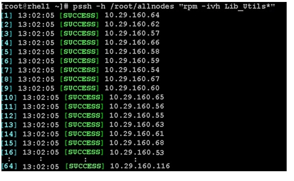
3.
pssh -h /root/allnodes "rpm -ivh Lib_Utils*"
The first two disk drives are configured for the Operating System on the nodes, rhel4 to rhel64 as shown in "Configuring Disk Drives for Operating System on DataNodes" section. The remaining disk drives can be configured similarly or by using MegaCli.
Run the following command from the admin node to create the virtual drives with RAID 0 configurations on all the DataNodes.
pssh -h /root/datanodes "./MegaCli64 -cfgeachdskraid0 WB RA direct NoCachedBadBBU
strpsz1024 -a0"
WB: Write back
RA: Read Ahead
NoCachedBadBBU: Do not write cache when the BBU is bad
Strpsz1024: Strip Size of 1024K
Note
Configuring the Filesystem for DataNodes
This section describes the procedure to configure the filesystem for DataNodes.
1.
To create partition tables and file systems on the local disks of each nodes, run the following script as the root user on all the nodes.
vi /root/driveconf.sh#!/bin/bashdisks_count=`lsblk -id | grep sd | wc -l`if [ $disks_count -eq 12 ]; thenecho "Found 12 disks"elseecho "Found $disks_count disks. Expecting 12. Exiting.."exit 1fi[[ "-x" == "${1}" ]] && set -x && set -v && shift 1for X in /sys/class/scsi_host/host?/scandoecho '- - -' > ${X}donecount=1for X in /dev/sd?doecho $Xif [[ -b ${X} && `/sbin/parted -s ${X} print quit|/bin/grep -c boot` -ne 0 ]]thenecho "$X bootable - skipping."continueelseY=${X##*/}1/sbin/parted -s ${X} mklabel gpt quit/sbin/parted -s ${X} mkpart 1 6144s 100% quit/sbin/mkfs.xfs -f -q -l size=65536b,lazy-count=1,su=256k -d sunit=1024,swidth=6144 -r extsize=256k -L ${Y} ${X}1(( $? )) && continue/bin/mkdir -p /mnt/disk$count(( $? )) && continue/bin/mount -t xfs -o allocsize=128m,noatime,nobarrier,nodiratime ${X}1 /mnt/disk$count(( $? )) && continueecho "LABEL=${Y} /mnt/disk$count xfs allocsize=128m,noatime,nobarrier,nodiratime 0 0" >> /etc/fstab((count++))fidone
Note
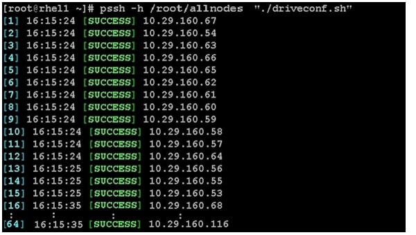
2.
pscp -h /root/datanodes /root/driveconf.sh /root/3.
pssh -h /root/datanodes "./driveconf.sh"
Installing Pivotal HD Using Pivotal Command Center
Pivotal Command Center (PCC) supports both UI as well as CLI interface to install the Pivotal HD and HAWQ services on the cluster.
This section provides an overview of the installation steps using GUI approach. Each step is covered in more detail in the documentation links referenced below. The installation of Pivotal HD requires installation of Pivotal Command Center (PCC) first. Using the command center Pivotal HD is configured, deployed and monitored.
•
•
http://bitcast-a.v1.o1.sjc1.bitgravity.com/greenplum/pivotal-docs/PCC_21_User.pdf
The instructions provided in this section gives an overview on the installation steps. For more detailed information on each of these steps go the Pivotal links mentioned above.
Role Assignment
The install wizard attempts to assign the master nodes for various services that have been selected to appropriate hosts in the cluster. Reconfigure the service assignment to match Table 7.
Note
•
•
Installing Command Center
1.
# scp ./PCC-2.1.x.version.build.os.x86_64.tar.gz host:/root/phd/
2.
# cd /root/phd
# tar --no-same-owner -zxvf PCC-2.1.x.version.build.os.x86_64.tar.gz
3.
Note
Example:
# lsPCC-2.1.x.versionPCC-2.1.x.version.build.os.x86_64.tar.gz# cd PCC-version# ./installThis will display the installation progress information on the screen. Once the installation successfully completes, installation success message is displayed on the screen.
Once the cluster is configured and deployed, the cluster status can be viewed by going to the following url: https://<CommandCenterHost>:5443/status
4.
Pivotal Command Center uses HTTPS to secure data transmission between the client browser and the server. By default, the installation script generates a self-signed certificate. Alternatively user can provide their own Certificate and Key by following these steps:
–
–
–
–
–
–
service commander restart
5.
$ service commander status
6.
su - gpadmin
Repo to Install PHD Services
Once you have Pivotal Command Center installed, you need to import and enable the PHD services (PHD, PHDTools, and HAWQ). You can use the import utility to sync the RPMs from the specified source location into the Pivotal Command Center (PCC) local yum repository of the Admin Node. This allows the cluster nodes to access the RPMs.
1.
2.
For PHD, if the file is a tar.gz or tgz, use:
tar zxf PHD-1.1.x-x.tgz
If the file is a tar, use:
tar xf PHD-1.1.x-x.tar
For Pivotal ADS, if the file is a tar.gz or tgz, use
tar zxf PADS-1.1.x-x.tgz
If the file is a tar, use:
tar xf PADS-1.1.x-x.tar
For PHDTools, if the file is a tar.gz or tgz, use
tar zxf PHDTools-1.1.x-x.tgz
If the file is a tar, use:
tar xf PHDTools-1.1.x-x.tar
Enable the PHD Services
1.
# icm_client import -s <PATH TO EXTRACTED PHD TAR BALL>For example:
# icm_client import -s PHD-1.1.x-x/2.
# icm_client import -s <PATH TO EXTRACTED PADS TAR BALL>For example:
# icm_client import -s PADS-1.1.x-x/For more information, see the log file located at:/var/log/gphd/gphdmgr/gphdmgr-import.log3.
# icm_client import -s <PATH TO EXTRACTED PHDTools TAR BALL>For example:
# icm_client import -s PHDTools-1.1.x-x/For more information, see the log file located at:
/var/log/gphd/gphdmgr/gphdmgr-import.logLaunching Pivotal Command Center
Launch a browser and navigate to the host on which Command Center was installed. For example:
https://rhel1:5443
The Command Center login page is launched in the browser. The default username/password is gpadmin/Gpadmin1.
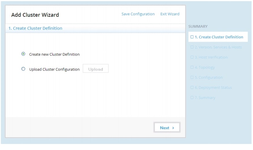
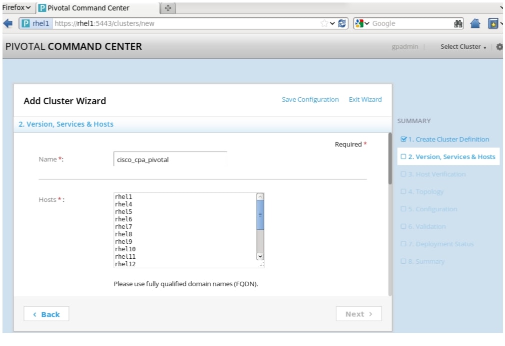
Configuring and Deploying a Cluster
After login into Pivotal Command Center, the Cluster Status page appears. From here, we are able to launch the Add Cluster Wizard through which we can configure and deploy a Pivotal HD Cluster, as follows:
1.
Figure 71 Adding Cluster: Creating Cluster Definition Window
The Wizard allows to create a new configuration from scratch or upload and edit any existing configuration. The Summary panel along the right shows the progress of cluster configuration and deployment.
2.
–
–
3.
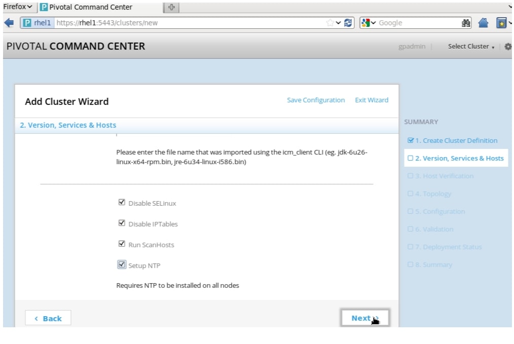
Figure 72 Adding Cluster: Versions, Services and Hosts Window (part 1)
4.
Note
a.
Note
b.
c.
d.
e.
Note
f.
g.
h.
i.
Click Next.
Figure 73 Adding Cluster: Versions, Services and Hosts Window (part 2)
5.
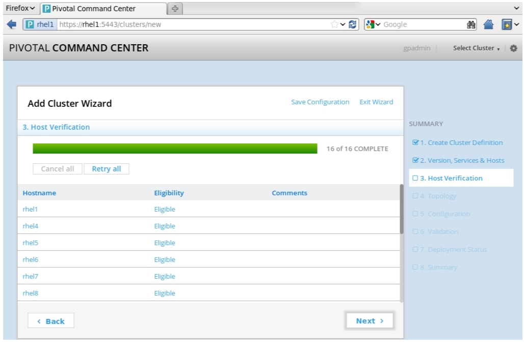
The Host Verification page opens. This step may take a few minutes, it verifies connections to the hosts that were just set up. Once the Eligibility field changes from Pending, to Eligible for all hosts, you can click Next. You can see the errors and other related information displayed in the comments fields.
Click Next.
Figure 74 Adding Cluster: Host Verification Window
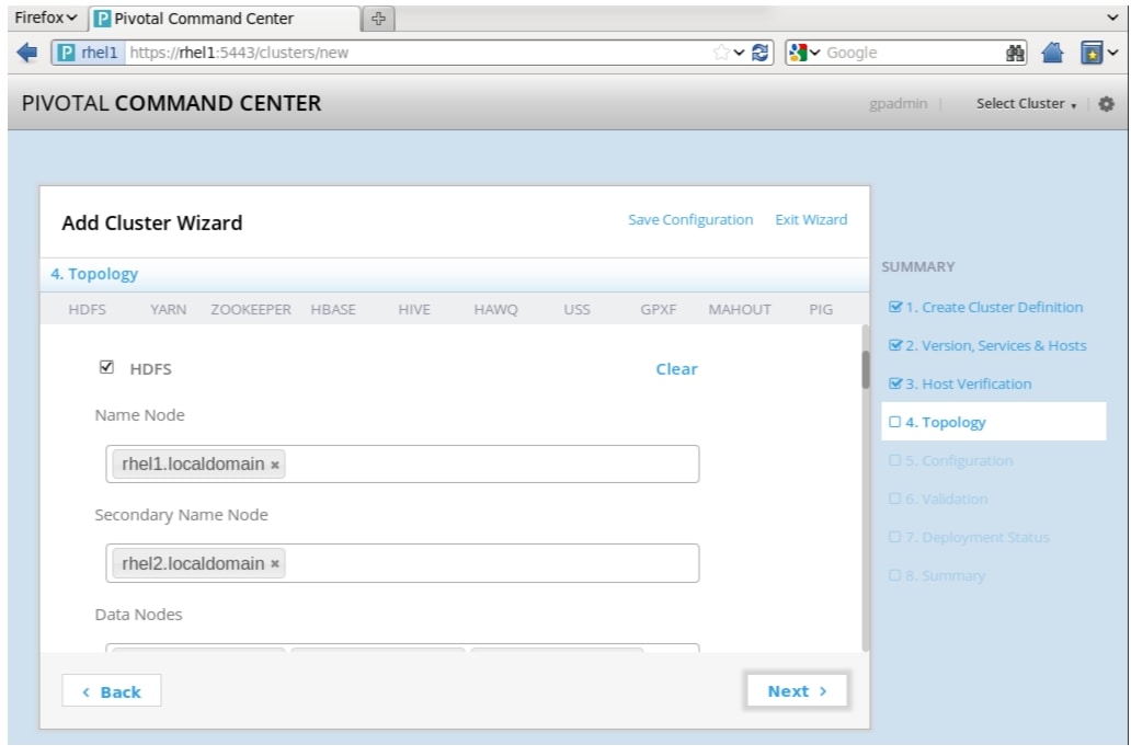
6.
This is the section where you specify the roles to be installed on the hosts. Follow suggestions in Table 7 to assign roles to the Cluster.
Figure 75 Adding Cluster: Topology Window
Note
Each service has its own section on this page; you can use the top menu options as shortcuts to those sections on the page, or simply scroll down to each section.
Type the text in the appropriate text boxes and press Enter or Tab, the text will change appearance and appear enclosed in a box, which means that the entry has been accepted.
At any point during this stage you can click Save Configuration at the top right of the page. This saves the configuration file and downloads it. Once saved, a link to the configuration file appears at the bottom of the page. Click on the link to open and view the clusterConfig.xml file.
Note
These are the roles that need to have installation nodes defined:
a.
b.
c.
d.
e.
f.
g.
h.
i.
j.
k.
Click Next once you have finished role-mapping.
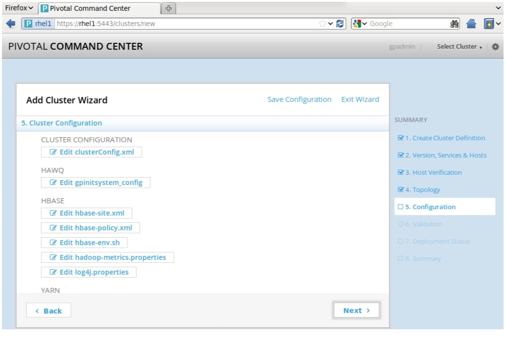
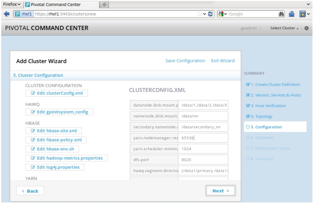
7.
This page displays a list of all configuration files that define this cluster; the clusterConfig.xml (to edit service configuration global values) as well as the service specific configuration files.
All these configuration files are populated with the values that were already entered or with the default values.
a.
b.
Figure 76 Adding Cluster: Cluster Configuration Window
Configuration Directives for PHD Services
This sub-section suggests the specific configuration settings to be used during the deployment of following PHD services using Pivotal Command Center; these settings are primarily based on the CPA v2 cluster hardware configuration. Pivotal Command Center will provide the optimal values for the rest of the configuration, which user can also review, and change as necessary.
Following PHD services are considered for configuration tuning:
•
•
•
Use options listed in table at the time of deploying the new cluster or stop all the services before reconfiguring the cluster. Pivotal Command Center will use the optimal configuration settings for the parameters not specified in Table 8 but you can always review and change them per your needs.
Cluster Services - Global Configuration Variables (Cluster Config.xml)
Table 8 provides the list of global configuration variables of the cluster services.
Figure 77 Adding Cluster: Cluster Configuration Window (part 2)
HDFS
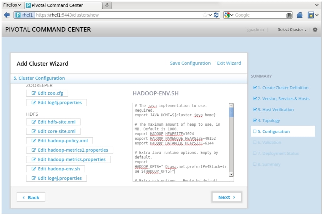
hadoop-env.sh
Set the following variables in hadoop-env.sh with values as specified:
Figure 78 Adding Cluster: Cluster Configuration Window (part 3)
Note
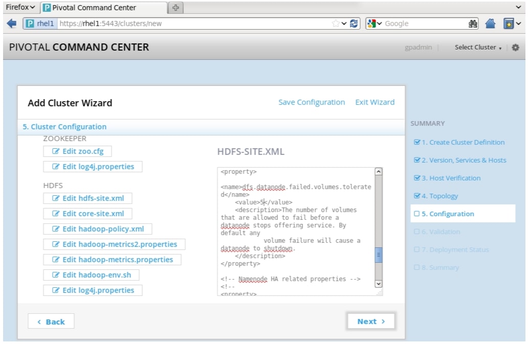
export HADOOP_HEAPSIZE=1024export HADOOP_NAMENODE_HEAPSIZE=49152export HADOOP_DATANODE_HEAPSIZE=6144# Extra Java runtime options. Empty by default.export HADOOP_OPTS="-Djava.net.preferIPv4Stack=true ${HADOOP_OPTS}"# Extra ssh options. Empty by default.export HADOOP_SSH_OPTS="-o ConnectTimeout=5 -o SendEnv=HADOOP_CONF_DIR"# Set Hadoop-specific environment variables here.# Command specific options appended to HADOOP_OPTS when specifiedexport HADOOP_NAMENODE_OPTS="-Dcom.sun.management.jmxremote -Xms${HADOOP_NAMENODE_HEAPSIZE}m -Xmx${HADOOP_NAMENODE_HEAPSIZE}m -Dhadoop.security.logger=INFO,DRFAS -Dhdfs.audit.logger=INFO,DRFAAUDIT -XX:ParallelGCThreads=8 -XX:+UseParNewGC -XX:+UseConcMarkSweepGC -verbose:gc -XX:+HeapDumpOnOutOfMemoryError -XX:+PrintGCDetails -XX:+PrintGCTimeStamps -XX:+PrintGCDateStamps -Xloggc:${HADOOP_LOG_DIR}/hadoop-hdfs-namenode-`date +'%Y%m%d%H%M'`.gclog -XX:ErrorFile=${HADOOP_LOG_DIR}/hs_err_pid%p.log $HADOOP_NAMENODE_OPTS"export HADOOP_SECONDARYNAMENODE_OPTS="-Dcom.sun.management.jmxremote -Xms${HADOOP_NAMENODE_HEAPSIZE}m -Xmx${HADOOP_NAMENODE_HEAPSIZE}m Dhadoop.security.logger=INFO,DRFAS -Dhdfs.audit.logger=INFO,DRFAAUDIT -XX:ParallelGCThreads=8 -XX:+UseParNewGC -XX:+UseConcMarkSweepGC -verbose:gc -XX:+HeapDumpOnOutOfMemoryError -XX:+PrintGCDetails -XX:+PrintGCTimeStamps -XX:+PrintGCDateStamps -Xloggc:${HADOOP_LOG_DIR}/hadoop-hdfs-secondary-namenode-`date +'%Y%m%d%H%M'`.gclog -XX:ErrorFile=${HADOOP_LOG_DIR}/hs_err_pid%p.log $HADOOP_SECONDARYNAMENODE_OPTS"export HADOOP_DATANODE_OPTS="-Dcom.sun.management.jmxremote -Xms${HADOOP_DATANODE_HEAPSIZE}m -Xmx${HADOOP_DATANODE_HEAPSIZE}m -Dhadoop.security.logger=ERROR,DRFAS $HADOOP_DATANODE_OPTS"export HADOOP_BALANCER_OPTS="-Dcom.sun.management.jmxremote -server -Xmx${HADOOP_HEAPSIZE}m $HADOOP_BALANCER_OPTS"# The following applies to multiple commands (fs, dfs, fsck, distcp etc)export HADOOP_CLIENT_OPTS="-Xmx${HADOOP_HEAPSIZE}m $HADOOP_CLIENT_OPTS"hdfs-site.xml
Add or reset the values for the following properties in the hdfs-site.xml.
Table 9 Adding/ Resetting Values in hdfs-site.xml
dfs.stream-buffer-size
131072
dfs.datanode.failed.volumes.tolerated
5
Figure 79 Adding Cluster: Cluster Configuration Window (part 4)
YARN
yarn-env.sh
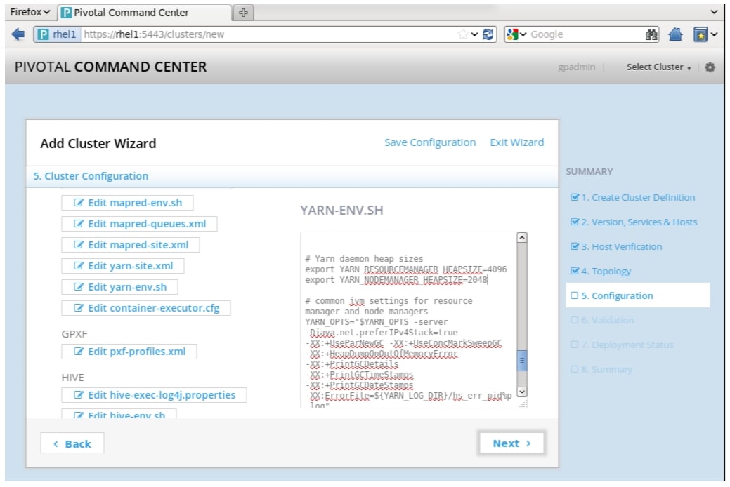
Set the following values for Yarn Resource Manager and Node Manager in the yarn-env.sh file.
Figure 80 Adding Cluster: Cluster Configuration Window (part 5)
Note
export YARN_RESOURCEMANAGER_HEAPSIZE=4096export YARN_NODEMANAGER_HEAPSIZE=2048# Common JVM settings for resource manager and node managersexport YARN_OPTS="$YARN_OPTS -server -Djava.net.preferIPv4Stack=true-XX:+UseParNewGC-XX:+UseConcMarkSweepGC -XX:+HeapDumpOnOutOfMemoryError -XX:+PrintGCDetails-XX:+PrintGCTimeStamps -XX:+PrintGCDateStamps-XX:ErrorFile=${YARN_LOG_DIR}/hs_err_pid%p.log"# Yarn resource manager related jvm settingsexport YARN_RESOURCEMANAGER_OPTS="$YARN_RESOURCEMANAGER_OPTS -Xloggc:${YARN_LOG_DIR}/hadoop-yarn-resourcemanager-`date +'%Y%m%d%H%M'`.gclog"# Yarn node manager related jvm settingsexport YARN_NODEMANAGER_OPTS="$YARN_NODEMANAGER_OPTS -Xloggc:${YARN_LOG_DIR}/hadoop-yarn-nodemanager-`date +'%Y%m%d%H%M'`.gclog"Once you have completed all your edits, click Deploy.
8.
a.
b.
9.
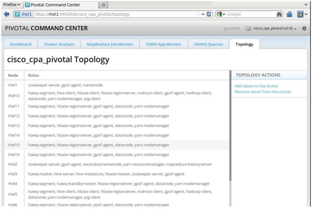
Once your cluster has successfully deployed, you can view a summary of the cluster and Topology view by clicking on Status and choosing Topology, which would include the various roles selected as shown Figure 81.
Figure 81 Cluster Summary and Topology
Post Installation for HAWQ
You need to exchange SSH keys between HAWQ Master and Segment Nodes to complete HAWQ installation.
1.
2.
# ssh <HAWQ_MASTER># source /usr/local/hawq/greenplum_path.sh# /usr/local/hawq/bin/gpssh-exkeys -f ./HAWQ_Segment_Hosts.txtStarting the Cluster
To start the cluster, click Actions. Start on the Cluster Status page. Cluster can also be started from the PCC admin server (rhel1 in this case) using the command:
# icm_client start -l <cluster-name>To list the cluster details, from the PCC admin server run
# icm_client listInitializing HAWQ
As gpadmin ssh to the HAWQ master, the run the following:
# source /usr/local/hawq/greenplum_path.sh# /etc/init.d/hawq initYou have now completed your cluster configuration and deployment.
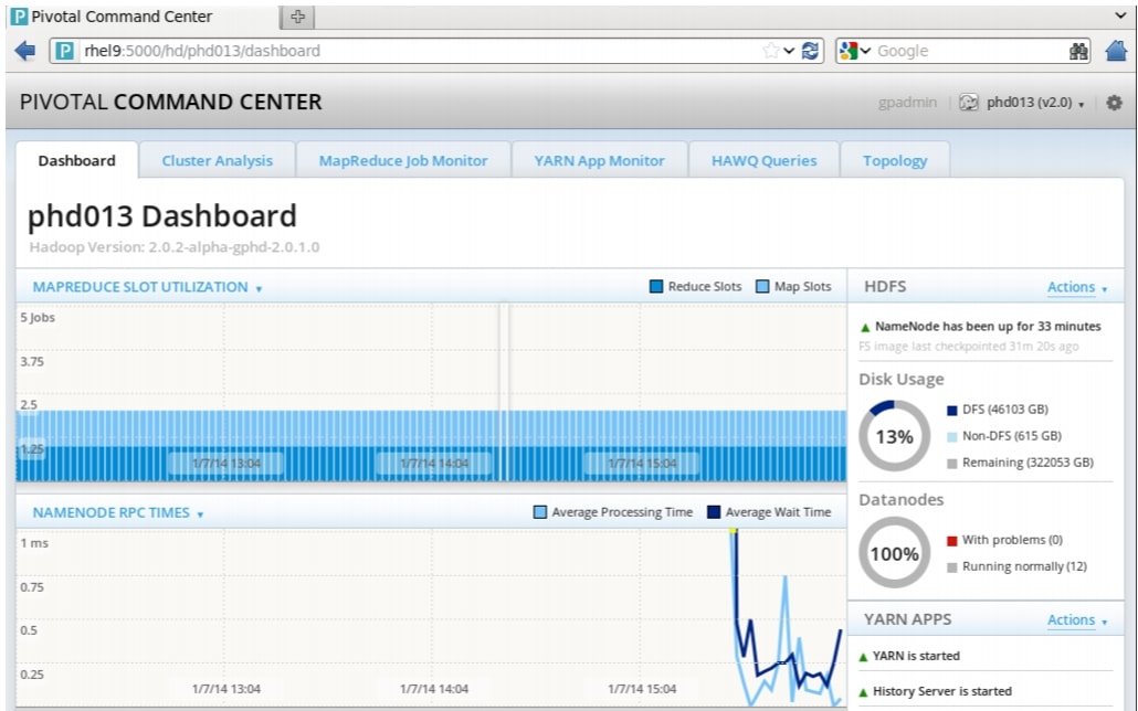
Pivotal Command Center Dashboard
The Pivotal Command Center UI can now be utilized to review the status of the cluster. The dashboard gives a high level view of a cluster at a glance. You are able to view the status of the most important cluster services, such as HDFS and YARN, and allows to start and stop each of the services individually. It also shows how the most important cluster metrics are trending in a visual way.
The graphs provide a unified view of the state of your system. They are also useful in detecting outliers and pinpointing specific problems that may be present in the cluster.
Figure 82 Pivotal Command Center: Dashboard
Conclusion
Hadoop has become a popular data management across all verticals. The Cisco CPA v2 for Big Data with Pivotal HD for Apache Hadoop along with HAWQ offers true SQL processing on enterprise grade Hadoop with Yarn. Further, it offers a dependable deployment model that offer a fast and predictable path for businesses to unlock value in big data.
The configuration detailed in the document can be extended to clusters of various sizes depending on what application demands. Up to 160 servers (10 racks) can be supported with no additional switching in a single UCS domain. Each additional rack requires two Cisco Nexus 2232PP 10GigE Fabric Extenders and 16 Cisco UCS C240 M3 Rack-Mount Servers. Scaling beyond 10 racks (160 servers) can be implemented by interconnecting multiple UCS domains using Nexus 6000/7000 Series switches, scalable to thousands of servers and to hundreds of petabytes storage, and managed from a single pane using Cisco UCS Central.
Bill of Material
This section provides the hardware and software components used in the design setup for deploying the 64-node Capacity Optimized Cluster and Capacity Optimized for Pivotal HD and HAWQ Cluster.
Table 10 provides the BOM for the master rack for Capacity Optimized Cluster. Table 11 provides the BOM for expansion racks (rack 2 to 4) for Capacity Optimized Cluster.
Table 12 provides the BOM for the master rack for Capacity Optimized for Pivotal HD and HAWQ Cluster. Table 13 provides the BOM for expansion racks (rack 2 to 4) for Capacity Optimized for Pivotal HD and HAWQ Cluster. Table 14 and Table 15 describe the BOM for the software components.
Table 14 RedHat Enterprise Linux License
RHEL-2S-1G-3A
Red Hat Enterprise Linux
64
CON-ISV1-RH2S1G3A
3 year Support for Red Hat Enterprise Linux
64