-
Cisco TelePresence System 3000 Assembly, Use & Care, and Field Replacement Unit Guide
-
Preface
-
Overview
-
Building the Display Assembly
-
Mounting and Leveling the Plasma Displays
-
Building the Lighting Assembly
-
Building the Display Shelves
-
Building the Table Assembly
-
Assembling the Remaining Cisco TelePresence Elements
-
Routing Power and Signal Cables
-
First-Time Setup
-
Use and Care Guide
-
Field-Replaceable Unit Guide
-
Appendix A: Parts List Sorted by Carton
-
Appendix B: Region- and Country-Specific Equipment
-
Table Of Contents
Building the Display Assembly
Revised: March 25, 2009, OL-14521-01Parts List
CautionThe display structures are unstable during assembly. Use caution, and support all structures as required.
Warning
Note
Step 1
Figure 2-1 Leveling feet
Note
Step 2
Note
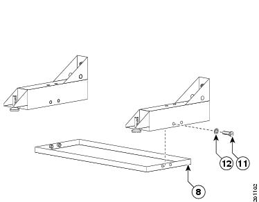
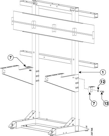
Figure 2-2 Codec Safety trays
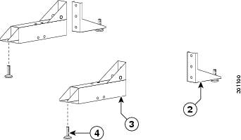
Step 3
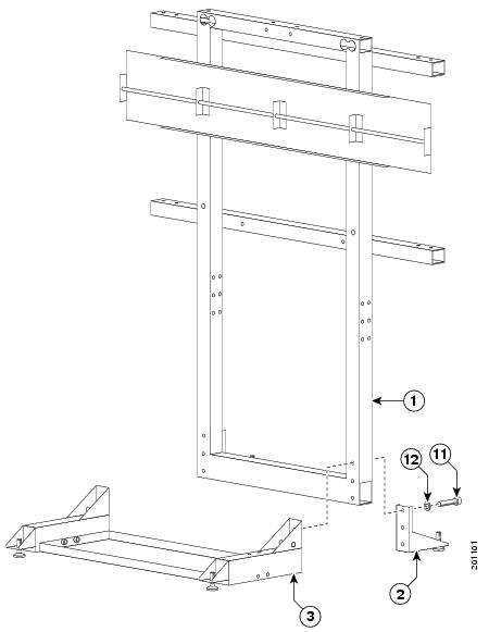
Figure 2-3 Rear and Front Foot stabilizers
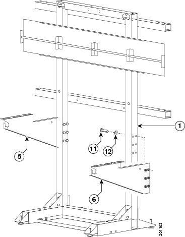
Step 4
Figure 2-4 Left and Right Display Shelf supports
Step 5
Figure 2-5 Display Tilt brackets
Note
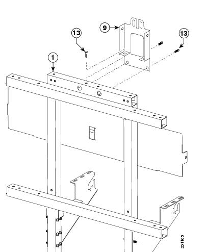
Step 6
Figure 2-6 Camera Assembly bracket
Note
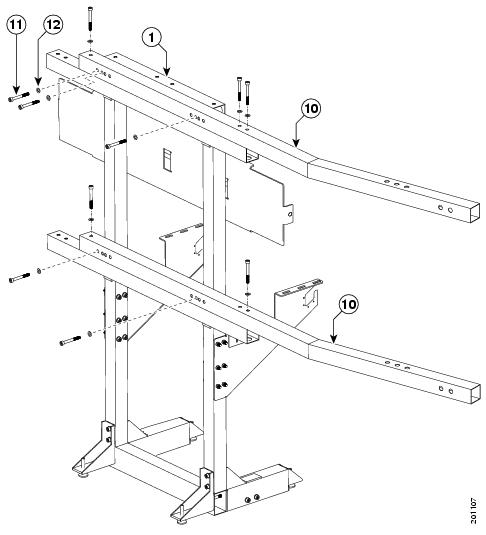
Step 7
Figure 2-7 Upper and Lower Support crossbars
Tip
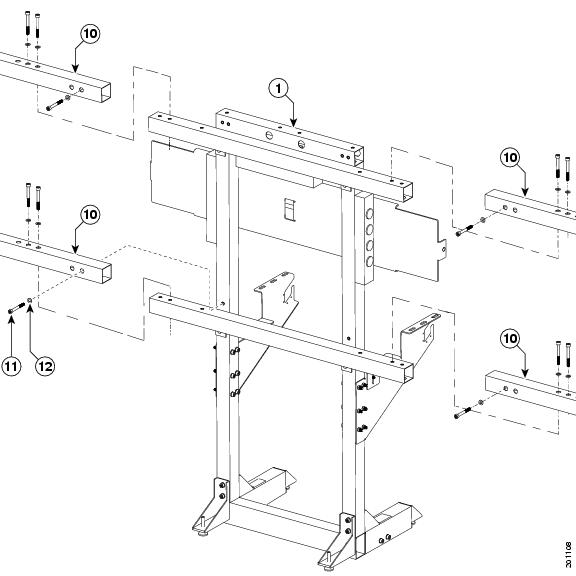
Step 8
Figure 2-8 Upper and Lower Support crossbars
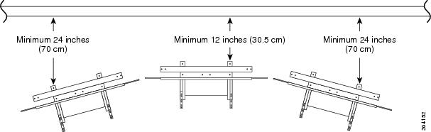
Step 9
Figure 2-9 Positioning the Display Structures