Feedback Feedback
|
Table Of Contents
Release Notes for Cisco MGX Route Processor Module (RPM-XF) for MGX 8850 Release 3.0.00 (PXM45)
Features Not Supported in This Release
RPM-XF Limitations and Restrictions
RPM-XF auto_config File Management
Known Anomalies for RPM-XF Platform Software and Service Module Firmware
RPM-XF Boot File and Firmware File Names and Sizes
Cisco IOS Release Compatibility Information
Using XModem to Download Flash to RPM-XF Cards
Obtaining Technical Assistance
Release Notes for Cisco MGX Route Processor Module (RPM-XF) for MGX 8850 Release 3.0.00 (PXM45)
Contents
About These Release Notes
Cisco documentation and additional literature are available in a CD-ROM package, which ships with your product. The Documentation CD-ROM, a member of the Cisco Connection Family, is updated monthly. Therefore, it might be more current than printed documentation. To order additional copies of the Documentation CD-ROM, contact your local sales representative or call customer service. The CD-ROM package is available as a single package or as an annual subscription.
Note that for Release 3, the user documentation (command reference, overview, and installation and configuration guides) use the MGX Release 3 and Cisco IOS documents in addition to this release note.
Product documentation for MGX 8850 is available at the following URL:
http://www.cisco.com/univercd/cc/td/doc/product/wanbu/8850r30/index.htm
http://www.cisco.com/univercd/cc/td/doc/product/wanbu/8850r30/rpm/index.htmFeatures
The MGX RPM-XF is a next-generation, high performance model of the RPM for the MGX 8850 platform, using PXM45 processor modules. It is a router module based on an RM7000A MIPS processing engine that fits into slots 1-6 and slots 9-14 in MGX 8850.
The RPM-XF hardware provides forwarding technology for packet switching capabilities in excess of 2-million pps. The forwarding engine is packet based and is interfaced to the midplane of the system through a combination of switch interface technologies. For more information on the RPM-XF, refer to the Cisco MGX Route Processor Module (RPM-XF) Installation and Configuration Guide, Release 3.
RPM-XF Redundancy Support
RPM-XF 1:N redundancy is used to switch configuration and traffic from one RPM-XF module to another module. Route processing continues with minimal traffic loss even if an RPM-XF fails and there is no operator or direct access to swap the failed card or fix the problem. Currently we support RPM-XF warm redundancy, which ensures Layer 2 state restoration. Layer 3 state is restored via convergence.
The main benefits are:
•
An RPM-XF card with hardware problems can be fixed while the redundant standby card takes over its functionality.
•
•
•
•
The following are the general guidelines for redundancy on the RPM--XF:
•
•
•
•
•
•
•
•
Features Not Supported in This Release
The following features are not supported in this release.
•
•
•
•
•
•
•
•
Network Management Features
Network management features are detailed in the CWM Release 11.0 Release Notes at: http://cisco.com/univercd/cc/td/doc/product/wanbu/svplus/index.htm
SNMP MIB
SNMP MGX Release 3 MIB are provided with the delivery of this release. The MIB is in standard ASN.1 format and is located in the same directory within the release bundle on CCO. These files may be compiled with most standards-based MIB compilers. The tar file for MIB contains the file that contains the MIB release notes. This contains only MGX MIBS.
Cisco IOS MIBS are not part of this bundle. They are part of 12.2(8)T4 CCO release.
RPM-XF Limitations and Restrictions
The RPM-XF limitations and restrictions that apply to this release are as follows:
•
•
•
•
•
•
•
•
•
•
•
•
•
•
•
•
•
•
•
•
•
•
•
•
The performance limits supported in this release are the following:
•
•
•
•
•
•
•
•
•
•
•
•
•
•
•
For more RPM-XF performance details, contact your sales representative.
Notes and Cautions
The following notes and cautions should be reviewed before using this release.
•
•
•
•
•
•
•
•
•
–
–
•
RPM-XF auto_config File Management
The RPM-XF auto_config_slot# file stores the configuration for the RPM-XF card. The slot# portion of the name should be set to the logical slot number that corresponds to the RPM-XF card. This file can be stored in bootflash or in the E:RPM directory on the PXM45 hard disk. The configuration is also stored in NVRAM using the name startup-config.
When the RPM-XF card is inserted or rebooted, it searches for the configuration file in the following sequence:
1.
2.
3.
Note
Card Management
The following card management notes and cautions should be reviewed before using this release.
•
•
•
Another workaround is to enter cont on the ROMMON within 2 minutes of going into ROMMON state. This will bring the card to its original stable state.
Note
•
Note
RPM-XF Bootflash Precautions
The RPM-XF bootflash is used to store boot image, configuration and run- time files. Erasing the boot image from the Flash will cause the card to not boot.
The RPM-XF boot image, which comes loaded on the Flash, will work for all RPM-XF IOS images. Therefore, there is no reason to delete or move the factory installed boot image.
In order to avoid any unnecessary failures that would require card servicing, do the following:
•
•
•
As long as the boot file remains intact in the first position on the flash, the RPM-XF will boot successfully.
If the bootflash is corrupted, use the tftpdnld procedure described in the Cisco MGX Route Processor Module (RPM-XF) Installation and Configuration Guide or xmodem procedure described in "Using XModem to Download Flash to RPM-XF Cards" later is this document to download a new boot image.
Known Anomalies for RPM-XF Platform Software and Service Module Firmware
The following is the list of known anomalies in the RPM service module firmware and software for this release. Included with each is a brief discussion of the problem. A more in-depth discussion is available in the Release Note enclosure of the problem record in Bug Navigator.
Compatibility Notes
RPM-XF Boot File and Firmware File Names and Sizes
The following table displays the RPM-XF boot and firmware file names and sizes for this release.
Table 1 RPM Boot and Firmware File Names and Sizes
rpmxf-boot-mz.122-8.YP
2650352
rpmxf-p12-mz.122-8.YP
7445884
RPM-XF Compatibility Matrix
MGX RPM-XF Hardware
Table 2 shows the front card and back card compatibility for the RPM-XF hardware supported in this release. The table lists the card model/ name, part numbers, the minimum version and the minimum revisions of each card supported. Note that there may be more than one 800 level part numbers for the same front cards. The minimum version is identified by the last 2 digits of the 800 level numbers.
Table 3 SFP Compatibility Matrix for MGX-1GE
Min. VersionMGX-GE-SX
MGX-GE-LHLX
MGX-GE-ZX
30-1301-01
30-1299-01
10-1439-01
A0
A0
A0
Cisco IOS Release Compatibility Information
All IOS firmware can be downloaded from CCO from the following location:
http://www.cisco.com/kobayashi/sw-center/sw-ios.shtml
Using XModem to Download Flash to RPM-XF Cards
Use the xmodem feature to download the flash to an RPM-XF card. During this process, the card should be connected to a target machine through HyperTerminal with settings of 9600, n, 8, and 1.
Step 1
rommon 1> privYou now have access to the full set of monitor commands. Warning: some commands will allow you to destroy your configuration and/or system images and could render the machine unbootable.Step 2
rommon 2 > xmodemusage: xmodem [-cys]-c CRC-16-y ymodem-batch protocol-s<speed> Set speed of download, where speed may be1200|2400|4800|9600|19200|38400rommon 3 >The command line options for xmodem are as follows:
Note
Note
For example:
rommon 4> xmodem -cys 38400Do not start sending the image yet...Invoke this application for disaster recovery. Do you wish tocontinue? y/n [n]: yNote, if the console port is attached to a modem, both theconsole port and the modem must be operating at the same baudrate. Use console speed 38400 bps for download [confirm]Step 3
Note
The console will display the following message:
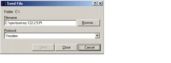
Download will be performed at 38400. Make sure your terminalemulator is set to this speed before sending file. Ready toreceive file ...Step 4
In the Filename box, browse and choose the image file to be downloaded. Also since we used the "y" option while invoking the xmodem, set the transfer protocol to ymodem or use Xmodem protocol by not specifying the -y option on the command line.
The transfer screen comes up and transfer starts. (The transfer may not start immediately; wait for some time and it should start.)
After the transfer is completed (it should typically take about 10-15 minutes), the following messages are displayed on HyperTerminal console:
Returning console speed to 9600.Please reset your terminal emulator to this speed...Step 5
Usually, due to time lag between changing HyperTerminal speed back to 9600, you might see a bunch of garbage. To avoid this, disconnect and reconnect the HyperTerminal to get the console back again.
The system will reset itself from here and will boot with new software image.
Related Documentation
Cisco documentation and additional literature are available in a CD-ROM package, which ships with your product. The Documentation CD-ROM, a member of the Cisco Connection Family, is updated monthly. Therefore, it might be more current than printed documentation. To order additional copies of the Documentation CD-ROM, contact your local sales representative or call customer service. The CD-ROM package is available as a single package or as an annual subscription.
Note that for Release 3, the user documentation (command reference, overview, and installation and configuration guides) use the MGX Release 3 and Cisco IOS documents in addition to this release note.
Product documentation for MGX 8850 is available at the following URL:
http://www.cisco.com/univercd/cc/td/doc/product/wanbu/8850r30/index.htm
http://www.cisco.com/univercd/cc/td/doc/product/wanbu/8850r30/rpm/index.htmObtaining Documentation
The following sections explain how to obtain documentation from Cisco Systems.
World Wide Web
You can access the most current Cisco documentation on the World Wide Web at the following URL:
Translated documentation is available at the following URL:
http://www.cisco.com/public/countries_languages.shtml
Documentation CD-ROM
Cisco documentation and additional literature are available in a Cisco Documentation CD-ROM package, which is shipped with your product. The Documentation CD-ROM is updated monthly and may be more current than printed documentation. The CD-ROM package is available as a single unit or through an annual subscription.
Ordering Documentation
Cisco documentation is available in the following ways:
•
http://www.cisco.com/cgi-bin/order/order_root.pl
•
http://www.cisco.com/go/subscription
•
Documentation Feedback
If you are reading Cisco product documentation on Cisco.com, you can submit technical comments electronically. Click Leave Feedback at the bottom of the Cisco Documentation home page. After you complete the form, print it out and fax it to Cisco at 408 527-0730.
You can e-mail your comments to bug-doc@cisco.com.
To submit your comments by mail, use the response card behind the front cover of your document, or write to the following address:
Cisco Systems
Attn: Document Resource Connection
170 West Tasman Drive
San Jose, CA 95134-9883We appreciate your comments.
Obtaining Technical Assistance
Cisco provides Cisco.com as a starting point for all technical assistance. Customers and partners can obtain documentation, troubleshooting tips, and sample configurations from online tools by using the Cisco Technical Assistance Center (TAC) Web Site. Cisco.com registered users have complete access to the technical support resources on the Cisco TAC Web Site.
Cisco.com
Cisco.com is the foundation of a suite of interactive, networked services that provides immediate, open access to Cisco information, networking solutions, services, programs, and resources at any time, from anywhere in the world.
Cisco.com is a highly integrated Internet application and a powerful, easy-to-use tool that provides a broad range of features and services to help you to
•
•
•
•
•
You can self-register on Cisco.com to obtain customized information and service. To access Cisco.com, go to the following URL:
Technical Assistance Center
The Cisco TAC is available to all customers who need technical assistance with a Cisco product, technology, or solution. Two types of support are available through the Cisco TAC: the Cisco TAC Web Site and the Cisco TAC Escalation Center.
Inquiries to Cisco TAC are categorized according to the urgency of the issue:
•
•
•
•
Which Cisco TAC resource you choose is based on the priority of the problem and the conditions of service contracts, when applicable.
Cisco TAC Web Site
The Cisco TAC Web Site allows you to resolve P3 and P4 issues yourself, saving both cost and time. The site provides around-the-clock access to online tools, knowledge bases, and software. To access the Cisco TAC Web Site, go to the following URL:
All customers, partners, and resellers who have a valid Cisco services contract have complete access to the technical support resources on the Cisco TAC Web Site. The Cisco TAC Web Site requires a Cisco.com login ID and password. If you have a valid service contract but do not have a login ID or password, go to the following URL to register:
http://www.cisco.com/register/
If you cannot resolve your technical issues by using the Cisco TAC Web Site, and you are a Cisco.com registered user, you can open a case online by using the TAC Case Open tool at the following URL:
http://www.cisco.com/tac/caseopen
If you have Internet access, it is recommended that you open P3 and P4 cases through the Cisco TAC Web Site.
Cisco TAC Escalation Center
The Cisco TAC Escalation Center addresses issues that are classified as priority level 1 or priority level 2; these classifications are assigned when severe network degradation significantly impacts business operations. When you contact the TAC Escalation Center with a P1 or P2 problem, a Cisco TAC engineer will automatically open a case.
To obtain a directory of toll-free Cisco TAC telephone numbers for your country, go to the following URL:
http://www.cisco.com/warp/public/687/Directory/DirTAC.shtml
Before calling, please check with your network operations center to determine the level of Cisco support services to which your company is entitled; for example, SMARTnet, SMARTnet Onsite, or Network Supported Accounts (NSA). In addition, please have available your service agreement number and your product serial number.
This document is to be used in conjunction with the Cisco WAN Switching MGX 8850 Release 3 publications.
CCIP, the Cisco Powered Network mark, the Cisco Systems Verified logo, Cisco Unity, Follow Me Browsing, FormShare, Internet Quotient, iQ Breakthrough, iQ Expertise, iQ FastTrack, the iQ Logo, iQ Net Readiness Scorecard, Networking Academy, ScriptShare, SMARTnet, TransPath, and Voice LAN are trademarks of Cisco Systems, Inc.; Changing the Way We Work, Live, Play, and Learn, Discover All That's Possible, The Fastest Way to Increase Your Internet Quotient, and iQuick Study are service marks of Cisco Systems, Inc.; and Aironet, ASIST, BPX, Catalyst, CCDA, CCDP, CCIE, CCNA, CCNP, Cisco, the Cisco Certified Internetwork Expert logo, Cisco IOS, the Cisco IOS logo, Cisco Press, Cisco Systems, Cisco Systems Capital, the Cisco Systems logo, Empowering the Internet Generation, Enterprise/Solver, EtherChannel, EtherSwitch, Fast Step, GigaStack, IOS, IP/TV, LightStream, MGX, MICA, the Networkers logo, Network Registrar, Packet, PIX, Post-Routing, Pre-Routing, RateMUX, Registrar, SlideCast, StrataView Plus, Stratm, SwitchProbe, TeleRouter, and VCO are registered trademarks of Cisco Systems, Inc. and/or its affiliates in the U.S. and certain other countries.
All other trademarks mentioned in this document or Web site are the property of their respective owners. The use of the word partner does not imply a partnership relationship between Cisco and any other company. (0203R)
Copyright © 2002, Cisco Systems, Inc.
All rights reserved.