|
Table Of Contents
New Features and Enhancements in Release 4.0.00
Preferred Routes for PNNI Multipeer Group Networks
Point-to-Multipoint SVC/SPVC Support
Increased Number of Signaling Interfaces
PXM1E-Related Hardware (the PXM1E-8-155 card)
Modular Transceiver Support in the New 8-port OC3/STM1 Back Card
UNI connection support in PXM1E-16-T1E1
Cell Bus Service Module Support
Virtual Trunks Support in PXM1E
AXSM-E as Upstream to Feeder Nodes
Cell Bus Service Modules on PXM45
Service Class Template (SCT) File Information
Software/Firmware Interoperability Matrix
MGX and RPM Software Version Compatibility Matrix
New Hardware in Release 4.0.00
MGX 8850 (PXM45) Product IDs and Card Types
MGX 8850 (PXM1E) Product IDs and Card Types
MGX 8830 Product IDs and Card Types
MGX 8950 Product IDs and Card Types
New and Changed PXM45 and PXM1E Commands
AXSM-4-2488-XG Channelization Commands
Limitations, Restrictions, and Notes for 4.0.00
Point to Multipoint SVC/SPVC Support
Narrow Band Service Modules and RPM-PR
AXSM-E as Upstream to Feeder Nodes
Maximum Threshold Accuracy for PXM45 and PXM1E
Controller Card Mastership Sanity Verification
Serial Bus Path Fault Isolation
Cell Bus Path Fault Isolation and Recovery
Non-native Controller Front Card and PXM-HD Card
Simple Network Timing Protocol (SNTP)
AXSM-32-T1E1-E and PXM1E-16-T1E1
Other Limitations and Restrictions
Clearing the Configuration on Redundant PXM45 and PXM1E Cards
Limitations and Restrictions for 2.1.x
General Limitations, Restrictions, and Notes
Limitations for rteopt via parallel links
Installation and Upgrade Procedures
Cisco MGX 8850 (PXM45) Multiservice Switch Release 4
Cisco MGX 8850 (PXM1E) Multiservice Switch Release 4
Cisco MGX 8950 Multiservice Service Release 4
Cisco MGX 8830 Multiservice Switch Release 4
Cisco WAN Switching Software Release 9.4
MGX 8850 (PXM1) Edge Concentrator Release 1.2.20
MGX 8250 Edge Concentrator Release 1.2.20
MGX 8230 Edge Concentrator Release 1.2.20
How to Find Multiservice Switch Customer Documents Online
If the Part Number is Not Known
Documentation on the World Wide Web
Contacting TAC by Using the Cisco TAC Website
MGX 8850, MGX 8830, and MGX 8950 Anomalies
Known Anomalies in Release 4.0.00
Known Route Processor Module or MPLS Anomalies
Release Notes for Cisco MGX 8850 (PXM1E/PXM45), Cisco MGX 8950, and Cisco MGX 8830, Software Version 4.0.00
Contents
These release notes are part OL-3245-01 Rev. D0, January 21, 2004.
About Release 4.0.00
These release notes describe the system requirements, new features, and limitations that apply to Release 4.0.00 of the MGX 8850 and the new MGX 8830 multiservice switch. These notes also contain Cisco support information.
MGX Release 4.0.00 helps fulfill the original MGX feature expectation of direct cell bus service module (CBSM) support on both feeder and routing nodes, while positioning the high end of the product line for next-generation broadband networking.
With this release, most of the Narrow Band Service Modules currently supported on the MGX 8850 (PXM1) are now supported on the MGX 8830 and MGX 8850 (PXM1E) and MGX 8850 (PXM45). This brings to service providers unparalleled flexibility in the way they choose to terminate service access in their networks.
MGX Release 4.0.00 also brings to the industry the first true next-generation multiservice platform with a new set of Service Modules that put the MGX 8950 switch's powerful backplane throughput at the fingertips of network architects. An MGX 8950 chassis can now be configured with the highest broadband port density available in the industry and up to 10G bandwidth available from each of the 12 Service Module slots.
In support of this unprecedented multiservice throughput, a slew of PNNI features are also being released to facilitate continued expansion of MGX networks.
These release notes complement the technical manuals listed in the "Related Documentation" section.
Note Release notes for MGX 8950, Release 4.0.00, are combined with these release notes.
Type of Release
Release 4.0.00 is a software and hardware release for all MGX switches:
•MGX 8830 PNNI routing switch
•MGX 8850 (PXM1E)
•MGX 8850 (PXM45)
•MGX 8950.
Locating Software Updates
This is the location for the MGX 8850 and MGX 8830 4.0.00 software:
•http://www.cisco.com/kobayashi/sw-center/wan/wan-planner.shtml
Note Please contact your account representative to obtain Release 4.0.00 for MGX 8950.
New Features and Enhancements in Release 4.0.00
Note Starting with this release, you will see reference to cell bus service modules (CBSMs). CBSMs were formerly called narrow band service modules (NBSMs). As the MGX product line has grown, the narrow band distinction is no longer appropriate. CBSMs use the MGX cell bus for customer traffic instead of the serial bus used by cards such as AXSM and FRSM-12-T3E3.
Refer to the "Acronyms" section for definitions of acronyms used in these release notes.Release 4.0.00 contains the following new features:
•Closed User Groups (CUG)
•Preferred routes for PNNI Multipeer Group Networks
•Point to Multipoint SVC/SPVC support (P2MP)
•Increased number of Signaling Interfaces
•Virtual trunks support in PXM1E
•Virtual UNI support in PXM1E
•AXSM-E and PXM1E as Upstream to Feeder Nodes and IGX Feeder to MGX 8850
•Narrow Band on PXM45
•AXSM-32-T1E1-E UNI with IMA
•PXM1E-16-T1E1 UNI with IMA
•PXM45/C
•AXSM-1-9953-XG
•AXSM-4-2488-XG
Table 1 lists which switch supports which new feature.
Table 1 MGX Release 4.0.00 Feature Support by Switch
New Release 4.0.00 Feature MGX 8850 PXM45(A) MGX 8850 PXM45/B MGX 8850PXM45/C MGX 8950 MGX 8850 (PXM1E) MGX 8830Closed User Groups (CUG)
NO
YES
YES
YES
YES
YES
Preferred routes for PNNI Multipeer Group Networks
YES
YES
YES
YES
YES
YES
Point to Multipoint SVC/SPVC support (P2MP)
NO
YES
YES
YES
YES
NO
Increased number of Signaling Interfaces
NO
YES
YES
YES
N/A
N/A
Virtual trunks support in PXM1E
NO
NO
NO
NO
YES
YES
Virtual UNI support in PXM1E
N/A
N/A
N/A
NO
YES
YES
PXM1E as Upstream to Feeder Nodes
N/A
N/A
N/A
NO
YES
YES
AXSM-E Upstream to Feeder Nodes
YES
YES
YES
NO
NO
NO
Narrow Band on PXM451
NO
YES
YES
NO
NO
NO
Additional Narrow Band on PXM1E
N/A
N/A
N/A
NO
YES
YES
AXSM-32-T1E1-E UNI with IMA
NO
NO
NO
NO
N/A
N/A
PXM1E-16-T1E1 UNI with IMA
N/A
N/A
N/A
NO
YES
YES
PXM1E-8-155
N/A
N/A
N/A
N/A
YES
YES
PXM45/C
NO
NO
YES
YES
NO
NO
AXSM-1-9953-XG
NO
NO
NO
YES
NO
NO
AXSM-4-2488-XG
NO
NO
NO
YES
NO
NO
Closed User Groups
The Closed User Groups (CUG) supplementary service enables network users to form groups, to and from which access is restricted. A network user may be associated with one CUG, multiple CUGs, or no CUG. Members of a specific CUG can communicate typically among themselves, but in general not with network users outside of the CUG. Specific network users can have additional restrictions preventing them from originating calls to, or receiving calls from, network users of the same CUG (Outgoing Calls Blocked or Incoming Calls Blocked). In addition, a network user can be further restricted in originating calls to, or receiving calls from, network users outside of any CUG membership defined for the network user (Outgoing Access or Incoming Access.).
The feature is based on the ITU-T Q.2955.1 recommendation.
Platforms
Closed User Groups is supported on:
•MGX 8850 (PXM45)
•MGX 8850 (PXM1E)
•MGX 8830
•MGX 8950
References
ITU-T Q.2955.1
Preferred Routes for PNNI Multipeer Group Networks
Preferred routing of connections provides the network operator a means of bypassing the PNNI route selection, and configuring a specific path through the network which a connection will follow. Preferred routes can be configured as either Preferred or Directed routes. A Preferred route is one which will follow the configured path if available, but will revert to a PNNI-selected route if the preferred route is not available. A Directed route is one which will follow only the configured path; if the configured path is not available, the connection will remain unrouted.
Preferred routes can be specified for SPVCs from source switch to the destination switch end-to-end using CLI or SNMP. The end-to-end preferred route for connections can span across multiple peer groups. The implementation is based on PNNI 1.1 specification.
Platforms
This feature is supported on:
•MGX 8850 (PXM45)
•MGX 8850 (PXM1E)
•MGX 8830
•MGX 8950
References
PNNI 1.1
Point-to-Multipoint SVC/SPVC Support
The SVC/SPVC point-to-multipoint (P2MP) feature offers the ability for one root SVC/SPVC connection to establish a simple tree topology to one or more leaf connections. The data traffic is uni-directional from root multicast to all leaves, i.e., what is sent from the root data channel is received by all leaves. From the root, leaves can be added to the connection using SETUP/ADD_PARTY signaling messages. Point-to-multipoint is a mandatory feature described in UNI 3.0, UNI3.1 and UNI4.0 specs. The implementation is compliant with in Q2971.
Platforms
This feature is supported on:
•MGX 8850 (PXM45)
•AXSM/B on MGX 8950
•AXSM/B on MGX 8850 (PXM45)
Note AXSM/B support is limited due to the capability of the hardware. P2MP connections and throughput are limited.
References
UNI 3.0, UNI3.1, UNI4.0, Q2971
Increased Number of Signaling Interfaces
Support for up to 192 PNNI routing/signaling interfaces on MGX 8850 (PXM45/B and PXM45/C). Prior to this release, the platform supports only 99 signaling interfaces. The features enables increased signaling interfaces for interconnecting with other switches or DSLAMs.
Platforms
This feature is supported on:
•MGX 8850 (PXM45)
•MGX 8950
PXM1E-Related Hardware (the PXM1E-8-155 card)
•8-port OC3/STM1and MCC-8-155
•Continues to support existing PXM1 features
•PXM1E 8-port OC3/STM1 will require the UI-S3/B back card
•PXM1E-8-155, new 8-port OC3/STM1 back card with the SFP and MCC-8-155 support.
Redundancy Support
The PXM1E PNNI Controller offers redundancy, offer hitless operation, and Y-Redundancy (1:1) will be supported in PXM1E for the 155 interface.
Service Modules will have 1:N redundancy and 1:1 redundancy as supported by the individual service modules
Automatic Protection Switching Support
Automatic Protection Switching (APS) 1:1 and1+1 for both the Bellcore GR-253 and ITU-T G.783 Annex-A and Annex-B standards will be supported for the OC3 and STM1 interfaces. The MGX-8850-APS-CON plane is required for APS functionality.
Modular Transceiver Support in the New 8-port OC3/STM1 Back Card
The PXM1E will support a single universal back card capable of supporting single-mode and multi-mode fiber connectors for the different reaches in OC3 and STM1.
External field-replaceable transceivers for SMF-IR, SMF-LR and MMF, purchased by the customer, will be supported.
UNI connection support in PXM1E-16-T1E1
In a previous software release (3.0.10), the PXM1E-16-T1E1 card provided support for IMA trunking. In the MGX 4.0.00 release, the same card will support both native ATM UNI and IMA UNI endpoints. Sixteen T1/E1 ports can be mixed and matched for either native UNI or NNI ports and IMA UNI or NNI ports.
ATM Routing in PXM1E
The PXM1E-based switches support the ATM Forum standard PNNI routing/signaling based on the same baseline used for MGX 8850 (PXM45) and BPX/SES systems. It can be a peer to the PXM45-based switches in the single peer group and participate in multipeer groups.
Connection Management
Supports different types of connections—SVC, SVP, S-PVC, and S-PVP. UNI 3.X/4.0 signaling and ILMI are used to setup SVCs and SVPs.
PXM1E will support 13,500 local switching connections and 27,000 routed connections.
Cell Bus Service Module Support
A cell bus service module is an MGX service module that uses the MGX cell bus to transport customer traffic between that service module and other services modules or PXM uplinks. Traditionally, the CBSMs were called narrow band service modules (NBSMs).
For a summary of service modules supported in MGX 8830 and MGX 8850 (PXM1E), please refer to Table 2
Virtual Trunks Support in PXM1E
Virtual trunks will be supported in the PXM1E ports. A maximum of 31 (physical and virtual) trunks can be supported in a PXM1E card. The feature will be supported in 4-port OC3/STM1, 8-port T3/E3, 8-port OC3/STM1, 16- port T1/E1 and the combo PXM1E cards. SVC, SPVC and SPVP connections can be routed over the virtual trunks.Virtual trunks can originate and terminate between PXM1E, AXSM/A, AXSM/B, AXSM-XG and AXSM-E cards.
Virtual UNI Support in PXM1E
A new port type called Virtual UNI (VUNI) and Enhanced Virtual UNI(EVUNI) is defined in addition to the already defined port types UNI, NNI, VNNI (Virtual Trunk). This feature benefits both the MPLS and PNNI control plane.
Feeder Trunk support in PXM1E
PXM1E ports can accept feeder trunks in any port. IGX 8400, MGX 8230, MGX 8250 and MGX 8850 (PXM1) can be added as feeders to MGX 8830 and MGX 8850 (PXM1E).
PXM1E Diagnostics
Both HMM and online diagnostics report alarms in the Hardware Alarm category under the card alarms.
•HMM reports alarms for all devices when error thresholds are crossed. Further information can be obtained via the CLI dspdeverr <device>. This CLI will have to be issued for each device to ensure that all relevant errors have been observed. The alarm raised by the specific instance of the device (for example, QE1210 - 0 or 1) will also be available in the dspdeverr CLI.
•The CLI dspdiagerr online indicates whether there is error reported by online diagnostics. Further information regarding the error can be obtained from the event logs via a filter using CLI dsplog -mod PXMD.
POST test results printed to the console immediately after execution may display failures. These may be due to tests being attempted for devices not present on the particular PXM1E-board (such as the second ATM policing device on the PXM1E-4-155). The tests are based purely on device offsets and can display spurious results. To confirm/rule-out real and relevant tests, please use the following examples:
Example 1 PXM1E-4-155: ATM policing device 2 and framers 2 and 4 do not exist: Following shows all relevant test cases passed. Although framers 2 and 4 show passed below, those two cases must be ignored.
Power On Self Test Results
Test Name Result Description
BRAM Checksum PASS
QE Ram PASS
CBC Ram PASS
Ethernet Reg PASS
PCI-IDE Reg PASS
Clock Mux PASS
Framer 1 Access PASS
Framer 2 Access PASS
Framer 3 Access PASS
Framer 4 Access PASS
ATLAS 1 Ram PASS
ATLAS 2 Ram FAIL Ingress SRAM: Pattern Not Matched
Hard Disk Access PASS
Example 2 PXM1E-8-T3E3: ATM policing device 2 and framers 3 and 4 do not exist: Following shows all relevant test cases passed.
Power On Self Test Results
Test Name Result Description
BRAM Checksum PASS
QE Ram PASS
CBC Ram PASS
Ethernet Reg PASS
PCI-IDE Reg PASS
Clock Mux PASS
Framer 1 Access PASS
Framer 2 Access PASS
Framer 3 Access FAIL Framer 3 Access 1 Fail
Framer 4 Access FAIL Framer 4 Access 1 Fail
ATLAS 1 Ram PASS
ATLAS 2 Ram FAIL Ingress SRAM: Pattern Not Matched
Hard Disk Access PASS
Example 3 PXM1E-T3E3-155: Following shows all relevant test cases passed.
Power On Self Test Results
Test Name Result Description
BRAM Checksum PASS
QE Ram PASS
CBC Ram PASS
Ethernet Reg PASS
PCI-IDE Reg PASS
Clock Mux PASS
Framer 1 Access PASS
Framer 2 Access PASS
Framer 3 Access PASS
Framer 4 Access PASS
ATLAS 1 Ram PASS
ATLAS 2 Ram PASS
Hard Disk Access PASS
Example 4 PXM1E-8-155: Following shows all relevant test cases passed. For the 8OC3, the ethernet controller test is not done, since the controller is part of the system controller which is not tested in this release.
Power On Self Test Results
Test Name Result Description
BRAM Checksum PASS
QE Ram PASS
CBC Ram PASS
Ethernet Reg NOT_DONE Ethernet Controller Test Not Required.
PCI-IDE Reg PASS
Clock Mux PASS
Framer 1 Access PASS
Framer 2 Access PASS
Framer 3 Access PASS
Framer 4 Access PASS
ATLAS 1 Ram PASS
ATLAS 2 Ram PASS
Hard Disk Access PASS
Example 5 PXM1E-16-T1E1: ATM policing device 2 and framers 1,2,3 and 4 do not exist: Following shows all relevant test cases passed.
Power On Self Test Results
Test Name Result Description
BRAM Checksum PASS
QE Ram PASS
CBC Ram PASS
Ethernet Reg PASS
PCI-IDE Reg PASS
Clock Mux PASS
Framer 1 Access FAIL Framer 1 Access 1 Fail
Framer 2 Access FAIL Framer 2 Access 1 Fail
Framer 3 Access FAIL Framer 3 Access 1 Fail
Framer 4 Access FAIL Framer 4 Access 1 Fail
ATLAS 1 Ram PASS
ATLAS 2 Ram FAIL Ingress SRAM: Pattern Not Matched
Hard Disk Access PASS
AXSM-E as Upstream to Feeder Nodes
Previously supported only with AXSM and AXSM/B cards, the feeder upstream capability will now be supported using the AXSM-E card as well. This feature enables PXM1 and IGX 8400 feeder nodes to be directly connected to the AXSM-E cards on the PXM45 nodes.
Platform
•MGX 8850 (PXM45)
Cell Bus Service Modules on PXM45
This feature allows key Cell Bus Service Modules to be supported on the MGX 8850 (PXM45). Where necessary, these cards can be used in conjunction with the SRME or SRM-3T3/C Service Resource Module for distribution and redundancy purposes. Please see Table 2 for details.
Platform
•MGX 8850 (PXM45)
Note Support for these Service Modules is already available on all PXM1 and PXM1E platforms.
Table 2 Cell Bus Service Modules (CBSMs) Supported in Release 4.0.00
Note 1. For better performance, we encourage you to use MGX-CESM-8T1/B on nodes with PXM45/B and PXM45/C processor/ controller cards.
Note 2. APS is not supported for SRME on PXM45(A).
AXSM-32-T1E1-E UNI with IMA
This feature allows the AXSM-32-T1E1-E to support the IMA capability on a UNI, VUNI, and EVUNI interface. This is in addition to the IMA trunking feature already supported in a previous release.
Platforms
•MGX 8850 (PXM45)
PXM45/C
The PXM45/C is a combination ATM switching fabric/processor card. The switching fabric provides 45 Gbps of non-blocking switching capacity, while the processor provides the control plane that delivers ATM networking software, diagnostics, and performance monitoring.
Platforms
•MGX 8850 (PXM45)
•MGX 8950
AXSM-1-9953-XG
The AXSM-1-9953-XG ATM Switch Service Module is a high-density, double-height Service Module for use in the Cisco MGX 8950 Next Generation Multiservice Switch in combination with the high-capacity PXM45 processor switching module and the XM-60 switching module, to deliver OC-192c/STM-64 trunk connectivity.
Up to 12 AXSM-XG service modules can be accommodated in the Cisco MGX 8950.
Platforms
•MGX 8950
AXSM-4-2488-XG
The AXSM-4-2488-XG ATM Switch Service Module is a Quad OC-48/STM-16, double-height service module for use in the Cisco MGX 8950 Next Generation Multiservice Switch. Used in combination with the high-capacity PXM45 processor and the XM-60 switching module it delivers high density connectivity of 4 interfaces of OC-48/STM-16, either in a clear-channel format or as channelized to OC-12/STM-4, OC-3/STM-1, and DS-3.
Up to 12 AXSM-4-2488-XG service modules can reside in the Cisco MGX 8950, to provide up to 48 OC-48/STM-16 interfaces to support service providers that require both high bandwidth and highest network availability. When used in the channelized mode, each service module can carry alternatively up to 64 DS-3 channels, 64 OC-3/STM-1 channels, 16 OC-12/STM-4 channels, or any combination of these 3 types adding up to 64 channels.
Platforms
•MGX 8950
Frame Discard Feature
New developments have occurred in the CLI for the Frame Discard feature in connection provisioning. Starting with releases 3.0.23 and 4.0.10, two types of frame discard became available. For a detailed explanation, see the addcon or cnfcon description in either the Cisco MGX 8830, MGX 8850 (PXM45 and PXM1E), and Cisco MGX 8950 Command Reference (Release 3 or 4) or the Cisco ATM Services (AXSM) Software Configuration Guide and Command Reference for MGX Switches (Release 3 or 4). Also see the Note in the Installation and Upgrade section of these release notes.
Enhancements
The product enhancement requests (PERs) in Table 3 were introduced in Release 4.0.00.
Service Class Template (SCT) File Information
This section contains SCT file information for Release 4.0.00.
PXM1E
The Service Class Template (SCT) bundle in Release 4.0.00 includes updates:
•PXM1E_SCT.PORT.5
•PXM1E_SCT.PORT.6
The default SCTs provided with Release 4.0.00 are as follows:
•SCT 5 - policing enabled. In general, this is for use on UNI ports.
•SCT 6 - policing disabled. In general, this is for use on NNI ports.
PXM1E_SCT.PORT.5.V1:Check sum is = 0x18a4fdad= 413466029
PXM1E_SCT.PORT.6.V1:Check sum is = 0x2cb30eb7= 749932215
PXM1E does not support CARD SCT. See CSCdx55759 for details.
ABR VSVD parameters are not supported due to hardware limitation.
The above PXM1E SCT files apply to MGX 8850 (PXM1E) and MGX 8830.
The Service Class Template (SCT) bundle in Release 4.0.00 includes updates:
•AXSME_SCT.CARD.5
•AXSME_SCT.PORT.5
•AXSME_SCT.PORT.6
AXSM and AXSM/B
•SCT 2 - policing enabled, PNNI
•SCT 3 - policing disabled, PNNI
•SCT 4 - policing enabled, MPLS and PNNI
•SCT 5 - policing disabled, MPLS and PNNI
The check sum for the SCT files are as follows
•AXSM_SCT.PORT.2.V1:Check sum is = 0x78ccfb22= 2026699554
•AXSM_SCT.PORT.3.V1:Check sum is = 0x987919a7= 2558073255
•AXSM_SCT.PORT.4.V1:Check sum is = 0x775bfaa2= 2002516642
•AXSM_SCT.PORT.5.V1:Check sum is = 0xe84c696a= 3897321834
•AXSM_SCT.CARD.2.V1:Check sum is = 0x78ccfb22= 2026699554
•AXSM_SCT.CARD.3.V1:Check sum is = 0x987919a7= 2558073255
•AXSM_SCT.CARD.4.V1:Check sum is = 0x775bfaa2= 2002516642
•AXSM_SCT.CARD.5.V1:Check sum is = 0xe84c696a= 3897321834
A user can do dspsctchksum <filename> to confirm that the checksum of the Cisco-released SCT file and the file on the node match.
AXSM-E
These are the new AXSM-E SCT files:
•SCT 4 - policing enabled for PNNI, disabled for MPLS
•SCT 5 - policing enabled for PNNI, disabled for MPLS
•SCT 6 - Policing disabled, used for trunks
•SCT 52 - Policing enabled on PNNI, disabled on MPLS
•SCT 53 - Policing disabled on PNNI and MPLS
•SCT 54 - Policing enabled on PNNI, disabled on MPLS
•SCT 55 - Policing disabled on PNNI and MPLS
The following are checksums for the new AXSM-E SCT file:
•AXSME_SCT.PORT.5.V1:Check sum is = 0x53c67945= 1405516101
•AXSME_SCT.PORT.6.V1:Check sum is = 0xb69ce935= 3063736629
•AXSME_SCT.PORT.52.V1:Check sum is = 0x199550ec= 429215980
•AXSME_SCT.PORT.53.V1:Check sum is = 0xf6d53485= 4141167749
•AXSME_SCT.PORT.54.V1:Check sum is = 0x2a96b5b9= 714519993
•AXSME_SCT.PORT.55.V1:Check sum is = 0x5403c5ac= 1409533356
•AXSME_SCT.CARD.5.V1:Check sum is = 0x53c67945= 1405516101
•AXSME_SCT.CARD.52.V1:Check sum is = 0xde496f2= 233084658
AXSM-4-2488-XG
These are the new AXSM-4-2488-XG SCT Files:
•SCT 1, 2 - Policing disabled on PNNI and MPLS
•SCT 100, 200, 300, 400, 500 - Policing disabled on PNNI and MPLS
•SCT 101, 201, 301, 401, 501 - Policing disabled on PNNI and enabled on MPLS
•SCT 110, 210, 310, 410, 510 - Policing enabled on PNNI and disabled on MPLS
•SCT 111, 211, 311, 411, 511 - Policing enabled on PNNI and enabled on MPLS
The checksum is:
•AXSMXG_SCT.CARD.1.V1: Check sum is = 0xea8c7cc4= 3935075524
•AXSMXG_SCT.CARD.2.V1: Check sum is = 0x2bb41874= 733223028
•AXSMXG_SCT.PORT.100.V1: Check sum is = 0x7bd15b34= 2077317940
•AXSMXG_SCT.PORT.200.V1: Check sum is = 0x81574ebb= 2169982651
•AXSMXG_SCT.PORT.300.V1: Check sum is = 0x5f611c38= 1600199736
•AXSMXG_SCT.PORT.400.V1: Check sum is = 0xce44971c= 3460601628
•AXSMXG_SCT.PORT.500.V1: Check sum is = 0x62f8e58f= 1660478863
•AXSMXG_SCT.PORT.101.V1: Check sum is = 0xe6c5b937= 3871717687
•AXSMXG_SCT.PORT.201.V1: Check sum is = 0x54963d54= 1419132244
•AXSMXG_SCT.PORT.301.V1: Check sum is = 0x73945353= 1939100499
•AXSMXG_SCT.PORT.401.V1: Check sum is = 0xc8a295e9= 3366098409
•AXSMXG_SCT.PORT.501.V1: Check sum is = 0x31cbc16d= 835436909
•AXSMXG_SCT.PORT.110.V1: Check sum is = 0x4c3108e9= 1278281961
•AXSMXG_SCT.PORT.210.V1: Check sum is = 0x98470301= 2554790657
•AXSMXG_SCT.PORT.310.V1: Check sum is = 0x65d5be76= 1708506742
•AXSMXG_SCT.PORT.410.V1: Check sum is = 0xa89a40f5= 2828681461
•AXSMXG_SCT.PORT.510.V1: Check sum is = 0x5740c45= 91491397
•AXSMXG_SCT.PORT.111.V1: Check sum is = 0xbf1c77e9= 3206313961
•AXSMXG_SCT.PORT.211.V1: Check sum is = 0x3e304ff3= 1043353587
•AXSMXG_SCT.PORT.311.V1: Check sum is = 0xa0f7eeb7= 2700603063
•AXSMXG_SCT.PORT.411.V1: Check sum is = 0x92193268= 2451124840
•AXSMXG_SCT.PORT.511.V1: Check sum is = 0x852dc30= 139648048
FRSM-12-T3E3
The SCT file for FRSM-12-T3E3 has the following changes:
•ATM CAC is not supported.
•UPC cannot be configured using SCT
•WFQ and ABR is not supported in the port SCT
•Cosb min rate and excess priority cannot be configured in the port SCT
•Frame_Discard mode is always set and user should not change it
•SCT 4 - PNNI
The checksum is:
•FRSM12_SCT.PORT.4 checksum = 0x28539d36
• FRSM12_SCT.CARD.4 checksum = 0x28539d36
System Requirements
This section describes software compatible with this release, and lists the hardware supported in this release.
Software/Firmware Interoperability Matrix
Table 4 lists Cisco WAN or IOS products that are interoperable with Release 4.0.00.
MGX and RPM Software Version Compatibility Matrix
Table 5 lists the software that is compatible for use in a switch running Release 4.0.00 software. Note that the AXSM/B cards use the same software as AXSM cards.
Note For version 12.2(15)T for the RPM boards, refer to:
http://www.cisco.com/cgi-bin/Software/Iosplanner/Planner-tool/printsa.pl?geget_crypto=&data_from=&hardware_name=&software_name=&release_name=12.2.15T&majorRel=12.2&state=:RL&type=Early%20Deployment&file=12.2.15T.c.html.
Additional Notes
The following notes provide additional compatibility information for this release:
•You can gracefully upgrade to Release 4.0.00 from Release 2.1.80. A switch running 2.0.16 or below must be upgraded to 2.1.80 before being upgraded to 4.0.00.
•MGX 4.0.00 interoperates with SES PNNI 4.0.00 plus BPX Switch Software (SWSW) 9.4.00 plus BXM MFX.
•This release supports feeder connections from Cisco MGX 8850 Release 1.2.20. Please see the "Release Notes for MGX 8850, 8230, and 8250 Software Version 1.2.20" for feeder feature issues. Release notes can be downloaded from http://www.cisco.com/univercd/cc/td/doc/product/wanbu/index.htm
•You must use CWM Release 12.0.00 to manage networks that contain MGX switches running Release 4.0.00.
•The RPM-PR and RPM-XF software in this release is based on IOS release 12.2(15)T.
•The SNMP MIB release for 4.0.00 is mgx8850rel4000mib.tar.
Table 6 shows the various types of APS protocols that are supported on the AXSM/A and AXSM/B cards, and the MGX release that provides the support.
Hardware Supported
This section lists:
•MGX 8850 (PXM45) Product IDs, 800 part numbers, and revision levels
•MGX 8850 (PXM1E) Product IDs, 800 part numbers, and revision levels
•MGX 8830 Product IDs, 800 part numbers, and revision levels
•MGX 8950 Product IDs, 800 part numbers, and revision levels
Front and back card types, and whether APS connectors are supported for
•MGX 8850 (PXM45)
•MGX 8850 (PXM1E)
•MGX 8830
•MGX 8950
Note For hardware installation instructions, refer to the Cisco MGX 8850 (PXM1E/PXM45), Cisco MGX 8950, and Cisco MGX 8830 Hardware Installation Guide, part OL-3842-01. That guide covers from MGX Release 2 through 4.
It is available at http://www.cisco.com/univercd/cc/td/doc/product/wanbu/8850px45/hwdoc/index.htm.
New Hardware in Release 4.0.00
The following new hardware is supported by the Release 4.0.00 software. Features enabled by the hardware are described in New Features and Enhancements in Release 4.0.00.
•PXM45/C
•PXM1E-8-155
•MCC-8-155
•SFP-8-155
•AXSM-4-2488-XG
•SMF-4-2488-SFP
•SMFLR-1-2488-SFP
•SMFSR-1-2488-SFP
•AXSM-1-9953-XG
•SMFSR-1-9953
•SMFIR-1-9953
•SMFLR-1-9953
APS Connectors
Table 7 lists MGX 8850 (PXM45/PXM1E) and MGX 8830 APS connectors.
Note The PXM1E-COMBO card is also known as PXM1E-T3E3-155 card.
MGX 8850 (PXM45) Product IDs and Card Types
Table 8 lists Product IDs, 800 part numbers, and the minimum revision levels for the MGX 8850 (PXM45).
Table 9 lists MGX 8850 (PXM45) front and back card types and whether APS connectors are supported in 4.0.00.
In Table 8, in the following cards, R- means that this is a redundant card:
•AX-R-RJ48-8E1
•AX-R-RJ48-8T1
•AX-R-SMB-8E1
Also, either of the following connectors work for the AXSM cards in the MGX 8850 (PXM45) switch:
•MGX-8850-APS-CON
•MGX-APS-CON
Table 9 MGX 8850 (PXM45) Front and Back Card Types and Supported APS Connectors
Front Card Type Back Card Types Supports APS Connector
(MGX APS-CON or MGX-8850-APS-CON)FRSM-12-T3E3
SMB-6-T3E3
—
PXM45/C
PXM-HD
PXM-UI-S3/B
—
—
PXM45
PXM-HD
—
PXM-UI-S3
—
PXM45/B
PXM-HD
—
PXM-UI-S3
—
AXSM-1-2488
SMFSR-1-2488
Yes
SMFLR-1-2488
Yes
SMFXLR-1-2488
Yes
AXSM-1-2488/B
SMFSR-1-2488/B
Yes
SMFLR-1-2488/B
Yes
SMFXLR-1-2488/B
Yes
AXSM-2-622-E
SMFIR-1-622/C
Yes
SMFLR-1-622/C
Yes
AXSM-4-622
SMFIR-2-622
Yes
SMFLR-2-622
Yes
AXSM-4-622/B
SMFIR-2-622/B
Yes
SMFLR-2-622/B
Yes
AXSM-8-155-E
SMB-4-155
Yes
MMF-4-155/C
Yes
SMFIR-4-155/C
Yes
SMFLR-4-155/C
Yes
AXSM-16-155
MMF-8-155-MT
Yes
SMFIR-8-155-LC
Yes
SMFLR-8-155-LC
Yes
AXSM-16-155/B
SMB-4-155
Yes
MMF-8-155-MT/B
Yes
SMFIR-8-155-LC/B
Yes
SMFLR-8-155-LC/B
Yes
AXSM-16-T3E3, AXSM-16-T3E3/B
AXSM-16-T3E3-ESMB-8-T3
—
SMB-8-E3
—
AXSM-32-T1E1-E
MCC-16-E1
—
RBBN-16-T1E1
—
FRSM-12-T3E3
SMB-6-T3E3
—
MGX-VISM-PR-8T1
AX-RJ48-8T1
—
AX-R-RJ48-8T1
—
MGX-VISM-PR-8E1
AX-SMB-8E1
—
AX-R-SMB-8E1
—
AX-RJ48-8E1
—
AX-R-RJ48-8E1
—
MGX-SRME
MGX-SMFIR-1-155
Yes
MGX-STM1-EL-1
Yes
MGX-SRM-3T3/C
MGX-BNC-3T3-M
Yes
MGX-RPM-PR-256
MGX-RPM-PR-512MGX-MMF-FE
—
MGX-RJ45-4E/B
—
MGX-RJ45-FE
—
MGX-RPM-XF-512
MGX-XF-UI
—
MGX-1GE
—
MGX-1OC12POS-IR
—
MGX-GE-LHLX1
—
MGX-GE-SX1
—
MGX-GE-ZX1
—
AX-CESM-8T1
AX-RJ48-8T1
—
AX-R-RJ48-8T1
—
MGX-CESM-8T1/B
AX-RJ48-8T1
—
AX-R-RJ48-8T1
—
AX-FRSM-8E1
AX-SMB-8E1
—
AX-R-SMB-8E1
—
AX-RJ48-8E1
—
AX-R-RJ48-8E1
—
AX-FRSM-8T1-C
AX-RJ48-8T1
—
AX-R-RJ48-8T1
—
AX-FRSM-8E1-C
AX-SMB-8E1
—
AX-R-SMB-8E1
—
AX-RJ48-8E1
—
AX-R-RJ48-8E1
—
AX-FRSM-8T1
AX-RJ48-8T1
—
AX-R-RJ48-8T1
—
AX-FRSM-8E1
AX-SMB-8E1
—
AX-R-SMB-8E1
—
AX-RJ48-8E1
—
AX-R-RJ48-8E1
—
MGX-FRSM-2CT3
MGX-BNC-2T3
—
MGX-FRSM-2T3E3
MGX-BNC-2E3
—
MGX-BNC-2T3
—
1 Small form factor pluggable optical transceivers for MGX-1GE back card.
MGX 8850 (PXM1E) Product IDs and Card Types
Table 10 contains Product IDs, 800 part numbers, and revision levels for the MGX 8850 (PXM1E) switch.
Table 11 lists MGX 8850 (PXM1E) front and back card types and whether APS connectors are supported.
Table 10 Card Numbers and Revisions Supported in Release 4.0.00 for MGX 8850 (PXM1E)
Product ID 800 P/N Min. RevisionSRM-3T3/C
800-05648-01
-A0
BNC-3T3-M
800-03148-02
-A0
MCC-8-155
800-22117-02
-A0
SFP-8-155
800-21518-03
-A0
PXM1E-8-155
800-21686-04
-A0
PXM1E-4-155
800-18588-03
-A0
PXM1E-8-T3E3
800-18590-03
-A0
PXM1E-16-T1E1
800-18658-04
-A0
PXM1E-COMBO (See note below)
800-18604-03
-A0
MMF-4-155/C
800-07408-02
-A0
SMFIR-4-155/C
800-07108-02
-A0
SMFLR-4-155/C
800-07409-02
-A0
PXM-UI-S3/B
800-21557-01
-A0
SMB-8-T3
800-05029-02
-A0
SMB-8-E3
800-04093-02
-A0
MGX-T3E3-155
800-18698-02
-A0
MMF-1-155-SFP1
10-1308-01
-A0
SMFLR-1-155-SFP1
10-1280-01
-A0
SMFIR-1-155-SFP
10-1283-01
-A0
MCC-16-E1
800-19853-02
-A0
RBBN-16-T1E1
800-21805-03
-A0
MGX-VISM-PR-8T1
800-07990-02
-A0
MGX-VISM-PR-8E1
800-07991-02
-A0
MGX-SRME
800-14224-02
-A0
MGX-SRM-3T3/C
800-05648-01
-A0
MGX-BNC-3T3-M
800-03148-02
-A0
MGX-SMFIR-1-155
800-14460-02
-A0
MGX-STM1-EL-1
800-14479-02
-A0
MGX-RPM-PR-256
800-07178-02
-A0
MGX-RPM-PR-512
800-07656-02
-A0
MGX-MMF-FE
800-03202-02
-A0
MGX-RJ45-4E/B
800-12134-01
-A0
MGX-RJ45-FE
800-02735-02
-A0
MGX-AUSM-8T1/B
800-04809-01
-A0
MGX-AUSM-8E1/B
800-04810-01
-A0
AX-CESM-8E1
800-02751-02
-A0
MGX-CESM-8T1/B
800-08613-02
-A0
AX-FRSM-8T1
800-02437-04
-A0
AX-FRSM-8E1
800-02438-04
-A0
AX-FRSM-8T1-C
800-02461-04
-A0
AX-FRSM-8E1-C
800-02462-04
-A0
MGX-FRSM-HS2/B
800-17066-01
-A0
MGX-FRSM-2CT3
800-06335-01
-D0
MGX-FRSM-2T3E3
800-02911-07
-D0
MGX-BNC-2T3
800-04057-02
-A0
MGX-BNC-2E3
800-04056-02
-A0
AX-SMB-8E1
800-02287-01
-A0
AX-R-SMB-8E12
800-02410-01
-A0
AX-RJ48-8E1
800-02408-01
-A0
AX-R-RJ48-8E12
800-02409-01
-A0
AX-RJ48-8T1
800-02286-01
-A0
AX-R-RJ48-8T12
800-02288-01
-A0
MGX-12IN1-8S
800-18302-01
-A0
SCSI2-2HSSI/B3
800-05463-02
-A0
800-05501-01
-A0
MGX-8850-APS-CON
800-20640-01
-A0
MGX-APS-CON
800-05307-01
-A0
1 These cards are required only if you need modular optics with the PXM1E-COMBO back card.
2 R means that this is a redundant card.
3 The SCSI2-2HSSI/B card has two different 800 part numbers, and both part numbers are valid.
Table 11 MGX 8850 (PXM1E) Front and Back Card Types and Supported APS Connectors
Front Card Type Back Card Types Needs APS-CON?PXM1E-8-155
SFP-8-155
Yes
MCC-8-155
Yes
MMF-1-155-SFP1
Yes
SMFLR-1-155-SFP1
Yes
SMFIR-1-155-SFP1
Yes
PXM-UI-S3/B
Yes
PXM1E-4-155
MMF-4-155/C
Yes
SMFIR-4-155/C
Yes
SMFLR-4-155/C
Yes
PXM-UI-S3/B
—
PXM1E-8-T3E3
SMB-8-T3
—
SMB-8-E3
—
PXM-UI-S3/B
—
PXM1E-16-T1E1
PXM-UI-S3/B
—
MCC-16-E1
—
RBBN-16-T1E1
—
PXM1E-COMBO (See note below.)
MGX-T3E3-155
—
MMF-1-155-SFP22
—
SMFLR-1-155-SFP1
—
SMFIR-1-155-SFP1
—
PXM-UI-S3/B
—
MGX-VISM-PR-8T1
AX-RJ48-8T1
—
AX-R-RJ48-8T1
—
MGX-VISM-PR-8E1
AX-SMB-8E1
—
AX-R-SMB-8E1
—
AX-RJ48-8E1
—
AX-R-RJ48-8E1
—
MGX-SRME
MGX-SMFIR-1-155
Yes
MGX-STM1-EL-1
Yes
MGX-SRM-3T3/C
MGX-BNC-3T3-M
Yes
MGX-RPM-PR-256
MGX-RPM-PR-512MGX-MMF-FE
—
MGX-RJ45-4E/B
—
MGX-RJ45-FE
—
MGX-AUSM-8T1/B
AX-RJ48-8T1
—
AX-R-RJ48-8T1
—
AX-RJ48-8E1
—
AX-R-RJ48-8E1
—
MGX-AUSM-8E1/B
AX-SMB-8E1
—
AX-R-SMB-8E1
—
AX-RJ48-8E1
—
AX-R-RJ48-8E1
—
AX-CESM-8E1
AX-SMB-8E1
—
AX-R-SMB-8E1
—
AX-RJ48-8E1
—
AX-R-RJ48-8E1
—
MGX-CESM-8T1/B
AX-RJ48-8T1
—
AX-R-RJ48-8T1
—
AX-FRSM-8T1
AX-RJ48-8T1
—
AX-R-RJ48-8T1
—
AX-FRSM-8E1
AX-SMB-8E1
—
AX-R-SMB-8E1
—
AX-RJ48-8E1
—
AX-R-RJ48-8E1
—
AX-FRSM-8T1-C
AX-RJ48-8T1
—
AX-R-RJ48-8T1
—
AX-FRSM-8E1-C
AX-SMB-8E1
—
AX-R-SMB-8E1
—
AX-RJ48-8E1
—
AX-R-RJ48-8E1
—
MGX-FRSM-HS2/B
SCSI2-2HSSI/B
—
MGX-12IN1-8S
—
MGX-FRSM-2CT3
MGX-BNC-2T3
—
MGX-FRSM-2T3E3
MGX-BNC-2E3
—
MGX-BNC-2T3
—
1 Small form factor pluggable optical transceivers for PXM1E-COMBO back card.
Note The PXM1E-COMBO card is also known as PXM1E-T3E3-155 card.
MGX 8830 Product IDs and Card Types
Table 12 lists Product IDs, 800 part numbers, and revision levels for the MGX 8830.
Table 13 lists MGX 8830 front and back card types and whether APS connectors are supported.
Table 12 Card Numbers and Revisions Supported in Release 4.0.00 for MGX 8830
Product ID 800 Part Number Min. RevisionPXM1E-8-155
800-21686-04
-A0
SFP-8-155
800-21518-03
-A0
MCC-8-155
800-22117-02
-A0
PXM-UIS3/B
800-21557-01
-A0
PXM1E-4-155
800-18588-03
-A0
PXM1E-8-T3E3
800-18590-03
-A0
PXM1E-16-T1E1
800-18658-04
-A0
PXM1E-COMBO (See note below)
800-18604-03
-A0
MMF-4-155/C
800-07408-02
-A0
SMFIR-4-155/C
800-07108-02
-A0
SMFLR-4-155/C
800-07409-02
-A0
PXM-UI-S3/B
800-21557-01
-A0
SMB-8-T3
800-05029-02
-A0
SMB-8-E3
800-04093-02
-A0
MGX-T3E3-155
800-18698-02
-A0
MMF-1-155-SFP1
10-1308-01
-A0
SMFLR-1-155-SFP1
10-1280-01
-A0
SMFIR-1-155-SFP
10-1283-01
-A0
MCC-16-E1
800-19853-02
-A0
RBBN-16-T1E1
800-21805-03
-A0
MGX-SRME
800-14224-02
-A0
MGX-SRM-3T3/C
800-05648-01
-A0
MGX-BNC-3T3-M
800-03148-02
-A0
MGX-SMFIR-1-155
800-14460-02
-A0
MGX-STM1-EL-1
800-14479-02
-A0
MGX-RPM-PR-256
800-07178-02
-A0
MGX-RPM-PR-512
800-07656-02
-A0
MGX-MMF-FE
800-03202-02
-A0
MGX-RJ45-4E/B
800-12134-01
-A0
MGX-RJ45-FE
800-02735-02
-A0
MGX-AUSM-8T1/B
800-04809-01
-A0
MGX-AUSM-8E1/B
800-04810-01
-A0
AX-CESM-8E1
800-02751-02
-A0
MGX-CESM-8T1/B
800-08613-02
-A0
AX-FRSM-8T1
800-02437-04
-A0
AX-FRSM-8E1
800-02438-04
-A0
AX-FRSM-8T1-C
800-02461-04
-A0
AX-FRSM-8E1-C
800-02462-04
-A0
AX-SMB-8E1
800-02287-01
-A0
AX-R-SMB-8E12
800-02410-01
-A0
AX-RJ48-8E1
800-02408-01
-A0
AX-R-RJ48-8E1
800-02409-01
-A0
AX-RJ48-8T1
800-02286-01
-A0
AX-R-RJ48-8T1
800-02288-01
-A0
MGX-12IN1-8S
800-18302-01
-A0
MGX-FRSM-HS2/B
800-17066-01
-A0
MGX-FRSM-2CT3
800-06335-01
-D0
MGX-FRSM-2T3E3
800-02911-07
-D0
MGX-BNC-2T3
800-04057-02
-A0
MGX-BNC-2E3
800-04056-02
-A0
SCSI2-2HSSI/B3
800-05463-02
-A0
800-05501-01
-A0
MGX-VISM-PR-8E1
800-07991-02
-A0
MGX-VISM-PR-8T1
800-07990-02
-A0
1 These cards are required only if you need modular optics with the PXM1E-COMBO back card.
2 R means this is a redundant card.
3 The SCSI2-2HSSI/B card has two different 800 part numbers, and both part numbers are valid.
Table 13 MGX 8830 Front and Back Card Types and Supported APS Connectors
Front Card Type Back Card Types Needs APS-CON?PXM1E-8-155
SFP-8-155
Yes
MCC-8-155
Yes
PXM-UI-S3/B
Yes
PXM1E-4-155
MMF-4-155/C
Yes
SMFIR-4-155/C
Yes
SMFLR-4-155/C
Yes
PXM-UI-S3/B
—
PXM1E-8-T3E3
SMB-8-T3
—
SMB-8-E3
—
PXM-UI-S3/B
—
PXM1E-COMBO (See note below.)
MGX-T3E3-155
No
MMF-1-155-SFP1
—
SMFLR-1-155-SFP1
—
SMFIR-1-155-SFP1
—
PXM-UI-S3/B
—
PXM1E-16-T1E1
MCC-16-E1
—
RBBN-16-T1E1
—
PXM-UI-S3/B
—
MGX-SRME
MGX-SMFIR-1-155
No
MGX-STM1-EL-1
No
MGX-SRM-3T3/C
MGX-BNC-3T3-M
No
MGX-RPM-PR-256
MGX-RPM-PR-512MGX-MMF-FE
—
MGX-RJ45-4E/B
—
MGX-RJ45-FE
—
MGX-AUSM-8T1/B
AX-RJ48-8T1
—
AX-R-RJ48-8T1
—
AX-RJ48-8E1
—
AX-R-RJ48-8E1
—
MGX-AUSM-8E1/B
AX-SMB-8E1
—
AX-R-SMB-8E1
—
AX-RJ48-8E1
—
AX-R-RJ48-8E1
—
AX-CESM-8E1
AX-SMB-8E1
—
AX-R-SMB-8E1
—
AX-RJ48-8E1
—
AX-R-RJ48-8E1
—
AX-CESM-8T1
AX-RJ48-8T1
—
AX-R-RJ48-8T1
—
MGX-CESM-8T1/B
AX-RJ48-8T1
—
AX-R-RJ48-8T1
—
AX-FRSM-8E1
AX-SMB-8E1
—
AX-R-SMB-8E1
—
AX-RJ48-8E1
—
AX-R-RJ48-8E1
—
AX-FRSM-8T1-C
AX-RJ48-8T1
—
AX-R-RJ48-8T1
—
AX-FRSM-8E1-C
AX-SMB-8E1
—
AX-R-SMB-8E1
—
AX-RJ48-8E1
—
AX-R-RJ48-8E1
—
MGX-FRSM-HS2/B
SCSI2-2HSSI/B
—
MGX-12IN1-8S
—
MGX-FRSM-2CT3
MGX-BNC-2T3
—
MGX-FRSM-2T3E3
MGX-BNC-2E3
—
MGX-BNC-2T3
—
MGX-VISM-PR-8T1
AX-RJ48-8T1
—
AX-R-RJ48-8T1
—
MGX-VISM-PR-8E1
AX-SMB-8E1
—
AX-R-SMB-8E1
—
AX-RJ48-8E1
—
AX-R-RJ48-8E1
—
1 Small form factor pluggable optical transceivers for the PXM1E-COMBO back card.
Note The PXM1E-COMBO card is also known as PXM1E-T3E3-155 card.
MGX 8950 Product IDs and Card Types
Table 14 lists Product IDs, 800 part numbers, and revision levels for the MGX 8950.
Table 15 lists MGX 8950 front and back card types and whether APS connectors are supported.
Note MGX 8950 does not support the AXSM/A or the AXSM-E cards. If these cards are present, they will show up as "Failed" when the dspcds command is issued.
Table 15 MGX 8950 Front and Back Card Types and Supported APS Connectors
Front Card Type Back Card Types Supports APS Connector (MGX-APS-CON-8950)AXSM-4-2488-XG
SMF-4-2488-SFP
(SMFSR-1-2488-SFP SMFLR-1-2488-SFP)
—
AXSM-1-9953-XG
SMFSR-1-9953
—
SMFIR-1-9953
—
SMFLR-1-9953
—
PXM45/C
PXM-HD
—
PXM-UI-S3/B
—
PXM45/B
PXM-HD
—
PXM-UI-S3
—
AXSM-1-2488/B
SMFSR-1-2488/B
Yes
SMFLR-1-2488/B
Yes
SMFXLR-1-2488/B
Yes
AXSM-4-622/B
SMFIR-2-622/B
Yes
SMFLR-2-622/B
Yes
AXSM-16-155/B
SMB-4-155
Yes
MMF-8-155-MT/B
Yes
SMFIR-8-155-LC/B
Yes
SMFLR-8-155-LC/B
Yes
AXSM-16-T3E3/B
SMB-8-T3
—
SMB-8-E3
—
MGX-RPM-PR-256
MGX-RPM-PR-512
MGX-MMF-FE
—
MGX-RJ45-4E/B
—
MGX-RJ45-FE
—
MGX-RPM-XF-512
MGX-XF-UI
—
MGX-1GE
—
MGX-1OC12POS-IR
—
MGX-GE-LHLX1
—
MGX-GE-SX1
—
MGX-GE-ZX1
—
1 Small form factor pluggable optical transceivers for MGX-1GE back card.
New and Changed Commands
The following commands are new or changed in Release 4.
Please refer to the following manuals for details about these commands:
•The Cisco MGX 8850 (PXM1E/PXM45), Cisco MGX 8950, and Cisco MGX 8830 Command Reference, Release 4, part OL-3846-01, available online at http://www.cisco.com/univercd/cc/td/doc/product/wanbu/8850px45/rel4/cmdref/index.htm
•The Cisco ATM Services (AXSM) Software Configuration Guide and Command Reference for MGX Switches, Release 4, part OL-3852-01, available online at http://www.cisco.com/univercd/cc/td/doc/product/wanbu/8850px45/rel4/axsm/index.htm
New and Changed PXM45 and PXM1E Commands
The following commands are new or changed in Release 4 for the PXM45 or PXM1E cards:
•addcon was changed for Point to Multipoint (P2MP) and Preferred Route
•addcug
•addnwnode
•addparty
•addpref
•clrcugdefaddr
•clrnodalconstats
•clrportconstats
•clrspvcnonpers
•cnfabr
•cnfaddrcug
•cnfcug
•cnfaisdelaytimer
•cnfnodecug
•cnfpnstats
•cnfpref (made modpref obsolete)
•commithw
•delcon
•delcons
•delcug
•delnwnode
•delparty
•delpref
•deltopolink
•dncons
•dnparty
•dspaddrcug
•dspaisdelaytimer
•dspcd
•dspcdhealth
•dspcon
•dspcons
•dspcug
•dspcugdefaddr
•dspchandbgcnt
•dspnodalconstats
•dspnodecug
•dspnwnode
•dspnwnodes
•dspparties
•dsppartiespercon
•dspparty
•dsppnportdrtdelay
•dspportconstats
•dsppnstats
•dsppref
•dsptopolinklist
•forcecdnative
•rrtparty
•setcugdefaddr
•tstconsegupcons
•upparty
PNNI Port Commands
•cnfpnportcc
•cnfpnportie
•cnfpnportloscallrel
•dsppncons
•dsppnport
•dsppnportie
•dsppnportloscallrel
•dsppnports
•dsppnports
•dsppnports
Other Changed Commands
•addpref
•cnfilmi
•cnfimalnk
•cnfrteopthld
•delpref
•dspcd
•dspcds
•dspdeverr
•dspimagrp
•dspimagrps
•dspimalnks
•dspimalnk
•dsplnload
•dspportload
•dspconload
•dsppref
•dspprefs
•dsprteoptcnf
•dsprteoptstat
•optrt
•cnfrteoptthld
•tstdelay
New and Changed AXSM Commands
The following commands are new or changed in Release 4 for the AXSM cards.
•cnfabr
•cnfilmi
•cnfimalnk
•delcon
•dspcd
•dspcds
•dspcon
•dspcons
•tstconseg
•tstdelay
AXSM-4-2488-XG Channelization Commands
•dsppath
•dsppaths
•uppath
•cnfpath
•dnpath
•dsppathalms
•cnfpathalm
•dsppathalmcnf
•dsppathalm
•dsppathalmcnt
•clrpathalmcnt
•dspatmlayer
•cnfatmlayer
•dspatmlayercnt
IMA Commands
•cnfimalnk
Removed Commands
The following commands were removed and there is no replacement:
•routeAdd
•routeDelete
•cnfconpref was made obsolete by the addition of 2 parameters to addcon
Limitations, Restrictions, and Notes for 4.0.00
This section includes information about limitations, restrictions, and notes pertaining to MGX Release 4.0.00.
Limitations
When configuring virtual interfaces (i.e., VUNI, VNNI, EVUNI, EVNNI), the physical interface must be of all one ATM header type, either UNI or NNI. Keep in mind that the signaling that is applied to a virtual port is independent of the actual virtual port ATM header. The only limit will be that the VPI value must be within the UNI ATM header limitations
Upgrading to 4.0
•The statistics associated with the on-line and off-line diag tests (viewed via dspdiagstatget corrupted after an upgrade to 4.0. A clrdiagstat CLI command should be issued against all slots after an upgrade has been completed. Please see CSCea42260 for more formation.
•The persistent link database is not supported on PXM45(A) cards. Therefore, if the persistent topology gateway node of a peer group has PXM45(A) cards, then before this node is upgraded to the 4.0 release, another node with PXM45/B/C cards have to be configured to be the persistent topology gateway node for this peer group. The node with the PXM45(A) card should then be disabled as the gateway node. Then, proceed with the upgrade for this node.
•To upgrade to 4.0, you will not need to upgrade to 3.0.20 if running 3.0.10.
•If you upgrade from 3.0, 3.0(21.100) or any pre-3.0 release to 4.0, the node will report a few instances of the following error message during burnboot and switchcc:
–Error Log for Slot 07: Error Num 5
Event Logged:
07I00229 04/02/2003-17:49:14 SMGR-4-INVD_RET
E:00005 tStDnld19 smgrApiSHMFileDownload
smgrApiSHMFileDownload: Card not in correct state•Setup and operation of the Preferred Route feature is changed between MGX Release 3 and MGX Release 4. Please refer to the MGX Software Configuration Guide listed in the "Related Documentation" section for information on how to migrate Release 3-based preferred routes into a Release 4-based network after the 4.0 upgrade is complete. For your convenience, the Preferred Routes information from the MGX 3.0.20 release notes is repeated in these notes, in the following section.
Caution Due to significant differences in the Preferred Route feature between Release 3 and Release 4, all Preferred Route information is lost during migration to Release 4. To facilitate the recreation of the preferred routes, make sure a record of the routes is available before starting the upgrade.
Preferred Route
•Upgrading a preferred routing configured connection from any Release 3.0.x will be nongraceful. In a future release, the configuration of the preferred route identifier information for each connection will be supported on the Service Module cards instead of on the PXM controller. During the upgrade, the preferred route identifier information for each connection will be lost and the preferred route identifier needs to be reprovisioned on the Service Module cards. Also, the preferred route table at the PXM controller will be lost. Connections that have already been routed with preferred routing will remain, and there will be no alarms for these connections.
•The preferred routes can be specified only within a PNNI single peer group meaning all the nodes in the preferred route lie within the same peer group.
•All the nodes in the network should be running Release 3.0.00 software to use the preferred route feature.
•All the links specified in the preferred route should be PNNI links.
•If a node in the PNNI network changes its PNNI node ID, the old entry in the persistent topology database in all the nodes in the network need to be deleted. If any of the preferred routes in any nodes in the network contains the changed node as one of the hops, the preferred route(s) must be modified using the new table index (in the persistent topology database) allocated for the changed node.
•If a node in the PNNI network is deleted via configuration commands from the persistent topology database, if any of the preferred routes configured at that node (where the delete command is executed) contains the deleted node as one of the hops, the preferred route(s) must be deleted/modified manually.
•If a node in the PNNI network is removed via physical decommissioning, and if any nodes in the network had some preferred routes that contain the removed node as one of the hops, the preferred route(s) must be deleted/modified manually.
•Due to differences in physical port numbering, non-Cisco nodes can only be the terminating nodes in a preferred route.
•When a connection is routed on a route other than its preferred route and if the preferred route becomes available, the connection would not be automatically derouted to route back to its preferred route. The user has to deroute/reroute by using configuration commands (optrte, rrtcon, dncon/upcon etc.).
•The preferred route configuration is available using only the CLI at the PXM controller. The configuration of the preferred route will be available with the CWM proxy service agent in a future CWM release.
PXM45/C
Supported only on MGX 8850 (PXM45) and MGX 8950, starting with release 4.0.00.
192 Signaling
This feature has been tested on PXM45/B and PXM45/C on MGX 8850 and MGX 8950 platform only. Based on the assumption that the limit for signaling interface of PXM45(A) will remain unchanged, and that for PXM45/B and PXM45/C, the number of signaling interfaces supported will be increased to 192 and the number of physical ports supported will be 4000 (same as the limit for MGX 8850/8830 PXM1E when supporting narrow band service modules).
Closed User Group (CUG)
The following notes pertain to the CUG feature:
•If a Closed User Group(CUG) membership configuration is modified in any manner, the CUG interlock code information maintained by the SVC connections which have already been routed is not altered.
•The CUG feature is not supported on nodes which are configured with right-justified E.164 addresses using cnfe164 justify.
•This feature allows a maximum of 100 CUGs per AESA address at a UNI interface.
•This feature allows CUG membership to be provisioned at a maximum of 200 AESA addresses per node, assuming that none of the AESA addresses are assigned to multiple interfaces. However this limit is not enforced in the software.
•If some of these AESA addresses are assigned to more than one interface, the number of AESA addresses supported by this feature is correspondingly reduced. For instance, if all the addresses on the node are assigned to two interfaces, CUG membership should not be provisioned for more than 100 addresses per node.
•When configuring CUGs on a node, up to 20000 different 20-byte AESA administrative addresses can be specified (200 address with 100 CUGS each) in the leading portion of the CUG interlock codes within the node.
•The space taken by these CUG IC AESAs is shared with that used to store the calling/called party numbers of the in-progress or active connections.
•This feature is now supported on PXM45(A) on MGX 8850 switches
Point to Multipoint SVC/SPVC Support
The following notes pertain to the Point to Multipoint (P2MP) feature:
•This feature is not supported in PXM45(A) and AXSM-E.
•There is a switch xbar design limitation on AXSM-XG specific to P2MP. The Humvee based cards can have only 8 serial links turned on while the Europa based cards would have their 16 serial links enable. When all the targets (leaves) are humvee based, the Europa is getting grants on only 8 links.
•Release 4 is not UNI40 and PNNI P2MP conformace compliant.
•There is an AXSMB switch xbar design limitation for P2MP traffic wherein if some of the ports are shut down and if there are p2mp leaves present in those ports, the cells of those leave will not be delivered while other leaves might get traffic.
AXSM-32-T1E1-E/PXM1E-16-T1E1
•IMA version fall back is part of IMA group operation. If a group is configured with version 1.1 and it is connected to a far end group which is configured with version 1.0, this group will fall back to version 1.0.
•The IMA link LIF(Loss of IMA Frame) and LODS(Link Out of Delay Synchronization) defect integration times are configurable.
•ATM layer configuration for line and IMA ports takes an additional parameter, AIS enable. It is enabled by default.
•In T1 mode, payload scrambling is disabled by default and in E1 mode it is enabled by default on all lines and IMA groups.
•Only 10 SVC calls/sec is guaranteed
•FDL support for Loopback code detection is not supported
•Far End Line Performance counters are supported only for E1.
•They are not supported for the T1 interface.
•HMM support is not available for the IMA and the Framer devices.
•When there is switchover, tt can take up to 3.5 seconds for the
•IMA groups to recover. Data is lost until the groups recover.
•Auto-restart(persistent Rx IMA ID) feature is not supported.
•IMA group cannot have links from upper and lower bays together.
•ITC clocking mode on IMA is not supported.
•One way transmission delay of more than 500 msec on the T1/E1 IMA links is not supported
•There is 5ms fluctuation on IMA delay tolerance.
•While the IMA group accumulated delay is being removed with "clrimadelay", the following apply
•Any changes to this IMA group configuration are temporarily blocked/.
•Any changes in the FE IMA links in this group can cause the NE IMA group to restart.
•The VC and COSB thresholds are updated as and when the links are added/deleted from the IMA groups.
•The thresholds for the connections added when there are N links in the group can differ from connections added when there are (N+1) links in the IMA group.
•BERT is only supported on the T1 interfaces. It is not supported on E1 interfaces.
•The port number in the pnport(shelf.slot:subslot.port:subport) could be a random number.
•The user should not interpret this number as line or IMA group number. Refer to DDTS CSCdy08500
Narrow Band Service Modules and RPM-PR
When switchredcd is done and a PXM switchover (either through switchcc/resetcd on the PXM or due to a failure) happens at the same time (CSCea36485):
•Conditions: switchredcd is run from PXM Command Line to perform CBSM Switchover. PXM switches over (manual or automatic) before the SM switchover is completed.
•Symptom: SM did not switchover after switchredcd
•If the PXM switches over before the CBSM switchover completes, the following issues can be seen:
–the SM Switchover may not be complete and the standby card will be in an indeterminate state. The dspcd command from PXM will still show it as 'standby' and later switchver (due to Active SM removal or reset) will fail, causing Loss of Traffic. The switchredcd command will also fail.
–The switchredcd from PXM again will cause the failure since the standby SM will not be able to allocate memory.
–Work round: Reset the standby Service Module card.
•CBSM feature is not available for PXM45/A
•CBSM (max dax con) 7200
•CBSM (max non-dax) 27K.
AXSM-E as Upstream to Feeder Nodes
These notes apply to the AXSM-E:
•The AXSME cards only work on the MGX 8850 (PXM45).
•Above T3/E3, the AXSM-E port density is only half the density of AXSM and AXSM/B.
•The highest port bandwidth supported on AXSM-E is OC-12/STM-4.
IGX Feeder
When an IGX is added as a feeder to a SES/BPX or MGX node, it will have a default node number, this node number may not be unique within the network. If it is not unique then it needs to be modified to a unique node number by issuing cli command "rnmnd <x>" where x should be unique with respect to all other auto-route nodes. To find the other node numbers, use cli command "dspnds +n". Failing to do so, CWM Databroker may have incorrectly formed hybrid connection database, the CWMGUI may show the connection as incomplete.
Policing Accuracy for PXM1E
There is a limitation regarding the policing accuracy for the PXM1E. The policing rate is defined as 50000000/PCR. If the PCR is comparable to the OC12 line rate (1412830), the policing rate parameter is a relative small number (50000000/1412830 = ~35.38996). Since integer division is performed, the decimal values are truncated. As a result, the policing parameter cannot be calculated accurately. Moreover, the policing rate parameter is stored in an exponent (5-bits) and mantissa (9-bits) format, so this format cannot represent a small number very accurately. Combining the above two factors, a 100% accurate policing parameter cannot be configured.
To ensure that the user gets the rate that they have specified, the software configures policing at the next larger rate which the hardware can support. For example, if we program a connection with PCR = 1400000, the software programs the actual policing rate to be 1428571. For a worst case scenario, if the user configures a VBR2 connection with a PCR of 1400010 and the ingress user traffic is 1428570, there won't be any policing because the ATM policing device would police at rate 1428571 only.
Maximum Threshold Accuracy for PXM45 and PXM1E
There is a limitation regarding the maximum threshold accuracy for the PXM45 and PXM1E. The Qbin threshold and VI rate are stored in the form of exponent and mantissa, and some accuracy is lost in expressing the real rate. In testing the thresholds, the lack of accuracy is compounded with both of the Qbin and VI rate (draining rate) and therefore we cannot calculate an exact 100% correct discard rate.
To ensure that the user gets the rate that they have specified, the software configures Qbin depth at the next larger rate which the hardware can support. As a result, Int. Cell Gap(ICG) and Relative Service Delay(RSD) are truncated.
PXM1E-Based Switches
The following notes apply to PXM1E based switches (that is, MGX 8850 (PXM1E) and MGX 8830):
•There is no CLI retrieve POST (Power On Self Test) display.
•POST can only be displayed on the console during boot up.
•Y-red is not supported on the MCC Electrical back card
•For inter-card APS to work on the PXM1E-8-155, and one front card is missing or not available, both backcards have to be present. A front card cannot drive the alternate trunk-backcard when its own local trunk-backcard is absent.
•MPLS controller is not supported on PXM1E.
•PXM1E Clock source is supported by CESM, and AUSM narrow band service module cards. CESM and AUSM can provide one clock source, either primary or secondary.
•Only SPVCs and SPVPs are supported on narrow band service modules. SVCs are not supported on CBSM (Cell Bus Service Module).
•There is no bandwidth CACing support on the narrow band service modules, except for the RPM card, which is checked against the OC3 card rate. For example, for a given RPM, the bandwidth allocated to all connections may not exceed OC3 rate. Bandwidth CACing is supported on the PXM1E uplink port.
•The maximum bandwidth to be distributed among narrow band service modules is ~ OC10 while traffic on the network interfaces on PXM1E can achieve true OC12 line rate.
•Traffic should be balanced between the Cell Bus Controllers to achieve the OC-10 rate. The traffic should be distributed equally at a rate of about OC-5 on the two Cell Bus Controllers. The Cell Bus Controllers can't load share to achieve OC-10 with one Cell Bus set at an OC-6 rate, and another Cell Bus set at an OC-4 rate. Anything above OC-6 will be dropped. However, if only one Cell Bus Controller is used and the other Cell Bus controller is not used, then it can achieve OC-10. On an 8850, the CBCs are split between the left and right side of the chassis: CBC0 supports slots 1-6 and 17-22 and CBC1 supports slots 9-14 and 25-30. On an 8830, CBC0 supports slots 3,5,10, and 12 and CBC1 supports slots 4,6,11, and 13. Balance is achieved by planning the distribution of your cell base card by evenly distribute from left side of chassis and right side of chassis.
PXM1E Hardware Limitations
These are the PXM1E hardware limitations:
•For inter-card APS to work on the PXM1E-8-155 with one front card missing or unavailable, both backcards have to be present. A front card cannot drive the alternate trunk-backcard when its own local trunk-backcard is absent.
•During hardware upgrade from PXM1E-4-155 to PXM1E-8-155, at the time when the inserted card types are different (one PXM1E-4-155 card set and onePXM1E- 8-155 card set), the standby trunk-backcard functionality will not be available. Therefore, LED functionality will not be available, and APS lines will not work on that backcard.No modular optical transciever(SFP-8-155)-mismatches will be reported for that backcard. No SFP-8-155 mismatches will be reported during hardware upgrades.
•Since the PXM1E-4-155 and PXM1E-8-155 backcards support LC and SC interfaces respectively, the following limitation/restriction applies. For hardware upgrade from PXM1E-4-155, to PXM1E-8-155, it is required that, after the first PXM1E-4-155 card set is replaced by the PXM1E-8-155 card set, any cabling for the PXM1E-8-155 interfaces is updated with a LC-SC converter. Similarly, after the second card-set is replaced, the same needs to be done for the interfaces on the new card-set. If this is not done, the upgrade will not be graceful and will be service affecting, until appropriate cables are setup.
•When MGX-8850-APS-CON is used, and one trunk-backcard is removed, care must be taken to screw the remaining backcard in completely, to ensure that the contacts are complete.
•MGX-8850-APS-CON
–The Combo card does NOT require a mini-backplane. The PXM1E-8-155 REQUIRES a mini-backplane. The PXM1E-4-155 card does not require a mini-backplane but it is RECOMMENDED that one be inserted. This is to support graceful upgrade to PXM1E-8-155 cards in the future. Since the PXM1E-8-155 card requires a mini-backplane, if one is not already present when upgrading from PXM1E-4-155 to PXM1E-8-155, the upgrade cannot be graceful.
•Standby alarms not raised for HMM and Online Diagnostics. Alarms will NOT be raised for HMM and Online Diagnostics on the Standby card.
Reserved VCIs
Here are the reserved VCIs that the customer cannot provision:
•vpi=0, vci=5 is used for SSCOP for UNI signaling ports.(If the port is configured for non signaling (univer = none) then no VPI/VCI is reserved.)
•VUNI uses configured vpi and VCI=5 for SSCOP.
•EVUNI uses minimum vpi and VCI=5 for SSCOP.
•NNI uses vpi=0, vci=18 for PNNI RCC.
•VNNI uses configured VPI for the port and the VCI=18 for PNNI RCC
•EVNNI uses minimum VPI and the VCI=18 for PNNI RCC
•vpi=0, vci=16 is used for ILMI if ILMI is enabled. VUNI, VNNI uses configured VPI for the port and VCI=16 for ILMI. Similarly, ILMI for EVNNI or EVUNI uses minimum vpi and vci=16.
•If MPLS is configured, vci=33 in the similar fashion as above.
•If NCDP is configured, minimum VPI and vci=34 for NCDP clocking.
•VPI=0 and VCI=31 are used for online diagnostics.
AXSM-E OAM
•Any connection can receive E2E/OAM loopback cells up to the line rate (as long as the policing policy permits).
•If the connection is not in the loopback mode and is operating in the normal mode, then the AXSM-E card can receive up to 1,500 segment OAM loopback cells per second. Any excessive segment OAM loopback cell will dropped. This limitation applies for all the connections on a card.
•For example, if there is only one connection, then that connection can receive 1,500 segment OAM loopback cells per second. If there are 2,000 connections on an AXSM-E card and one segment OAM loopback cell per second is being pumped through on each connection, then there can only be up to 1,500 connections to receive loopback cells at any given second, and the additional 500 connections would not receive for that second.
•The limitation is 1,500 segmentOAM loopback cells is per card and not per connection, the 1,500 cps assumes an even flow rate.
CLI Configurable Access
The following notes pertain to how command access levels can be configured:
•Not all CLI commands are allowed to be changed and a command cannot be changed to CISCO_GP group access level.
•Only the switch software is allowed to generate the binary file. This file has an authentication signature which has to be validated before the file can be used. Any manual changes to the file would make the file void.
•If the binary file becomes corrupted, then the command access levels revert back to the default values during the card bring-up. To recover, repeat the installation process or retain a copy of the binary file and do cnfcli accesslevel install on that service module.
•Currently, command names are verified, but an invalid command name may be parsed and be added to the binary file. However, this invalid name would be ignored later.
•If replication to standby failed, the installation process failed.
•cnfcli accesslevel default restores all command access levels to default for the service module that this command is executed on. It does not remove the binary file and this change is not persistent. If it is executed on the active card of a redundancy pair, the standby card is not affected. When the card is reset and the binary file exists, it will configure from the binary file when it is brought up.
Controller Card Mastership Sanity Verification
Because the solution provided in this release can only detect and log invalid mastership state transitions, an outage may still occur.
Serial Bus Path Fault Isolation
The Serial Bus Fault Isolation feature only addresses isolating errors on the local cards. However, when a common error occurs on the switching fabric card, this solution does not address this. As a result, if there is a problem on the PXM card or the XM60, the fault is going to be reported against all cards that detected the symptoms of this problem.
Cell Bus Path Fault Isolation and Recovery
The following notes pertain to cell bus path faults:
•The isolation procedures can isolate the Cell Bus path involving the QE SAR that is used for polling the Serial Bus based Service Modules (e.g., AXSM, AXSM/B, AXSM-E,) and all the communication with the standby controller card and the Cell Bus Based Service Modules (e.g., FRSM, CESM). These procedures can't isolate the Cell Bus path failures involving ATMizer SAR that is used for the inter-card communication except polling, between the active controller card and the Serial Bus based Service Modules (e.g., AXSM, AXSM/B, AXSM-E).
•The isolation procedures isolate the Cell Bus path failures to the active controller card only. This means, it is determined whether the active controller card has the fault for the inter-card communication over the Cell Bus from the active controller card to the Service Modules and the standby controller card or not. It does not isolate the fault if the active controller card fails to communicate with some cards and successfully communicates with the rest on the Cell Bus.
•There should be at least 2 cards (2 Service Modules or 1 Service Module and 1 standby PXM) for the isolation procedures to be able to isolate the Cell Bus path failures to the active controller card.
•Only the failures detected by periodic polling triggers the isolation procedures. Failures reported from other sources in the system against a Service Module or the standby controller card due to the Cell Bus path failures don't initiate the isolation procedures, and which results in resetting that card against which the failure is reported, even while the active controller card is in the process of isolating the Cell Bus path failures triggered by the polling failures.
•There is no separate trap/alarm generated against the active controller card Cell Bus path when the fault is isolated to the active controller card. Only the event logs will be available that can be used during the manual investigation triggered by the card reset and/or switchover traps.
•If there is no controller card redundancy available, isolating the Cell Bus path failure to active controller card results in outage as the active controller card will be reset.
FRSM-12-T3E3
The following limitations summarize the FRSM-12-T3E3 adherence to the current Functional Specification:
Note The FRSM-12-T3E3 card does not support E3.
•CLLM will not be supported: The FRSM-12-T3E3 card can support connection level congestion through ATM EFCI. It also supports FR-ATM interworking of ECN and EFCI. Frame level congestion only happens in full line rate of sub-15 byte frames, therefore the hardware will only support Port Level Congestion Management in the Frame Relay domain.
•BERT is not supported.
•Sub-rate DS3 is not supported.
•Online and Offline Diagnostics is not supported.
•Complete core dump is not supported.
Port and Connection Limitations
The following are port and connection limitations pertaining to the new FRSM-12-T3E3 card:
Port limitations:
•4 bytes header length with Stratacom LMI is not supported
•LMI on Frame Forwarding port is not supported
•If LMI is configured, Port header length cannot be changed
Connection Limitations:
•Single ended connections can only originate from FRSM12. Single-ended connections terminating on FRSM12 are not supported.
•The command chanType cannot be modified
•If Port header length is 2 bytes, Max DLCI number is 1023
•If Port header length is 2 bytes, the restricted DLCIs are 0, 1007 and 1023
•If Port header length is 4 bytes, the restricted DLCIs are 0 and 8257535
•To add a Frame Forward connection, the port should be configured to Frame Forward type.
•For Frame Forwarding ports, the maximum configurable connection(s) is 1.
•For Frame Relay ports, the maximum configurable connection(s) is 4000.
•If the connection is in loopback, it cannot be modified
•CIR can only be 0 for UBR connections
•If CIR equals to 0, Bc should also be zero, Be and zeroCirConEir should be nonzero.
•If CIR not equals to 0, Bc should be nonzero
•If chanType is Frame Forward, chanFECNconfig should be setEFCIzero, chanCLPtoDEmap should be ignoreCLP, chanDEtoCLPmap should not be mapCLP
•If chanType is NIW or NIWReplacem chanFECNconfig should be setEFCIzero, chanCLPtoDEmap should not be setDEzero or setDEone
•If chanType is frSIW_transparent or frSIW_translate, chanCLPtoDEmap should not be ignoreCLP
Maximum connections depending on LMI type:
•Annex A/D LMI, 2 byte header, FRF 1.2 not enabled: 898 conns
•Annex A/D LMI, 2 byte header, FRF 1.2 enabled: 1000 conns (port max)
•Annex A/D LMI, 4 byte header, FRF 1.2 not enabled: 640 conns
•Annex A/D LMI, 4 byte header, FRF 1.2 enabled: 4000 conns (port max)
•Strata LMI, 2 byte header, FRF 1.2 not enabled: 560 conns
•Strata LMI, 2 byte header, FRF 1.2 enabled: 1000 conns (port max)
Disk Space Maintenance
Because the firmware doesn't audit the disk space usage and remove unused files, the disk space in C: and E: drives should be manually monitored. Manually delete any unused saved configuration files, core files and firmware files and the configuration files of the MGX-RPM-PR-256/512 and MGX-RPM-XF-512 cards to avoid a shortage of disk space required to store event logs, configuration upload files in the C: drive and the configuration of MGX-RPM-PR-256/512 and MGX-RPM-XF-512 cards in the E: drive.
Non-native Controller Front Card and PXM-HD Card
•Cisco recommends that the hard disk on the PXM1E front card and PXM-HD back card should contains at least 30% of free disk space at all times.
•When the front controller cards or the PXM-HD back cards are swapped within the same system, the system will perform a non-native card check, as a result, the controller card that attempts to come up as Active/Active may get resets twice.
•When a non-native PXM1E front card or a PXM-HD card is inserted into the standby controller slot, after the standby controller front card becomes Active/Standby, the active controller front card will copy its hard disk content over to the standby controller card. The active controller front card will not perform any automatic hard disk contents removal from neither the active nor standby controller card.
•Cisco recommended that customer regularly groom their system hard disk, that is, to remove all old files or outdated runtime and boot images resided under the following directories: C:/FW, C:/RPM, and E:/RPM. Also, any old and core files under C:/ and C:/CNF/ directories. All file removal will be perform by customer from the active pxm.
•Cisco highly recommends that the customer regular backup their saved system configuration to their local server.
•The system will keep only the two most recent copy of the saved system configuration under C:/CNF directory. Customer may use ftp protocol to ftp all the saved configuration under C:/CNF to their local server for future references. All files under C:/CNF will not replicated over to the standby controller card under any circumstances.
•The following steps are recommended to remove files on the system from the active controller card:
Step 1 Change to the directory that needs grooming.
CLI cc <directory_name>
Step 2 List the directory to identify old files that can be removed and available disk space.
CLI ll
Step 3 To remove any old files (you may also use wildcards in the filename):
CLI rm <complete_filename>
Step 4 List the directory to see if the file has been removed and disk space is available:
CLI ll
clrsmcnf Command
These notes pertain to the clrsmcnf command:
•For the clear service module configuration feature, if there is a controller card switchover before the clear service module configuration operation is complete, the clrsmcnf command needs to be re-issued to ensure that the configuration is completely cleared to avoid any incomplete cleanup.
•For the clear service module configuration feature, using the clrsmcnf command may result in discrepancy in the PNNI configuration. For example, some connections may be in the mis-match state.
•If the clrsmcnf command is given with the <all> option to clear the software version for the slot as well, then the card will go into the boot/empty state after the operation is complete.
•While using the clrsmcnf command, the card in the specified slot is not usable until the operation has successfully completed.
APS
These notes pertain to the APS feature:
•For AXSM APS, the backcard of the active card MUST be present for APS to function.
•AXSMs need the backcard of the active front card for the APS to work. This implies that AXSMs do not support the cross backcard removal, upper backcard of one AXSM and lower backcard of another AXSM.
•If you remove the upper backcard of the active front AXSM, it will trigger switching active card. At this point the APS is OK. However, if the lower backcard of the current active AXSM is removed at this time, it will not trigger switching active card since the standby card is missing one of the backcard. At this point the lower backcard APS does not work since the backcard of the active front card is missing.
•New commands dspadjlnalm and dspadjlnalmcnt are now supported on AXSM.
•Port LED lights on AXSM-E front cards indicate the receive status of physical line connected to it only when the card is in active state. For a standby AXSM-E card, the LEDs always remain green whether the lines are in LOS irrespective of which lines are Active (CSCdv68576).
Path and Connection Trace
These notes pertain to the path and connection trace features:
•Path trace is not supported on the control port.
•Path trace will not have the accurate information when there is a crankback on the connect path.
•Path and Connection trace feature in Release 4.0.00 is not compatible with the path and connection trace available with previous releases.
•Path and Connection trace supports point to point connections.
•Path and Connection trace supports MPG (multi-peer group) and SPG (single-peer group).
Simple Network Timing Protocol (SNTP)
The CWM MIB is not supported in Release 4.0.00.
Priority Routing
These notes pertain to the priority routing feature:
Prioritized reroute of SPVCs is not guaranteed, if the SPVCs originate on a signaling port. SPVCs may get routed out of order. In-order routing of SPVCs is guaranteed on non-signaling ports.
•RPM does not support configuration of routing priority. All RPM mastered SPVCs will be assigned a routing priority of 8 by the PXM.
•addcon command on SES does not have support for specifying the routing priority. All the added SPVCs are assigned a routing priority of 8. cnfcon can be used to change the routing priority of the SPVCs.
•Changing the routing priority for dax connections, will not change the priority of the associated SVCs, this is because the SPVCs will not be derouted and rerouted if just the end-point parameters are changed, and routing priority is an end-point parameter. Also since dax connections are never derouted even when the UNI port goes down and rrtcon command is not supported for dax connections, the routing priority change will never get reflected. The only way for this to get reflected is to do a dncon and upcon. The very fact that dax connections are never derouted, the effect of this limitation is voided.
•Priority routing operates in a best effort manner for the following reasons:
–Two in-order RELEASEs can still arrive out of order at the Master node, if they take two different paths.
–Under congestion scenarios we can expect RELEASEs to be transmitted out-of-order. This is because we do not want to hold up the release of other calls if we are not able to send RELEASEs on one of the interfaces, as it is congested. The calls that we are unable to release could be higher priority calls.
–Lower priority SPVCs can be routed ahead of higher priority SPVCs. This can happen if we have attempted several times to route higher priority SPVCs, but failed. To prevent starvation of lower priority SPVCs, software will start to route lower priority SPVCs and software will get to the higher priority SPVCs at a later point in time.
SPVC Interop
These notes pertain to SPVC interoperability:
•NNI SPVC Addendum Version 1.0 is not supported.
•PNNI 1.0 Addendum (Soft PVC MIB) is not supported.
•Terminating single-ended SPVCs on MSSBU switch Legacy Service Modules is not supported.
•Origination of Single ended spvcs (with -slavepersflag) from Legacy Service Modules (FRSM, CESM and RPM) is not supported.
•CC (Continuity Check) shall not be available at the slave end of a single-ended SPVC.
•Reporting AIS detection to CWM shall not be available at the slave end of a single-ended SPVC.
•tstdelay shall not be available at the slave end of a single-ended SPVC for MGX 8850. In case of SES-PNNI, the command is available from the PXM even for the slave endpoint.
•The slave end of a single-ended SPVC shall not be visible to CWM.
•If Single-ended SPVCs are originated from MSSBU switches, they can only be configured via CLI and not from CWM in the current release.
•Single-end Provisioning will not be supported for DAX connections as no value addition is seen for Interoperability.
•SPVC Statistics shall not be available for the slave endpoint of a single-ended SPVC because this endpoint is non-persistent.
•When the persistent slave endpoint of an existing SPVC connection is deleted and the master endpoint is allowed to remain, the connection may get established as a single-ended spvc connection. In this case, CWM will show the connection as "Incomplete"
•Override of SVC connections on a VPI due to an incoming SPVP request for that VPI is not supported The following override options alone are supported:
–spvcoverridesvc
–spvcoverridesvp
–spvpoverridesvp.
Preferred Route
These notes pertain to the preferred route feature:
•QoS precedence over Preferred Route does not apply to MPG network (CSCdz40310).
•Preferred route configured with higher node ID cannot be blocked (CSCdz41145, CSCdz49001).
•delpref when Preferred Route in use is allowed in Release 4 and not in Release 3
•The preferred routes can be specified only within a PNNI single peer group meaning all the nodes in the preferred route lie within the same peer group.
•All the nodes in the network should be running Release 4.0.00 software to use preferred route feature
•All the links specified in the preferred should be PNNI links
•If any of the nodes in the pnni network changes its pnni node id, then the old entry in the persistent topology database in all the nodes in the network need to be deleted. If any of the preferred routes in any of the nodes in the network contains the changed node as one of the hops, then the preferred route(s) has to be modified using the new table index (in the persistent topology database) allocated for the changed node.
•If any of the nodes in the pnni network is deleted via configuration commands from the persistent topology database, if any of the preferred routes configured at that node (where the delete command is executed) contains the deleted node as one of the hops, then the preferred route(s) has to be deleted/modified manually.
•If any of the nodes in the pnni network is removed via physical de-commissioning and if any of the nodes in the network had some preferred routes that contain the removed node as one of the hops, then the preferred route(s) has to be deleted/modified manually.
•Due to differences in physical port numbering, non-MSSBU nodes can only be the terminating nodes in a preferred route.
•When a connection is routed on a route other than its preferred route and if the preferred route becomes available, the connection would not be automatically de-routed to route back to its preferred route. The user has to de-route/re-route using configuration commands. (optrte, rrtcon, dncon/upcon etc)
Persistent Topology
These notes pertain to the persistent topology feature:
•In a mixed network of pre-Release 4.0.00 and 4.0.00 or later nodes, only the node name and the node id will be shown for a pre-Release 4.0.00 node in the topo DB. This is because the feature is not present in pre-Release 4.0.00 nodes.
•If a peer group is made up of physical nodes with pre-Release 4.0.00 release logical nodes, then the info for the logical node will be stored in the Topo DB, because there is no way to distinguish between physical nodes and pre-Release 4.0.00 release logical nodes. Logical nodes with Release 4.0.00 or later SW release will not be stored in the Topo DB.
•To delete a node info entry from the Topo DB, first remove the node itself from the network, either by disconnecting the cables, or downing all the links between that node and the network. Wait for an hour. Then, delete that node from the topo DB. This is done because, even if a node is removed from the topo DB of all nodes in the peer group, its PTSEs will still be stored in the other nodes, until they are flushed from those nodes. This would happen within an hour's time, but it is configurable as a PNNI timer value. If the node is deleted from the Topo DB within that hour's time, and the node does switchcc/reboot, then it's possible that the node info for that deleted node will be added back into the topo db.
•When the node id of a node is changed, the old node id is added back into the Topo DB as a new node entry. In addition, the old node id will still be stored in the topo DB of all the other nodes in the PG. In order to delete this entry, wait for an hour so that the PTSEs with the old node id is flushed from the DB of all the nodes in the PG, and then delete the info of the old node id from the topo DB.
•It is possible that the gateway nodes are not in sync in a peer group, and this could happen in many situations. For example, a gateway node is added in a peer group, then a node is deleted from the PG, and another gateway node is configured, then the info for the deleted node would not be in the second gateway node. Another example is that a node is deleted from one gateway node, but not in another gateway node.
•When deleting a node from the PG, the node info must be deleted from all the nodes in that PG, even the non-gateway-node nodes. Otherwise, the node info for that deleted node will still be in the non-gateway-node nodes. This could cause inconsistencies later if this node is configured to be a gateway node.
Manual Clocking
These notes pertain to manual clocking:
•AUSM can support only one clock. If a second clock is configured on the same AUSM card AUSM will nack us. When the second clock is naked no warning or message is given by the CLI. The NAK can only be found out by looking through the logs. The second clock configured on the AUSM will not be reflected in the clocking database
•If the line carrying the primary or the secondary clock source goes in alarm and a switchcc is done on the switch the clock configuration for the line in alarm will be wiped out. The clock configuration will also be wiped out if any card is rebooted when the clocking line is in alarm. This only applies to AXSM.
•NO clock sources supported on FRSM. If a clock source is configured on FRSM it will not be reflected in our database.
•When resetcd is invoked on a service module, the primary and secondary (if configured) clock sources will be recommitted even though the primary or secondary clock source is not a port on the service module that was reset. Recommitted means that the primary and secondary will get requalified and the node will temporarily latch onto the internal oscillator, After the clock is requalified, the node will lock onto the primary clock source once again.
AXSM Cards
If ER stamping is used, the rate interval does not provide sufficient accuracy to be completely effective. As a result, when an AXSM card is supporting a PNNI link which is congested with mixed CBR/ABR traffic, cells will be dropped. This Conditions only occurs when ER stamping is enabled and CI is disabled on an AXSM PNNI link, along with CBR/ABR traffic running so as cause congestion on the link.
We recommend that the CI/EFCI mechanism be used for rate feedback rather than the ER stamping mechanism, especially if CBR/ABR traffic is expected. (CSCdw63829)
AXSM-XG Hardware Limitation
The IR/LR/XLR SFP modules will need a 10 db attenuator when connected with short cables. Otherwise we will be exceeding the specification for receiver sensitivity on the Rx.
ATM Multicast
The recommended configuration for MGX 8950 with ATM multicast application is as follows:
•MGX 8950 system loaded with AXSM/Bs without any AXSM-XG cards in the system
•MGX 8950 system loaded with all AXSM-XG based cards without AXSM/Bs in the system.
•The MGX 8950 system having a mix of AXSM-XG based card and AXSM/Bs is not a recommended configuration for ATM Multicast application. The limitation is due to the behavior of backplane serial buses in the system. The suggested workaround:
–In order for the MGX 8950 system with AXSM-XG based card and AXSM/B to be present in the network supporting ATM Multicast the PNNI Node configuration can be made as branching restricted. cnfpnni-node 1 -branchingRestricted on
RPM-PR and RPM-XF Limitations
For Release 4.0.00, Route Processor Module (RPM) cards have their own release notes. For details on RPM cards, refer to the "Release Notes for Cisco MGX Route Processor Module (RPM/B and RPM-PR) for MGX Release 1.2.20 and MGX Release 4.0.00" or the "Release Notes for Cisco MGX Route Processor Module (RPM-XF) for MGX 8850 (PXM45) Release 4.0.00". These release notes are available online at http://www.cisco.com/univercd/cc/td/doc/product/wanbu/index.htm. They are found under the switch name (for example, MGX 8850 (PXM45), Release 4, Route Processor Module, Release Notes).
Restrictions
AXSM-32-T1E1-E and PXM1E-16-T1E1
PNNI requires SCR=453 cells/sec and PCR=969 cells/sec for the control connection.
SSCOP requires of SCR=126 cells/sec and PCR= 2000 cells/sec.
AXSM Model B Restrictions
These restrictions apply to AXSM model B cards:
•The enableaxsmbaps command is a PXM CLI command required to turn on additional APS features on AXSM/B cards in Releases 3.0.x and up. By issuing this command, the card operating mode becomes AXSM Op B. This command is required only while upgrading configured cards with Release 3.0.x images. If the AXSM/B cards do not have any configuration and are upgraded with Release 3.0.x, then the card operating mode would be made as AXSM Op B and it is not required to issued the enableaxsmbaps command.
The command has the following syntax:
• enableaxsmbaps <primary | secondary slot>
•The enableaxsmbaps command should be given after the completion of upgrading to Release 3.0.x. The following requirements are needed to change the card operating mode to AXSM Op B:
•For redundant cards, both the cards should be AXSM/B cards and the image on both cards should be Release 3.0.x and up.
•For non-redundant cards, the card should be an AXSM/B and the image should be Release 3.0.x and up.
Formatting Disks
The hard disks should not be formatted with the Release 4.0.00 backup boot or runtime firmware. The Release 4.0.00 firmware initializes the disks with DOS File System Version 2.0 where as the earlier 2.x releases use DOS File System Version 1.0. As a result, if the hard disks are formatted with Release 3.0.00 firmware, those disks will become unusable in nodes running Release 2.x firmware. Since, Release 4.0.00 firmware is backward compatible, it can use hard disks with DOS File System Version 1.0.
Saving Configurations
The C disk drive should not be used for saving multiple older configurations, images, and core dumps. The disk space on this drive is needed to save event logs and configurations, and the logs and configurations will not be correctly saved if there is inadequate disk space.
•Save on all active PXM45 and PXM1E cards.
Other Limitations and Restrictions
Here are additional notes that pertain to Release 4.0.00:
•When configuring virtual interfaces (i.e. VUNI, VNNI, EVUNI, EVNNI), the physical interface must be of all one ATM header type, either UNI or NNI. Keep in mind that the signaling that is applied to a virtual port is independent of the actual virtual port ATM header. The only limit will be that the VPI value must be within the UNI ATM header limitations.
•Bulk Status Enquiry is a proprietary signaling message used to check whether connections across peer nodes are intact. It is triggered automatically upon PXM switchover as well as in other scenarios like SSCOP link establishment. Though Bulk Status Enquiry will not work with Release 2.1 when the peer node is running release 3.0/4.0, there is an automatic fall back mechanism to standards specific "Normal Status Enquiry" procedure in case the bulk procedure fails. Hence, there should be no loss of functionality as a result of this limitation.
•If command clrchancnt is executed while a dspchancnt command is currently active then the data displayed will be incorrect. Restarting the dspchancnt after the previous one has completed will display correct data.
•Configuration required for preventing CLI lockout on PXM45(A) based via nodes: When a PXM45(A) based node is a via node for PXM45/C based end nodes, a normal deroute followed by a reroute will result in a CLI lockout on the PXM45(A) node. If there are permanently failed connections originating on the PXM45/C end nodes, then the CLI lockout will be extensive. To circumvent this situation, configure the following on the PXM45/C nodes which are adjacent to the PXM45(A) node: cnfnodalcongth -connpendhi 950 -connpendlo 750 Note that this is same as the recommended threshold for PXM45/B. This will ensure that the PXM45/C based nodes do not pump SETUPs towards the PXM45(A) node at a high rate. (CSCdz90598)
•clrsmcnf will not work for redundant service modules.
•clrsmcnf will not work if an upgrade is in progress.
•If RPM-PR or RPM-XF is configured as a LSC (Label Switch Controller), execution of clrsmcnf command on those LSC slots will be rejected - as designed.
•PXM disk sync verification will not work if an upgrade is in progress.
•The maximum number of 250,000 connections supported in Release 3.0.00 or later with PXM45/B.
•NCDP is not supported on BPX.
•CSCdz33652 - when you clear the chancnt while you are monitoring the chancnt. Once this happens we get garbage for the counters on the dspchancnt display. (AXSM-XG)
Clearing the Configuration on Redundant PXM45 and PXM1E Cards
•Due to checks to prevent an inserted card from affecting the system, an additional step may be required when inserting two nonnative PXM45 (or PXM1E) cards in a shelf. Insert the first PXM45, use the clrallcnf command, and allow this to become active before inserting the second PXM45 (or PXM1E).
•After a clrallcnf, the user needs to explicitly clean up stale SCT files (refer to anomaly CSCdw80282).
Limitations and Restrictions for 2.1.x
This section is extracted from the MGX 2.1.80 release notes. It describes the following issues for Releases 2.1.60 through 2.1.80:
•General limitations, restrictions, and notes
•APS management information and open issues
•Clearing the configuration on redundant PXM45/B cards
General Limitations, Restrictions, and Notes
The following limitations and restrictions apply to Release 2.1.x and other releases:
•After switchcc, there was some competition for 8k buffer resources. Since dbSync could not allocate the buffer to handle its file sync between Active and Standby, the "going to be" Standby card was reset again then came up later.
In 2.1 and earlier, dbSync allocates its resources from the same LOW priority pool as many other applications; therefore, dbSync might fail should the resource in this pool be used up.
In 3.0 and later, there was an enhancement to let critical tasks (dbSync, syncRam.) allocate its resources with a HIGH priority option. This means these tasks can get its resources from both LOW and HIGH priority pool and prevent this problem from happening (CSCdz84282).
•For a graceful upgrade, you must upgrade from version 2.1.80, or 2.0.16 or below to 2.1.80 to 3.0.00.
•Presently, the PXM CLI allows for provisioning of a PNNI controller (controller id 2) on any slot in the chassis, but for this release, such provisioning should be restricted to slot 7 only.
•APS is not supported on AXSM-1-2488/B.
•Of 192 PNNI interfaces, up to 100 interfaces can be signaling ports. The other 92 interfaces should be non-signaling ports, such as non self-supporting ports.
•AXSM-1-2488 and AXSM-1-2488/B cards do not have a policing function enabled.
•The front card hardware (mother board/daughter board) for each card type can support up to two back cards. But in Release 2.1.80, only one AXSM-E back card (i.e., half the port capacity available in hardware) is supported by software. The full port capacity will be supported with a future software release. No hardware changes will be required.
•In Multiple Peer Group (MPG) mode, when one switches over to the standby on a PGL node with 3 levels, it can take several minutes on the standby card for this PGL to come up and the SVC based RCC to setup. This is normal behavior, because PNNI doesn't support hot redundancy. So on switch over, the entire PNNI database has to be rebuilt. (It is like a reboot for PNNI, even though the active calls are not affected.)
•Trace information captured in the error logs of non PXM slots (seen with dsperr -sl <slotnum>) will not translate addresses in the trace to correct symbolic names. Such files with trace data need to be moved off the system using FTP and forwarded to TAC and engineering.
•Support for 3 controllers only (1 for PNNI and 2 for LSC). Controller ID 2 is reserved for a PNNI controller; IDs 3-20 are available for LSC controllers.
•Partition ID 1 is reserved for PNNI.
•The maximum number of logical interfaces (physical trunks, virtual trunks, logical ports) supported in this release with PXM45 cards is 99 and PXM45/B cards is 192.
•If an active AXSM card is stuck in the active INIT state, the standby PXM will not go to the standby Ready state until the active AXSM goes to a steady state. Steady states are: Active Ready, Failed, Mismatch, Empty, Empty Reserved, Standby Ready. With redundancy configured, if a standby AXSM card is stuck in a standby init state, with an active Active AXSM already in a Active Ready state, the standby PXM will go to the standby Ready state without any delay. If both AXSMs in the redundancy pair are not in a steady state, then the standby PXM will not go to the standby Ready state until one or both of the 2 AXSM cards are in the active Ready state.
•If the destination address is reachable for both an IISP and a PNNI link from the same node, ABR connections will not route. The current routing algorithm will always choose IISP links over PNNI links because it is local. Since IISP does not support ABR connections, the connection setup will fail.
•In this release, a Service Class Template (SCT) can be changed with connections present. However, if the change affects services in use, the connections will be rerouted.
•When CWM is used to manage the network, the IP address 10.0.x.x cannot be used as the LAN address (lnPci) for the switch.
•If there are MGX-RPM-PR-256/512 card(s) in the node, after clrallcnf, the standby controller card takes longer to come up. The more MGX-RPM-PR-256/512 cards in the node, the longer the standby controller takes to come up. This also happens when the standby controller card is coming up, and MGX-RPM-PR-256/512 cards are inserted into slots that were not previously used for MGX-RPM-PR-256/512 cards.
Limitations for rteopt via parallel links
The following are limitations for rteopt via parallel link.
link 1 . . . . . .. . . .. . . . .link 2
Node A ------------- Node B -------------- Node C
fwd & bwd aw= 500 fwd & bwd aw= 1000
-------------
link 3 fwd & bwd aw = 2000
Configuration:
•link 1 has forward and backward admin weight set to 500 (via cnfpnni-intf)
•link 2 has forward and backward admin weight set to 1000
•link 3 has forward and backward admin weight set to 2000
•SPVC connection is routed from Node A to Node C (Master endpoint is at Node A) via link 1 and link 2
Scenario 1
Link 2 is down (e.g., via dnpnport), connections are re-routed right away but Node A hasn't had that info updated in the routing tables.
So SPVC on Node A will have routing cost = 2*500 + 2*1000 = 3000, but since link 2 is down, Node B will choose link 3. But the routing cost on Node A SPVC is still 3000 as it did the calculation during the route search.
Now if link 2 is up, if you do rteopt on Node A, it gets the new route, the new path selected has a cost of 3000.
Since spvc has 3000, it doesn't re-route through link 2.
Scenario 2
Instead of link 2 down, if there is a crankback on link 2, the same result stated above will happen.
Scenario 3 (for CBR and VBR)
Link selection is set as maxavcr or maxcr or random on node B (via cnfpnni-selection) If link 2 has less bandwidth than link 3, and the link selection criteria at Node B is set to maxavcr, Node A will still put the cost as 3000 with least aw calculation, but Node B will choose link 3 (even though it is costlier) because it has more bandwidth.
Scenario 4 (for ABR and UBR)
Link selection doesn't apply to ABR and UBR. (via cnfpnni-selection. This is exactly the same as Scenario 3 as ABR and UBR follow load balancing on parallel links instead of choosing the minaw link.
Scenario 5 (for all types of service categories)
After call setup, if the admin weight is increased on the link on which the call is routed, the routing cost calculated during the call setup will not get changed. So if a rteopt is done after increasing admin weights on the existing links on the connection path, the connections will not get optimized to take the newer path.
Workaround
If you dnpnport on link 2 (connections will be routed via link 3), after uppnport on link 2, then use cnfpnni-intf to change the existing admin weight on link 2 to lesser value, e.g., 800 (from 1000).
So when optrte is executed at Node A, routing cost will be = 2*500 + 800(fwd) + 1000 (bwd) = 2800 for the new route of link 2.
Since all SPVC connections have 3000 as the routing cost, connections will be rerouted on link 2.
Important Notes
This section provides general notes that apply to this release, and covers some procedures that are not yet in the manuals.
•You must use the SCT files released with 2.1.80 (number 2 and 3, which were included in version 2.0.13 are similar to number 2 and 3 for 2.1.80) for the Control VC feature. If you are using the MPLS feature, then you will need to change to SCT 4 or 5, which were released with version 2.1.00.
•By default, 2000 cps and 543 cps will be reserved for SSCOP and PNNI Signalling VC respectively, even when you disable SSCOP and PNNI. These values are configurable by the cnfpnctlvc command.
•Do not execute the delcontroller command when connections/ports still exists. The impact of executing delcontroller with connections is that the connections cannot be recovered until the controller is re-added using addcontroller and the AXSM cards or the entire node has to be reset (otherwise ports remain in the provisioning state). There is now a warning to the user of the impact of the command when there are existing connections/ports.
•Analysis of the code has identified a situation which has a low probability of occurring and in fact has not been encountered in any test scenarios to date. This caution and associated workaround is provided as a precautionary measure. When the link bandwidth for SPVC connections is reaching full capacity, making minimal bandwidth available for new SPVC connections, a Conditions can be encountered where the initial software check believes there is sufficient bandwidth for the new SPVC connection; however, the final software confirmation for available bandwidth may be rejected because there is no bandwidth available. If this problem occurs, the system will recover when the PNNI updates are refreshed. (This will happen at the default time of 30 minutes.) The user can recover from this problem by making the Administrative weight of that link very high to avoid that link from being used.
•When the switch cannot automatically resolve nativity check conflicts, you can force a configuration rebuild from a specific hard disk by establishing a console port session through the corresponding PXM-UI-S3 card and issuing the shmRecoverIgRbldDisk command. This command ignores the nativity check and configures the entire switch according to the configuration on the hard disk.
•PNNI default min VCI is 35 unless changed explicitly. The reason for the default is to reserve VCI=32-34 for other control purposes (e.g., MPLS and NCDP). For users who would like to add MPLS controller in future releases of MGX 8850, it is highly recommend to set the min-vci value to be 35 or more for all partitions on the port where the MPLS partition will be added. By doing so, the TDP signaling vc for MPLS will be established automatically on 0/32. MinVPI is not negotiated by ILMI, so the user should set this parameter same on both nodes.
•In Multiple Peer Group (MPG) mode, when one switches over to the standby on a PGL node with 3 levels, it can take several minutes on the standby card for this PGL to come up and the SVC based RCC to setup. This is normal behavior, because PNNI doesn't support hot redundancy. So on switch over, the entire PNNI database has to be rebuilt. (It is like a reboot for PNNI even though the active calls are not affected.)
APS Management Information
The following tips apply to the use of the dspapsbkplane command and the APS connector, which is sometimes called a backplane. The APS connector must be installed to enable intercard APS.
The APS commands dspapsln, dspapslns, switchapsln, and dspapsbkplane were modified in release 2.1.70.
Note Commands dspadjlnalm and dspadjlnalmcnt are available since Release 3.0.00. The command dspadjlnalmcnt is supported on AXSM-E and AXSM/B.
The APS command dspadjlnalm was new to release 2.1.70.
Refer to the following command references for details about commands mentioned in these release notes:
•The Cisco MGX 8850 (PXM1E/PXM45), Cisco MGX 8950, and Cisco MGX 8830 Command Reference, Release 4, part OL-3846-01, available online at http://www.cisco.com/univercd/cc/td/doc/product/wanbu/8850px45/rel4/cmdref/index.htm
•The Cisco ATM Services (AXSM) Software Configuration Guide and Command Reference for MGX Switches, Release 4, part OL-3852-01, available online at http://www.cisco.com/univercd/cc/td/doc/product/wanbu/8850px45/rel4/axsm/index.htm
Note The issues in this section are seen only in Operational mode 1+1, bi-directional, Rev/non-Rev. If at least one side is configured as 1+1 unidirectional, these problems do not occur.
The following are some open issues in this release:
•Reset of active AXSM, removal of active AXSM, or AXSM switchover may cause the lines behind that card to be in a LOS status for 20 to 30 ms. If these lines were active at the time, some additional APS switch will occur; and the corresponding lines at the far-end will be in SF alarms before the standby AXSM is coming up. The momentary loss of signal is due to the hardware limitation; no other workaround is available.
•For AXSM/A hardware only: If multiple active lines are removed at the same time, one line may not switchover.
–To recover, either perform lockout of Protection line and Clear from the far end or perform delete APS for the line, then add the APS line back.
Preparing for Intercard APS
The following components are required for intercard APS:
•two front cards.
•two back cards for every pair of slots hosting APS lines. All lines on cards used for intercard APS must operate in APS pairs or use Y cables.
•an APS connector installed between the two back cards for every pair of slots hosting APS lines, except for AXSM-XG cards in an MGX 8950 chassis.
Use the dspapsbkplane command on both the standby and active card to verify that the APS connector is plugged in properly. The following example shows the results displayed by the dspapsbkplane command when the APS connector is in place:
M8xx0_NY.1.AXSM.a > dspapsbkplaneLine-ID Primary Card Signal Status Secondary Card Signal StatusSlot #1 Slot #21.1 PRESENT PRESENT1.2 PRESENT ABSENT2.1 PRESENT ABSENT2.2 PRESENT ABSENTRemote Front Card : PRESENTTop Back Card : ENGAGEDBottom Back Card : ENGAGEDThe following example shows the results displayed by the dspapsbkplane command when the APS connector is not place:
M8xx0_LA.1.AXSM.a > dspapsbkplaneLine-ID Primary Card Signal Status Secondary Card Signal StatusSlot #1 Slot #21.1 PRESENT ABSENT1.2 ABSENT ABSENT2.1 PRESENT ABSENT2.2 ABSENT ABSENTRemote Front Card : ABSENTTop Back Card : ENGAGEDBottom Back Card : NOT-ENGAGED
Note The dspapsbkplane command should be used only when the standby card is in the Ready state. When the standby card is booting or fails, intercard APS cannot work properly and this command displays "NOT ENGAGED."
If the dspapsbkplane command displays the message "APS Line Pair does not exist," suspect that the APS is not configured on a line.
If the dspapsbkplane command shows different values for each of the two cards, suspect that the APS connector is seated properly on one card but not on the other.
The APS connector status is the same for all lines in a single bay because the APS connector interconnects two back cards within the same bay. You need to enter the dspapsbkplane command only once to display the APS connector status for both upper and lower bays.
Enter the dspapslns command to verify APS configuration. If the working and protection lines show OK, both lines are receiving signals.
Managing Intercard APS Lines
In AXSM and AXSM/B intercard APS, either front card can be active, and can be connected to either APS line through the APS connector joining the two back cards. The following process describes how intercard APS communication works:
Step 1 The signal leaves the front card at the remote end of the line. (See Figure 1 and Figure 2.)
Step 2 The signal passes through the APS connector and both back card transmit ports at the remote end of the line. (See Figure 1 and Figure 2.)
Step 3 The signal travels through both communication lines to the receive ports on both back cards at the local end. (See Figure 1 and Figure 2.)
Step 4 The active front card processes the signal that is received on the active line. (See Figure 1 and Figure 2.)
Step 5 The standby card monitors only the status of the standby line. (See Figure 1 and Figure 2.)
Step 6 If necessary, the signal passes through the APS connector to the front card. (See Figure 2.)
Note For AXSM, the front card monitors only one of the receive lines. For AXSM/B, the front card monitors both the receive lines.
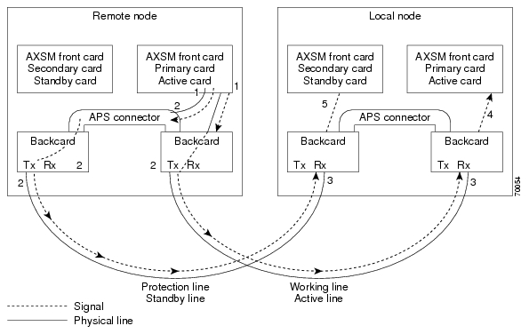
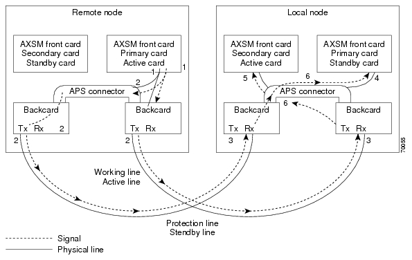
Figure 1 shows an example of how this process operates in a standard APS configuration, where the primary card monitors the working line and the secondary card monitors the protection line.
Figure 2 shows an example of how the APS communication process operates in a crossed APS configuration, where the secondary card monitors the working line that is attached to the primary card, and the primary card monitors the protection line that is connected to the secondary card.
Figure 1
Standard APS Configuration
Figure 2
Crossed APS Configuration
Line failures are always detected at the receive end of the line. This is where a switchover occurs when a failure is detected. Two different types of switchovers can occur, depending on whether the APS was configured as unidirectional or bidirectional in the cnfapsln command:
•When a failure occurs on a line configured for unidirectional switching, the switch changes lines at the receive end only. A switchover is not necessary at the transmit end because the transmitting back cards send signals on both lines in the 1 +1 APS configuration.
•When a failure occurs on a line configured for bidirectional switching, a switchover occurs at both ends of the line.
If the status of the standby line is good, a switchover from the failed active line to the standby is automatic.
Enter the cnfapsln command to enable an automatic switchover back to the working line after it recovers from a failure, as shown in the following example:
M8xx0_LA.1.AXSM.a > cnfapsln -w 1.1.1 -rv 2Table 16 describes the configurable parameters for the cnfapsln command.
If you want to manually switch from one line to another, enter the switchapsln <bay> <line> <switchOption> command, as shown in the following example:
M8xx0_LA.1.AXSM.a > switchapsln 1 1 6Manual line switch from protection to working succeeded on line 1.1.1Table 17 describes the configurable parameters for the cnfapsln command.
Enter the dspapslns command to verify that the active line switched over from the protection line to the working line, as shown in the following example:
M8xx0_LA.1.AXSM.a > dspapslnsWorking Prot. Conf Oper Active WLine PLine WTR Revt Conf Oper LastUserIndex Index Arch Arch Line State State (min) Dir Dir SwitchReq------- ----- ---- ----- ------ ----- ----- ----- ---- ---- ---- ----------1.1.1 2.1.1 1+1 1+1 working OK OK 5 Yes bi bi ManualP->WTroubleshooting APS Lines
Port light behavior changed in Release 3.0.00 as follows:
Port lights on AXSM /B front cards indicate the receive status of APS lines. The active front card always displays the status of the active line. The standby card always displays the status of the inactive line. If only one APS line fails, the line failure LED is always displayed on the standby front card.
Port lights on AXSMB front cards indicate the receive status of the Physical Line connected to it. For example, when APS is configured for working line as 5.1.3 and protection line as 6.1.3, regardless of which card is active, port LED on card 5 will show the receive status of 5.1.3 and card 6 will show the receive status of 6.1.3.
Note The remainder of this section is the same as for Release 2.1.80 unless otherwise noted as updated for Release 3.0.00.
Caution When the active front card and the active line are in different slots and the inactive line has failed, it is easy to incorrectly identify the failed line as the line in the standby slot. To avoid disrupting traffic through the active line, verify which physical line is at fault before disconnecting the suspect line.
If the active line fails and the standby line is not available, the switch reports a critical alarm.
If the active line fails and the standby line takes over, the former standby line becomes the new active line, and the switch reports a major alarm.
If an AXSM/A front card fails, APS communication between the redundant front cards fails. This can result in one of the following situations:
•If both APS lines were working before the failure, an APS line failure causes a switchover to the protection line
•If either APS line failed prior to a front card failure, a failure on the active line does not cause a switchover to the other line. Because the standby front card failed, it cannot monitor the standby line and report when the line has recovered. This means that the active card cannot use the standby line until the standby front card is replaced and the line problem corrected.
Use the following procedure to troubleshoot APS lines.
Step 1 Enter the dsplns command to determine if the line in alarm is an APS line. The dsplns command shows which lines are enabled for APS:
M8xx0_.1.AXSM.a > dsplnsMedium MediumSonet Line Line Line Frame Line Line Alarm APSLine State Type Lpbk Scramble Coding Type State Enabled----- ----- ------------ ------ -------- ------ ------- ----- --------1.1 Up sonetSts12c NoLoop Enable Other ShortSMF Clear Enable1.2 Up sonetSts12c NoLoop Enable Other ShortSMF Clear Disable2.1 Up sonetSts12c NoLoop Enable Other ShortSMF Clear Disable2.2 Up sonetSts12c NoLoop Enable Other ShortSMF Clear DisableIf the line in alarm is an APS line, and has always functioned properly as an APS line, proceed to Step 2.
If the line in alarm has never functioned properly as an APS line, verify that the following are true:
•redundant front and back cards are in the appropriate bays and are installed at both ends of the line.
•cable is properly connected to both ends of the line.
•enter the dspapsbkplane command to verify that the APS connector is installed properly at both ends of the line.
Step 2 Enter the dspapslns command at both ends of the communication line to determine whether one or both lines in an APS pair are bad. Use Table 18 to help you determine which APS line is not functioning properly.
Note Table 18 is updated for Release 3.0.00.
Table 18 Troubleshooting APS Line Problems Using the dspaps Command
Active Line Working Line Protection Line Working Line LED Protection LineLED DescriptionWorking
OK
OK
Green
Green
Active card is receiving signal on working and protection lines. This does not guarantee that transmit lines are functioning properly. You must view the status on remote switch.
Protection
SF
OK
Green for
AXSM/A, Red for AXSM/A, Green for AXSM/BRed
Active card is receiving signal on the protection line. No signal received on the working line.
Working
OK
SF
Green
Red
Active card is receiving signal on the working line. No signal received on the protection line.
Working
SF
SF
Red
Red
Active card is not receiving signal from either line. The working line was the last line to work.
Protection
SF
SF
Red
Red
Active card is not receiving signal from either line. The protection line was the last line to work.
Working
UNAVAIL
UNAVAIL
The card set is not complete. One or more cards have failed or been removed. See Table 19 to troubleshoot card errors.
If one or both lines appear to be bad, determine whether the working or protection line is in alarm. Troubleshoot and correct the standby line first. Replace the components along the signal path until the problem is resolved.
•If the dspapslns command at either end of the line indicates a front or back card problem, resolve that problem first. (See Table 19 to troubleshoot card problems).
•If the dspapslns command shows a signal failure on the standby line, replace that line.
•If the standby line is still down, replace the cards along the signal path.
Installation and Upgrade Procedures
For information on the following installation and upgrade procedures, please refer to the Cisco MGX 8850 (PXM1E/PXM45), Cisco MGX 8950, and Cisco MGX 8830 Software Configuration Guide, Release 4, part OL-3845-01.
Upgrade Information
The upgrade appendix in the Cisco MGX 8850 (PXM1E/PXM45), Cisco MGX 8950, and Cisco MGX 8830 Software Configuration Guide, Release 4 contains the following procedures:
•Graceful PXM1E Boot Upgrades from Release 3.0
•Graceful PXM1E Boot Upgrades from Release 3.0.20
•Non-Graceful PXM1E Boot Upgrades
•Graceful PXM1E Runtime Software Upgrades
•Non-Graceful PXM1E Runtime Software Upgrades
•Graceful PXM45, AXSM, and FRSM-12-T3E3 Runtime Software Upgrades
•Non-Graceful PXM45, AXSM, and FRSM-12-T3E3 Runtime Software Upgrades
•Graceful AXSM or FRSM-12-T3E3 Boot Upgrades
•Non-Graceful AXSM or FRSM-12-T3E3 Boot Upgrades
•Graceful Service Module Boot Upgrades
•Non-Graceful Service Module Boot Upgrades
•Graceful Service Module Runtime Software Upgrades
•Non-Graceful Service Module Runtime Software Upgrades
•Graceful RPM-PR Boot Software Upgrades
•Graceful RPM-PR Runtime Software Upgrades
•Non-Graceful RPM-PR Boot Software Upgrades
•Non-Graceful RPM-PR Runtime Software Upgrades
•Installing SCT Files
Maintenance Information
The upgrade appendix in the Cisco MGX 8850 (PXM1E/PXM45), Cisco MGX 8950, and Cisco MGX 8830 Software Configuration Guide, Release 4 contains the following procedures:
•Replacing PXM1E-4-155 cards and with PXM1E-8-155 Cards
•Replacing PXM45/A or PXM45/B Cards with PXM45/C Cards
Upgrade Limitations
When connections are built on an AXSM_B card with software version 2.1(80) and the card is replaced with a regular AXSM, the connections remain OK. When this node is upgraded to Release 3.0.10, the card will go into a mismatch state indicating that the reserved card is an AXSM_B. See anomaly CSCdz72564 for details.
Frame Discard
Note An important caveat exists for virtual path connections (VPCs) that were added with frame discard enabled before version 3.0.23 or 4.0.10. The switch lets you enable frame discard on a VPC, even though hardware does not support it. If a VPC with frame discard enabled already existed on the node when you upgrade to release 3.0.23, 4.0.10, or later, you cannot subsequently modify the VPC unless you delete it, then re-add it with frame discard disabled. To avoid the need to delete a VPC, disable frame discard on any such VPCs before you upgrade to MGX releases 3.0.23, 4.0.10, or later.
The order of software releases was as follows:
•MGX 4.0.00 April 2003
•MGX 3.0.23 May 2003
•MGX 4.0.10 August 2003
•MGX 4.0.11 October 2003
•MGX 4.0.12 October 2003
•MGX 3.0.25 December 2003
Documentation
Please note the following important information about release notes and technical manuals.
Changes to this Document
Table 20 describes changes made to these release notes that caused the release notes to go from OL-3245-01 Rev. C0, June 20, 2003 to OL-3245-01 Rev. D0 on January 21, 2004.
Notes
•The technical documentation that supports this release may include descriptions of features not implemented as of this printing.
•Starting in May 2003, the documents listed in the "Related Documentation" section will be available online only. Release Notes became available online only for our June 2002 release. Refer to the "How to Find Multiservice Switch Customer Documents Online" section for notes on how to locate documents online.
•A new manual, MGX and SES Error Messages, Release 4, became available as this release note went into production. This manual is for network operators. The manual describes error messages on the MGX 8850 (PXM45), MGX 8850 (PXM1E), MGX 8950, MGX 8830, and Service Expansion Shelf (SES), and suggests possible corrective actions. This manual is part number OL-4290-01.
Related Documentation
This "Related Documentation" section describes the technical manuals and release notes listed in the "Guide to Cisco Multiservice Switch Documentation." That guide, part DOC-7815358=, shipped with your product.
The following Cisco publications contain information related to the operation of this product and associated equipment in a Cisco WAN switching network.
Cisco WAN Manager Release 12
Table 21 lists the product documentation for the Cisco WAN Manager (CWM) network management system for Release 12.
Cisco MGX 8850 (PXM45) Multiservice Switch Release 4
Table 22 lists the product documentation for the installation and operation of the Cisco MGX 8850 (PXM45) Multiservice Switch Release 4.
Cisco MGX 8850 (PXM1E) Multiservice Switch Release 4
Table 23 lists the product documentation for the installation and operation of the Cisco MGX 8850 (PXM1E) Multiservice Switch Release 4.
Cisco MGX 8950 Multiservice Service Release 4
Table 24 lists the product documentation for the installation and operation of the Cisco MGX 8950 Multiservice Switch Release 4.
SES PNNI Release 4
Table 25 lists product documentation for understanding, installing, and operating the Service Expansion Shelf (SES) Private Network-to-Network Interface (PNNI) Controller.
Cisco MGX 8830 Multiservice Switch Release 4
Table 26 lists the product documentation for the installation and operation of the Cisco MGX 8830 Multiservice Switch Release 4.
Cisco WAN Switching Software Release 9.4
Table 27 lists the product documentation for the installation and operation of the Cisco WAN Switching Software Release 9.4.
MGX 8850 (PXM1) Edge Concentrator Release 1.2.20
Note The Release 1.x books have not been updated recently. Please check the Release Notes for the latest information.
Table 28 lists the product documentation for the installation and operation of the Cisco MGX 8850 Edge Concentrator.
MGX 8250 Edge Concentrator Release 1.2.20
Table 29 lists the product documentation for the installation and operation of the Cisco MGX 8250 Edge Concentrator.
MGX 8230 Edge Concentrator Release 1.2.20
Table 30 lists the product documentation for the installation and operation of the Cisco MGX 8230 Edge Concentrator.
How to Find Multiservice Switch Customer Documents Online
There are several ways you can find Multiservice Switch customer documents online.
If the Part Number is Known
Use the following procedure if you know or can find the document's part number.
Step 1 Obtain the document's part number from the "Guide to Multiservice Switch Documentation" that shipped with your product, or from the "Related Documentation" section in this Preface.
Step 2 In your browser's URL field, type www.cisco.com.
Step 3 In the top right search field, enter the document part number (for example, OL-3842-01) and click on GO.
If the Part Number is Not Known
Use the following procedures if you do not know or cannot find the document's part number.
Finding Cisco WAN Manager Documents
To find Cisco WAN Manager customer documents online:
Step 1 In your browser's URL field, type http://www.cisco.com/univercd/cc/td/doc/product/rtrmgmt/cwm.
Step 2 Look for the CWM release number.
Finding Multiservice Switch Documents
To find Multiservice Switch customer documents online:
Step 1 In your browser's URL field, type http://www.cisco.com/univercd/cc/td/doc/product/wanbu/index.htm.
Step 2 Look for the switch name, then release number (for example, MGX 8850 (PXM1E), then Release 4).
Ordering Documentation
Note Starting in April 2003, the documents listed in the "Related Documentation" section will be available online only. To access these documents online, refer to the "How to Find Multiservice Switch Customer Documents Online" section.
Other Cisco documentation is available in the following ways:
•Registered Cisco Direct Customers can order printed Cisco product documentation from the Networking Products MarketPlace:
http://www.cisco.com/cgi-bin/order/order_root.pl
Some printed documentation is offered through the "Printed Information Ordering" site, which can be accessed through:
http://www.cisco.com/univercd/cc/td/doc/es_inpck/pdi.htm
•Registered Cisco.com users can order the Documentation CD-ROM through the online Subscription Store:
http://www.cisco.com/go/subscription
•Non-registered Cisco.com users can order documentation through a local account representative by calling Cisco corporate headquarters (California, USA) at 408 526-7208 or, in North America, by calling 800 553-NETS(6387).
Documentation on the World Wide Web
You can access the most current Cisco documentation on the World Wide Web at the following sites:
•http://www.cisco.com (for example, http://www.cisco.com/univercd/cc/td/doc/product/wanbu/index.htm)
•http://www-china.cisco.com
•http://www-europe.cisco.com
Documentation CD-ROM
Cisco documentation and additional literature are available in a CD-ROM package, which ships with your product. The Documentation CD-ROM is updated monthly and may be more current than printed documentation. The CD-ROM package is available as a single unit or as an annual subscription as mentioned above.
Documentation Feedback
If you are reading Cisco product documentation on the World Wide Web, you can submit technical comments electronically. Click Feedback in the toolbar and select Documentation. After you complete the form, click Submit to send it to Cisco.
You can e-mail your comments to bug-doc@cisco.com.
To submit your comments by mail, use the response card behind the front cover of your document, or write to the following address:
Attn: Document Resource Connection
Cisco Systems, Inc.
170 West Tasman Drive
San Jose, CA 95134-9883We appreciate your comments.
Technical Assistance
Cisco provides Cisco.com as a starting point for all technical assistance. Customers and partners can obtain documentation, troubleshooting tips, and sample configurations from online tools. For Cisco.com registered users, additional troubleshooting tools are available from the TAC website.
Cisco.com
Cisco.com is the foundation of a suite of interactive, networked services that provides immediate, open access to Cisco information and resources at anytime, from anywhere in the world. This highly integrated Internet application is a powerful, easy-to-use tool for doing business with Cisco.
Cisco.com provides a broad range of features and services to help customers and partners streamline business processes and improve productivity. Through Cisco.com, you can find information about Cisco and our networking solutions, services, and programs. In addition, you can resolve technical issues with online technical support, download and test software packages, and order Cisco learning materials and merchandise. Valuable online skill assessment, training, and certification programs are also available.
Customers and partners can self-register on Cisco.com to obtain additional personalized information and services. Registered users can order products, check on the status of an order, access technical support, and view benefits specific to their relationships with Cisco.
To access Cisco.com, go to http://www.cisco.com
Technical Assistance Center
The Cisco TAC website is available to all customers who need technical assistance with a Cisco product or technology that is under warranty or covered by a maintenance contract.
Contacting TAC by Using the Cisco TAC Website
If you have a priority level 3 (P3) or priority level 4 (P4) problem, contact TAC by going to the TAC website:
http://www.cisco.com/tac
P3 and P4 level problems are defined as follows:
•P3—Your network performance is degraded. Network functionality is noticeably impaired, but most business operations continue.
•P4—You need information or assistance on Cisco product capabilities, product installation, or basic product configuration.
In each of the above cases, use the Cisco TAC website to quickly find answers to your questions.
Note To register for Cisco.com, go to http://www.cisco.com/register/
If you cannot resolve your technical issue by using the TAC online resources, Cisco.com registered users can open a case online by using the TAC Case Open tool at http://www.cisco.com/tac/caseopen
Contacting TAC by Telephone
If you have a priority level 1(P1) or priority level 2 (P2) problem, contact TAC by telephone and immediately open a case. To obtain a directory of toll-free numbers for your country, go to the following website:
http://www.cisco.com/warp/public/687/Directory/DirTAC.shtml
P1 and P2 level problems are defined as follows:
•P1—Your production network is down, causing a critical impact to business operations if service is not restored quickly. No workaround is available.
•P2—Your production network is severely degraded, affecting significant aspects of your business operations. No workaround is available.
Caveats
This section provides information about known anomalies.
MGX 8850, MGX 8830, and MGX 8950 Anomalies
Severity level 1, 2, and 3 anomalies are organized as follows:
•Known Anomalies in Release 4.0.00
•Anomalies Resolved in Release 4.0.00
Known Anomalies in Release 4.0.00
Table 31 lists the anomalies and known workarounds for Release 4.
Known Route Processor Module or MPLS Anomalies
For information about anomalies with the RPM-PR or RPM/B card, refer to "Release Notes for Cisco MGX Route Processor Module (RPM/B and RPM-PR) for MGX Release 1.2.10 and MGX Release 3."
For information about anomalies with the RPM-XF card, refer to "Release Notes for Cisco MGX Route Processor Module (RPM-XF) for MGX 8850 Release 3.0.00 (PXM45)."
MGX-RPM-XF-512 Anomalies
The new MGX-RPM-XF-512 card supports MGX 8850 (PXM45), Release 3.0.00.
For information about anomalies with the MGX-RPM-XF-512 card, refer to "Release Notes for Cisco MGX Route Processor Module (RPM-XF) for Release 3.0.00 of MGX 8850 (PXM45)".
Acronyms
Table 32 lists acronyms that have been referenced in these release notes.
This document is to be used in conjunction with the documents listed in the "Related Documentation" section.
CCIP, CCSP, the Cisco Arrow logo, the Cisco Powered Network mark, Cisco Unity, Follow Me Browsing, FormShare, and StackWise are trademarks of Cisco Systems, Inc.; Changing the Way We Work, Live, Play, and Learn, and iQuick Study are service marks of Cisco Systems, Inc.; and Aironet, ASIST, BPX, Catalyst, CCDA, CCDP, CCIE, CCNA, CCNP, Cisco, the Cisco Certified Internetwork Expert logo, Cisco IOS, the Cisco IOS logo, Cisco Press, Cisco Systems, Cisco Systems Capital, the Cisco Systems logo, Empowering the Internet Generation, Enterprise/Solver, EtherChannel, EtherSwitch, Fast Step, GigaStack, Internet Quotient, IOS, IP/TV, iQ Expertise, the iQ logo, iQ Net Readiness Scorecard, LightStream, MGX, MICA, the Networkers logo, Networking Academy, Network Registrar, Packet, PIX, Post-Routing, Pre-Routing, RateMUX, Registrar, ScriptShare, SlideCast, SMARTnet, StrataView Plus, Stratm, SwitchProbe, TeleRouter, The Fastest Way to Increase Your Internet Quotient, TransPath, and VCO are registered trademarks of Cisco Systems, Inc. and/or its affiliates in the United States and certain other countries.
All other trademarks mentioned in this document or Website are the property of their respective owners. The use of the word partner does not imply a partnership relationship between Cisco and any other company. (0401R)
Copyright © 2003, 2004 Cisco Systems, Inc.
All rights reserved.