Feedback
Contents
- Configuring QoS
- Finding Feature Information
- Prerequisites for QoS
- QoS Components
- QoS Terminology
- Information About QoS
- QoS Overview
- Modular QoS Command-Line Interface
- Wireless QoS Overview
- QoS and IPv6 for Wireless
- Wired and Wireless Access Supported Features
- Supported QoS Features on Wireless Targets
- Port Policies
- Port Policy Format
- Radio Policies
- SSID Policies
- Client Policies
- Hierarchical QoS
- Hierarchical Wireless QoS
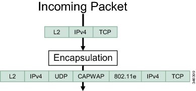
- Wireless Packet Format
- Hierarchical AFD
- QoS Implementation
- Layer 2 Frame Prioritization Bits
- Layer 3 Packet Prioritization Bits
- End-to-End QoS Solution Using Classification
- Packet Classification
- Classification Based on Information That is Propagated with the Packet
- Classification Based on Layer 3 or Layer 4 Header
- Classification Based on Layer 2 Header
- Classification Based on Information that is Device Specific (QoS Groups)
- Hierarchical Classification
- QoS Wired Model
- Ingress Port Activity
- Egress Port Activity
- Classification
- Access Control Lists
- Class Maps
- Policy Maps
- Policy Map on Physical Port
- Policy Map on VLANs
- Wireless QoS Rate Limiting
- Wireless QoS Multicast
- Policing
- Token-Bucket Algorithm
- Marking
- Packet Header Marking
- Switch Specific Information Marking
- Table Map Marking
- Traffic Conditioning
- Policing
- Single-Rate Two-Color Policing
- Dual-Rate Three-Color Policing
- Shaping
- Class-Based Traffic Shaping
- Average Rate Shaping
- Hierarchical Shaping
- Queueing and Scheduling
- Bandwidth
- Bandwidth Percent
- Bandwidth Remaining Ratio
- Weighted Tail Drop
- Weighted Tail Drop Default Values
- Priority Queues
- Queue Buffer
- Queue Buffer Allocation
- Dynamic Threshold and Scaling
- Queuing in Wireless
- Trust Behavior
- Trust Behavior for Wired and Wireless Ports
- Port Security on a Trusted Boundary for Cisco IP Phones
- Wireless QoS Mobility
- Inter-Switch Roaming
- Intra-Switch Roaming
- Precious Metal Policies for Wireless QoS
- Standard QoS Default Settings
- Default Wired QoS Configuration
- DSCP Maps
- Default CoS-to-DSCP Map
- Default IP-Precedence-to-DSCP Map
- Default DSCP-to-CoS Map
- Default Wireless QoS Configuration
- Restrictions for QoS on Wired Targets
- Restrictions for QoS on Wireless Targets
- How to Configure QoS
- Configuring Class, Policy, and Table Maps
- Creating a Traffic Class (CLI)
- Creating a Traffic Policy (CLI)
- Configuring Client Policies (GUI)
- Configuring Class-Based Packet Marking (CLI)
- Configuring Class Maps for Voice and Video (CLI)
- Attaching a Traffic Policy to an Interface (CLI)
- Configuring SSID Policies (GUI)
- Applying an SSID or Client Policy on a WLAN (CLI)
- Classifying, Policing, and Marking Traffic on Physical Ports by Using Policy Maps (CLI)
- Classifying, Policing, and Marking Traffic on SVIs by Using Policy Maps (CLI)
- Configuring Table Maps (CLI)
- Configuring Trust
- Configuring Trust Behavior for Wireless Traffic (CLI)
- Configuring QoS Features and Functionality
- Configuring Call Admission Control (CLI)
- Configuring Bandwidth (CLI)
- Configuring Police (CLI)
- Configuring Priority (CLI)
- Configuring Queues and Shaping
- Configuring Egress Queue Characteristics
- Configuring Queue Buffers (CLI)
- Configuring Queue Limits (CLI)
- Configuring Shaping (CLI)
- Configuring Precious Metal Policies (CLI)
- Configuring QoS Policies for Multicast Traffic (CLI)
- Applying a QoS Policy on a WLAN (GUI)
- Monitoring QoS
- Configuration Examples for QoS
- Examples: Classification by Access Control Lists
- Examples: Class of Service Layer 2 Classification
- Examples: Class of Service DSCP Classification
- Examples: VLAN ID Layer 2 Classification
- Examples: Classification by DSCP or Precedence Values
- Examples: Hierarchical Classification
- Examples: Hierarchical Policy Configuration
- Examples: Classification for Voice and Video
- Examples: Wireless QoS Policy Classified by Voice, Video, and Multicast Traffic
- Examples: Configuring Downstream SSID Policy
- Examples: Client Policies
- Examples: Average Rate Shaping Configuration
- Examples: Queue-limit Configuration
- Examples: Queue Buffers Configuration
- Examples: Policing Action Configuration
- Examples: Policer VLAN Configuration
- Examples: Policing Units
- Examples: Single-Rate Two-Color Policing Configuration
- Examples: Dual-Rate Three-Color Policing Configuration
- Examples: Table Map Marking Configuration
- Example: Table Map Configuration to Retain CoS Markings
- Where to Go Next
- Additional References for QoS
- Feature History and Information for QoS
Configuring QoS
- Finding Feature Information
- Prerequisites for QoS
- QoS Components
- QoS Terminology
- Information About QoS
- Restrictions for QoS on Wired Targets
- Restrictions for QoS on Wireless Targets
- How to Configure QoS
- Monitoring QoS
- Configuration Examples for QoS
- Where to Go Next
- Additional References for QoS
- Feature History and Information for QoS
Finding Feature Information
Your software release may not support all the features documented in this module. For the latest feature information and caveats, see the release notes for your platform and software release.
Use Cisco Feature Navigator to find information about platform support and Cisco software image support. To access Cisco Feature Navigator, go to http://www.cisco.com/go/cfn. An account on Cisco.com is not required.
Prerequisites for QoS
Before configuring standard QoS, you must have a thorough understanding of these items:
- Standard QoS concepts.
- Wireless concepts and network topologies.
- Classic Cisco IOS QoS.
- Modular QoS CLI (MQC).
- Understanding of QoS implementation.
- The types of applications used and the traffic patterns on your network.
- Traffic characteristics and needs of your network. For example, is the traffic on your network bursty? Do you need to reserve bandwidth for voice and video streams?
- Bandwidth requirements and speed of the network.
- Location of congestion points in the network.
Related Concepts
Related References
QoS Components
QoS consists of the following key components:
- Classification— Classification is the process of distinguishing one type of traffic from another based upon ACLs, Differentiated Services Code Point (DSCP), Class of Service (CoS), and other factors.
- Marking and mutation— Marking is used on traffic to convey specific information to a downstream device in the network, or to carry information from one interface in a switch to another. When traffic is marked, QoS operations on that traffic can be applied. This can be accomplished directly using the set command or through a table map, which takes input values and translates them directly to values on output.
- Shaping and policing— Shaping is the process of imposing a maximum rate of traffic, while regulating the traffic rate in such a way that downstream devices are not subjected to congestion. Shaping in the most common form is used to limit the traffic sent from a physical or logical interface. Policing is used to impose a maximum rate on a traffic class. If the rate is exceeded, then a specific action is taken as soon as the event occurs.
- Queuing — Queueing is used to prevent traffic congestion. Traffic is sent to specific queues for servicing and scheduling based upon bandwidth allocation. Traffic is then scheduled or sent out through the port.
- Bandwidth—Bandwidth allocation determines the available capacity for traffic that is subject to QoS policies.
- Trust— Trust enables traffic to pass through the switch, and the DSCP, precedence, or CoS values coming in from the end points are retained in the absence of any explicit policy configuration.
QoS Terminology
The following terms are used interchangeably in this QoS configuration guide:
- Upstream (direction towards the switch) is the same as ingress.
- Downstream (direction from the switch) is the same as egress.
NoteUpstream is wireless to wired. Downstream is wired to wireless. Wireless to wireless has no specific term.
Information About QoS
QoS Overview
By configuring the quality of service (QoS), you can provide preferential treatment to specific types of traffic at the expense of other traffic types. Without QoS, the switch offers best-effort service to each packet, regardless of the packet contents or size. The switch sends the packets without any assurance of reliability, delay bounds, or throughput.
The following are specific features provided by QoS:
- Modular QoS Command-Line Interface
- Wireless QoS Overview
- QoS and IPv6 for Wireless
- Wired and Wireless Access Supported Features
- Supported QoS Features on Wireless Targets
- Port Policies
- Radio Policies
- SSID Policies
- Client Policies
- Hierarchical QoS
- Hierarchical Wireless QoS
Related Concepts
Related References
Modular QoS Command-Line Interface
With the switch, QoS features are enabled through the Modular QoS command-line interface (MQC). The MQC is a command-line interface (CLI) structure that allows you to create traffic policies and attach these policies to interfaces. A traffic policy contains a traffic class and one or more QoS features. A traffic class is used to classify traffic, while the QoS features in the traffic policy determine how to treat the classified traffic. One of the main goals of MQC is to provide a platform-independent interface for configuring QoS across Cisco platforms.
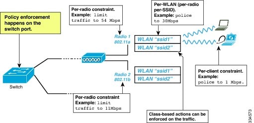
Wireless QoS Overview
Wireless QoS can be configured on the following wireless targets:
- Wireless ports, including all physical ports to which an access point can be associated.
- Radio
- SSID (applicable on a per-radio, per-AP, and per-SSID)
- Client
The following table displays how policies are supported for the wireless targets.
Table 1 Wireless Targets Policies Support Wireless Target
Policies on Wireless Targets Supported
Policies Supported Downstream Direction
Policies Supported Upstream Direction
Wireless port
Yes
Yes - user configurable
No
Radio
Yes
Yes - but not configurable by user
No
SSID
Yes
Yes - user configurable
Yes - user configurable
Client
Yes
Yes - user configurable
Yes - user configurable
NoteAdditional polices that are user configured include multi-destination policers and VLANs.
Wireless QoS supports the following additional features:
QoS and IPv6 for Wireless
From this release onwards, the switch supports QoS for both IPv4 and IPv6 traffic, and client policies can now have IPv4 and IPv6 filters.
Wired and Wireless Access Supported Features
Related Concepts
Supported QoS Features on Wireless Targets
This table describes the various features available on wireless targets.
Table 3 QoS Features Available on Wireless TargetsTarget Features Traffic Direction Where Policies Are Applicable Comments Port Non-Real Time (NRT), Real Time (RT) Downstream Radio Non-Real Time Downstream Radio policies are not user configurable. SSID Non-Real Time, Real Time Upstream and downstream Queuing actions such as shaping and BRR are allowed only in the downstream direction. Client Non-Real Time, Real time Upstream and downstream
Port Policies
The switch supports port-based policies. The port policies includes port shaper and a child policy (port_child_policy).
NotePort child policies only apply to wireless ports and not to wired ports on the switch. A wireless port is defined as a port to which APs join. A default port child policy is applied on the switch to the wireless ports at start up.The port shaper rate is limited to 1G
Port shaper specifies the traffic policy applicable between the device and the AP. This is the sum of the radio rates supported on the access point.
The child policy determines the mapping between packets and queues defined by the port-child policy. The child policy can be configured to include voice, video, class-default, and non-client-nrt classes where voice and video are based on DSCP value (which is the outer CAPWAP header DSCP value). The definition of class-default is known to the system as any value other than voice and video DSCP.
The DSCP value is assigned when the packet reaches the port. Before the packet arrives at the port, the SSID policies are applied on the packet. Port child policy also includes multicast percentage for a given port traffic. By default, the port child policy allocates up to 10 percent of the available rate.
Related Tasks
Related References
Port Policy Format
This section describes the behavior of the port policies on a switch. The ports on the switch do not distinguish between wired or wireless physical ports. Depending on the kind of device associated to the switch, the policies are applied. For example, when an access point is connected to a switch port, the switch detects it as a wireless device and applies the default hierarchical policy which is in the format of a parent-child policy. This policy is an hierarchical policy. The parent policy cannot be modified but the child policy (port-child policy) can be modified to suit the QoS configuration. The switch is pre configured with a default class map and a policy map.
Default class map:Class Map match-any non-client-nrt-class Match non-client-nrtThe above port policy processes all network traffic to the Q3 queue. You can view the class map by executing the show class-map command.
Default policy map:Policy Map port_child_policy Class non-client-nrt-class bandwidth remaining ratio 10
Note
The class map and policy map listed are system-defined policies and cannot be changed.
The following is the system-defined policy map available on the ports on which wireless devices are associated. The format consists of a parent policy and a service child policy (port_child_policy). To customize the policies to suite your network needs, you must configure the port child policy.Policy-map policy_map_name Class class-default Shape average average_rate Service-policy port_child_policy
Note
The parent policy is system generated and cannot be changed. You must configure the port_child_policy policy to suit the QoS requirements on your network.
Depending on the type of traffic in your network, you can configure the port child policy. For example, in a typical wireless network deployment, you can assign specific priorities to voice and video traffic. Here is an example:
Policy-map port_child_policy
     Class  voice-policy-name (match dscp ef)
          Priority level 1
         Police (multicast-policer-name-voice) Multicast Policer
    Class video-policy-name (match dscp af41)
        Priority level 2
        Police (multicast-policer-name-video) Multicast Policer
Class non-client-nrt-class traffic(match non-client-nrt)
        Bandwidth remaining ratio (brr-value-nrt-q2)
    Class class-default  (NRT Data)
        Bandwidth remaining ratio (brr-value-q3)
In the above port child policy:In the above sample configuration, all voice and video traffic is directed to the Q0 and Q1 queues, respectively. These queues maintain a strict priority. The packets in Q0 and Q1 are processed in that order. The bandwidth remaining ratios brr-value-nrt-q2 and brr-value-q3 are directed to the Q2 and Q3 respectively specified by the class maps and class-default and non-client-nrt. The processing of packets on Q2 and Q3 are based on a weighted round-robin approach. For example, if the brr-value-nrtq2 has a value of 90 and brr-value-nrtq3 is 10, the packets in queue 2 and queue 3 are processed in the ratio of 9:1.
- voice-policy-name— Refers to the name of the class that specifies rules for the traffic for voice packets. Here the DSCP value is mapped to a value of 46 (represented by the keyword ef). The voice traffic is assigned the highest priority of 1.
- video-policy-name— Refers to the name of the class that specifies rules for the traffic for video packets. The DSCP value is mapped to a value of 34 (represented by the keyword af41).
- multicast-policer-name-voice— If you need to configure multicast voice traffic, you can configure policing for the voice class map.
- multicast-policer-name-video— If you need to configure multicast video traffic, you can configure policing for the video class map.
Related Concepts
Related Tasks
Radio Policies
The radio policies are system defined and are not user configurable. Radio wireless targets are only applicable in the downstream direction.
Radio policies are applicable on a per-radio, per-access point basis. The rate limit on the radios is the practical limit of the AP radio rate. This value is equivalent to the sum of the radios supported by the access point.
Related Concepts
Related References
SSID Policies
You can create QoS policies on SSID BSSID (Basic Service Set Identification) in both the upstream and downstream directions. By default, there is no SSID policy. You can configure an SSID policy based on the SSID name. The policy is applicable on a per BSSID.
The types of policies you can create on SSID include marking by using table maps (table-maps), shape rate, and RT1 (Real Time 1) and RT2 (Real Time 2) policiers. If traffic is upstream, you usually configure a marking policy on the SSID. If traffic is downstream, you can configure marking and queuing.
There should be a one-to-one mapping between the policies configured on a port and an SSID. For example, if you configure class voice and class video on the port, you can have a similar policy on the SSID.
SSID priorities can be specified by configuring bandwidth remaining ratio. Queuing SSID policies are applied in the downstream direction.
Related Concepts
Related Tasks
Client Policies
Client policies are applicable in the upstream and downstream direction. The wireless control module of the switch applies the default client policies when admission control is enabled for WMM clients. When admission control is disabled, there is no default client policy. You can configure policing and marking policies on clients.
NoteA client policy can have both IPv4 and IPv6 filters.
You can configure client policies in the following ways:
- Using AAA—You can use a combination of AAA and TCLAS, and AAA and SIP snooping when configuring with AAA.
- Using the Cisco IOS MQC CLI—You can use a combination of CLI and TCLAS and CLI and SIP snooping.
- Using the default configuration
Note
When applying client policies on a WLAN, you must disable the WLAN before modifying the client policy. SSID policies can be modified even if the WLAN is enabled.
NoteIf you configured AAA by configuring the unified wireless controller procedure, and using the MQC QoS commands, the policy configuration performed through the MQC QoS commands takes precedence.
For client policies, the following filters are supported:
Related Concepts
Related Tasks
Related References
Hierarchical QoS
The switch supports hierarchical QoS (HQoS). HQoS allows you to perform:
- Hierarchical classification— Traffic classification is based upon other classes.
- Hierarchical policing—The process of having the policing configuration at multiple levels in a hierarchical policy.
- Hierarchical shaping—Shaping can also be configured at multiple levels in the hierarchy.
NoteHierarchical shaping is only supported for the port shaper, where for the parent you only have a configuration for the class default, and the only action for the class default is shaping.
Related References
Hierarchical Wireless QoS
The switch supports hierarchical QoS for wireless targets. Hierarchical QoS policies are applicable on port, radio, SSID, and client. QoS policies configured on the device (including marking, shaping, policing) can be applied across the targets. If the network contains non-realtime traffic, the non-realtime traffic is subject to approximate fair drop. Hierarchy refers to the process of application of the various QoS policies on the packets arriving to the device.
Hierarchical AFD
Approximate Fair Dropping (AFD) is a feature provided by the QoS infrastructure in Cisco IOS. For wireless targets, AFD can be configured on SSID (via shaping) and clients (via policing). AFD shaping rate is only applicable for downstream direction. Unicast real-time traffic is not subjected to AFD drops.
QoS Implementation
Typically, networks operate on a best-effort delivery basis, which means that all traffic has equal priority and an equal chance of being delivered in a timely manner. When congestion occurs, all traffic has an equal chance of being dropped.
When you configure the QoS feature, you can select specific network traffic, prioritize it according to its relative importance, and use congestion-management and congestion-avoidance techniques to provide preferential treatment. Implementing QoS in your network makes network performance more predictable and bandwidth utilization more effective.
The QoS implementation is based on the Differentiated Services (Diff-Serv) architecture, a standard from the Internet Engineering Task Force (IETF). This architecture specifies that each packet is classified upon entry into the network.
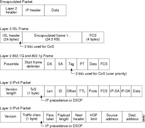
The classification is carried in the IP packet header, using 6 bits from the deprecated IP type of service (ToS) field to carry the classification (class) information. Classification can also be carried in the Layer 2 frame.
- Layer 2 Frame Prioritization Bits
- Layer 3 Packet Prioritization Bits
- End-to-End QoS Solution Using Classification
- Packet Classification
Related Concepts
Related References
Layer 2 Frame Prioritization Bits
Layer 2 Inter-Switch Link (ISL) frame headers have a 1-byte User field that carries an IEEE 802.1p class of service (CoS) value in the three least-significant bits. On ports configured as Layer 2 ISL trunks, all traffic is in ISL frames.
Layer 2 802.1Q frame headers have a 2-byte Tag Control Information field that carries the CoS value in the three most-significant bits, which are called the User Priority bits. On ports configured as Layer 2 802.1Q trunks, all traffic is in 802.1Q frames except for traffic in the native VLAN.
Other frame types cannot carry Layer 2 CoS values.
Layer 2 CoS values range from 0 for low priority to 7 for high priority.
End-to-End QoS Solution Using Classification
All switches and routers that access the Internet rely on the class information to provide the same forwarding treatment to packets with the same class information and different treatment to packets with different class information. The class information in the packet can be assigned by end hosts or by switches or routers along the way, based on a configured policy, detailed examination of the packet, or both. Detailed examination of the packet is expected to occur closer to the edge of the network, so that the core switches and routers are not overloaded with this task.
Switches and routers along the path can use the class information to limit the amount of resources allocated per traffic class. The behavior of an individual device when handling traffic in the Diff-Serv architecture is called per-hop behavior. If all devices along a path provide a consistent per-hop behavior, you can construct an end-to-end QoS solution.
Implementing QoS in your network can be a simple task or complex task and depends on the QoS features offered by your internetworking devices, the traffic types and patterns in your network, and the granularity of control that you need over incoming and outgoing traffic.
Packet Classification
Packet classification is the process of identifying a packet as belonging to one of several classes in a defined policy, based on certain criteria. The Modular QoS CLI (MQC) is a policy-class based language. The policy class language is used to define the following:
- Class-map template with one or several match criteria
- Policy-map template with one or several classes associated to the policy map
The policy map template is then associated to one or several interfaces on the switch.
Packet classification is the process of identifying a packet as belonging to one of the classes defined in the policy map. The process of classification will exit when the packet being processed matches a specific filter in a class. This is referred to as first-match exit. If a packet matches multiple classes in a policy, irrespective of the order of classes in the policy map, it would still exit the classification process after matching the first class.
If a packet does not match any of the classes in the policy, it would be classified into the default class in the policy. Every policy map has a default class, which is a system-defined class to match packets that do not match any of the user-defined classes.
Packet classification can be categorized into the following types:
- Classification Based on Information That is Propagated with the Packet
- Classification Based on Information that is Device Specific (QoS Groups)
- Hierarchical Classification
Classification Based on Information That is Propagated with the Packet
Classification that is based on information that is part of the packet and propagated either end-to-end or between hops, typically includes the following:
Classification Based on Layer 3 or Layer 4 Header
This is the most common deployment scenario. Numerous fields in the Layer 3 and Layer 4 headers can be used for packet classification.
At the most granular level, this classification methodology can be used to match an entire flow. For this deployment type, an access control list (ACLs) can be used. ACLs can also be used to match based on various subsets of the flow (for example, source IP address only, or destination IP address only, or a combination of both).
Classification can also be done based on the precedence or DSCP values in the IP header. The IP precedence field is used to indicate the relative priority with which a particular packet needs to be handled. It is made up of three bits in the IP header's type of service (ToS) byte.
The following table shows the different IP precedence bit values and their names.
Note IP precedence is not supported for wireless QoS.
Table 4 IP Precedence Values and NamesIP Precedence Value
IP Precedence Bits
IP Precedence Names
0
000
Routine
1
001
Priority
2
010
Immediate
3
011
Flash
4
100
Flash Override
5
101
Critical
6
110
Internetwork control
7
111
Network control
NoteAll routing control traffic in the network uses IP precedence value 6 by default. IP precedence value 7 also is reserved for network control traffic. Therefore, the use of IP precedence values 6 and 7 is not recommended for user traffic.
The DSCP field is made up of 6 bits in the IP header and is being standardized by the Internet Engineering Task Force (IETF) Differentiated Services Working Group. The original ToS byte contained the DSCP bits has been renamed the DSCP byte. The DSCP field is part of the IP header, similar to IP precedence. The DSCP field is a super set of the IP precedence field. Therefore, the DSCP field is used and is set in ways similar to what was described with respect to IP precedence.
NoteThe DSCP field definition is backward-compatible with the IP precedence values.
Classification Based on Layer 2 Header
A variety of methods can be used to perform classification based on the Layer 2 header information. The most common methods include the following:
- MAC address-based classification (only for access groups)—Classification is based upon the source MAC address (for policies in the input direction) and destination MAC address (for policies in the output direction).
- Class-of-Service—Classification is based on the 3 bits in the Layer 2 header based on the IEEE 802.1p standard. This usually maps to the ToS byte in the IP header.
- VLAN ID—Classification is based on the VLAN ID of the packet.
NoteSome of these fields in the Layer 2 header can also be set using a policy.
Classification Based on Information that is Device Specific (QoS Groups)
The switch also provides classification mechanisms that are available where classification is not based on information in the packet header or payload.
At times you might be required to aggregate traffic coming from multiple input interfaces into a specific class in the output interface. For example, multiple customer edge routers might be going into the same access switch on different interfaces. The service provider might want to police all the aggregate voice traffic going into the core to a specific rate. However, the voice traffic coming in from the different customers could have a different ToS settings. QoS group-based classification is a feature that is useful in these scenarios.
Policies configured on the input interfaces set the QoS group to a specific value, which can then be used to classify packets in the policy enabled on output interface.
The QoS group is a field in the packet data structure internal to the switch. It is important to note that a QoS group is an internal label to the switch and is not part of the packet header.
QoS Wired Model
To implement QoS, the switch must perform the following tasks:
- Traffic classification—Distinguishes packets or flows from one another.
- Traffic marking and policing—Assigns a label to indicate the given quality of service as the packets move through the switch, and then make the packets comply with the configured resource usage limits.
- Queuing and scheduling—Provides different treatment in all situations where resource contention exists.
- Shaping—Ensures that traffic sent from the switch meets a specific traffic profile.
Ingress Port Activity
The following activities occur at the ingress port of the switch:
- Classification—Classifying a distinct path for a packet by associating it with a QoS label. For example, the switch maps the CoS or DSCP in the packet to a QoS label to distinguish one type of traffic from another. The QoS label that is generated identifies all future QoS actions to be performed on this packet.
- Policing—Policing determines whether a packet is in or out of profile by comparing the rate of the incoming traffic to the configured policer. The policer limits the bandwidth consumed by a flow of traffic. The result is passed to the marker.
- Marking—Marking evaluates the policer and configuration information for the action to be taken when a packet is out of profile and determines what to do with the packet (pass through a packet without modification, mark down the QoS label in the packet, or drop the packet).
NoteApplying polices on the wireless ingress port is not supported on the switch.
Egress Port Activity
The following activities occur at the egress port of the switch:
- Policing—Policing determines whether a packet is in or out of profile by comparing the rate of the incoming traffic to the configured policer. The policer limits the bandwidth consumed by a flow of traffic. The result is passed to the marker.
- Marking—Marking evaluates the policer and configuration information for the action to be taken when a packet is out of profile and determines what to do with the packet (pass through a packet without modification, mark down the QoS label in the packet, or drop the packet).
- Queueing—Queueing evaluates the QoS packet label and the corresponding DSCP or CoS value before selecting which of the egress queues to use. Because congestion can occur when multiple ingress ports simultaneously send data to an egress port, Weighted Tail Drop (WTD) differentiates traffic classes and subjects the packets to different thresholds based on the QoS label. If the threshold is exceeded, the packet is dropped.
Classification
Classification is the process of distinguishing one kind of traffic from another by examining the fields in the packet. Classification is enabled only if QoS is enabled on the switch. By default, QoS is enabled on the switch.
During classification, the switch performs a lookup and assigns a QoS label to the packet. The QoS label identifies all QoS actions to be performed on the packet and from which queue the packet is sent.
Access Control Lists
You can use IP standard, IP extended, or Layer 2 MAC ACLs to define a group of packets with the same characteristics (class). You can also classify IP traffic based on IPv6 ACLs.
In the QoS context, the permit and deny actions in the access control entries (ACEs) have different meanings from security ACLs:
- If a match with a permit action is encountered (first-match principle), the specified QoS-related action is taken.
- If a match with a deny action is encountered, the ACL being processed is skipped, and the next ACL is processed.
- If no match with a permit action is encountered and all the ACEs have been examined, no QoS processing occurs on the packet, and the switch offers best-effort service to the packet.
- If multiple ACLs are configured on a port, the lookup stops after the packet matches the first ACL with a permit action, and QoS processing begins.
NoteWhen creating an access list, note that by default the end of the access list contains an implicit deny statement for everything if it did not find a match before reaching the end.
After a traffic class has been defined with the ACL, you can attach a policy to it. A policy might contain multiple classes with actions specified for each one of them. A policy might include commands to classify the class as a particular aggregate (for example, assign a DSCP) or rate-limit the class. This policy is then attached to a particular port on which it becomes effective.
You implement IP ACLs to classify IP traffic by using the access-list global configuration command; you implement Layer 2 MAC ACLs to classify non-IP traffic by using the mac access-list extended global configuration command.
Class Maps
A class map is a mechanism that you use to name a specific traffic flow (or class) and isolate it from all other traffic. The class map defines the criteria used to match against a specific traffic flow to further classify it. The criteria can include matching the access group defined by the ACL or matching a specific list of DSCP or IP precedence values. If you have more than one type of traffic that you want to classify, you can create another class map and use a different name. After a packet is matched against the class-map criteria, you further classify it through the use of a policy map.
You create a class map by using the class-map global configuration command or the class policy-map configuration command. You should use the class-map command when the map is shared among many ports. When you enter the class-map command, the switch enters the class-map configuration mode. In this mode, you define the match criterion for the traffic by using the match class-map configuration command.
You can create a default class by using the class class-default policy-map configuration command. The default class is system-defined and cannot be configured. Unclassified traffic (traffic that does not meet the match criteria specified in the traffic classes) is treated as default traffic.
Related Tasks
Related References
Policy Maps
A policy map specifies which traffic class to act on. Actions can include the following:
- Setting a specific DSCP or IP precedence value in the traffic class
- Setting a CoS value in the traffic class
- Setting a QoS group
- Setting a wireless LAN (WLAN) value in the traffic class
- Specifying the traffic bandwidth limitations and the action to take when the traffic is out of profile
Before a policy map can be effective, you must attach it to a port.
You create and name a policy map using the policy-map global configuration command. When you enter this command, the switch enters the policy-map configuration mode. In this mode, you specify the actions to take on a specific traffic class by using the class or set policy-map configuration and policy-map class configuration commands.
The policy map can also be configured using the police and bandwidth policy-map class configuration commands, which define the policer, the bandwidth limitations of the traffic, and the action to take if the limits are exceeded. In addition, the policy-map can further be configured using the priority policy-map class configuration command, to schedule priority for the class or the queueing policy-map class configuration commands, queue-buffers and queue-limit.
To enable the policy map, you attach it to a port by using the service-policy interface configuration command.
Related Concepts
Related Tasks
Policy Map on Physical Port
You can configure a nonhierarchical policy map on a physical port that specifies which traffic class to act on. Actions can include setting a specific DSCP or IP precedence value in the traffic class, specifying the traffic bandwidth limitations for each matched traffic class (policer), and taking action when the traffic is out of profile (marking).
A policy map also has these characteristics:
- A policy map can contain multiple class statements, each with different match criteria and policers.
- A policy map can contain a predefined default traffic class explicitly placed at the end of the map. When you configure a default traffic class by using the class class-default policy-map configuration command, unclassified traffic (traffic that does not meet the match criteria specified in the traffic classes) is treated as the default traffic class (class-default).
- A separate policy-map class can exist for each type of traffic received through a port.
Related Tasks
Policy Map on VLANs
The switch supports a VLAN QoS feature that allows the user to perform QoS treatment at the VLAN level (classification and QoS actions) using the incoming frame’s VLAN information. In VLAN-based QoS, a service policy is applied to an SVI interface. All physical interfaces belonging to a VLAN policy map then need to be programmed to refer to the VLAN-based policy maps instead of the port-based policy map.
Although the policy map is applied to the VLAN SVI, any policing (rate-limiting) action can only be performed on a per-port basis. You cannot configure the policer to take account of the sum of traffic from a number of physical ports. Each port needs to have a separate policer governing the traffic coming into that port.
Related References
Wireless QoS Rate Limiting
QoS per Client Rate Limit—Wireless
QoS policies can be configured to rate-limit client traffic using policiers. Ths includes both real-time and non real time traffic. The non real-time traffic is policed using AFD policiers. These policiers can only be one rate two color.
Note
For client policy, the voice and video rate limits are applied at the same time.QoS Downstream Rate Limit—Wireless
Downstream rate limiting is done using policing at the SSID level. AFD cannot drop real-time traffic, it can only be policed in the traffic queues. Real-time policing and AFD shaping is performed at the SSID level.
The radio has a default shaping policy. This shaping limit is the physical limit of the radio itself. You can check the policy maps on the radio by using the show policy-map interface wireless radio command.
Policing
After a packet is classified and has a DSCP-based, CoS-based, or QoS-group label assigned to it, the policing and marking process can begin.
Policing involves creating a policer that specifies the bandwidth limits for the traffic. Packets that exceed the limits are out of profile or nonconforming. Each policer decides on a packet-by-packet basis whether the packet is in or out of profile and specifies the actions on the packet. These actions, carried out by the marker, include passing through the packet without modification, dropping the packet, or modifying (marking down) the assigned DSCP or CoS value of the packet and allowing the packet to pass through.
To avoid out-of-order packets, both conform and nonconforming traffic typically exit the same queue.
NoteAll traffic, regardless of whether it is bridged or routed, is subjected to a policer, if one is configured. As a result, bridged packets might be dropped or might have their DSCP or CoS fields modified when they are policed and marked.
You can only configure policing on a physical port.
After you configure the policy map and policing actions, attach the policy to an ingress port or SVI by using the service-policy interface configuration command.
Related Tasks
Related References
Token-Bucket Algorithm
Policing uses a token-bucket algorithm. As each frame is received by the switch, a token is added to the bucket. The bucket has a hole in it and leaks at a rate that you specify as the average traffic rate in bits per second. Each time a token is added to the bucket, the switch verifies that there is enough room in the bucket. If there is not enough room, the packet is marked as nonconforming, and the specified policer action is taken (dropped or marked down).
How quickly the bucket fills is a function of the bucket depth (burst-byte), the rate at which the tokens are removed (rate-bps), and the duration of the burst above the average rate. The size of the bucket imposes an upper limit on the burst length and limits the number of frames that can be transmitted back-to-back. If the burst is short, the bucket does not overflow, and no action is taken against the traffic flow. However, if a burst is long and at a higher rate, the bucket overflows, and the policing actions are taken against the frames in that burst.
You configure the bucket depth (the maximum burst that is tolerated before the bucket overflows) by using the burst-byte option of the police policy-map class configuration command. You configure how fast (the average rate) that the tokens are removed from the bucket by using the rate option of the police policy-map class configuration command.
Related Tasks
Related References
Marking
Marking is used to convey specific information to a downstream device in the network, or to carry information from one interface in a switch to another.
Marking can be used to set certain field/bits in the packet headers, or marking can also be used to set certain fields in the packet structure that is internal to the switch. Additionally, the marking feature can be used to define mapping between fields. The following marking methods are available for QoS:
Packet Header Marking
Marking on fields in the packet header can be classified into two general categories:
The marking feature at the IP level is used to set the precedence or the DSCP in the IP header to a specific value to get a specific per-hop behavior at the downstream device (switch or router), or it can also be used to aggregate traffic from different input interfaces into a single class in the output interface. The functionality is currently supported on both the IPv4 and IPv6 headers.
Marking in the Layer 2 headers is typically used to influence dropping behavior in the downstream devices (switch or router). It works in tandem with the match on the Layer 2 headers. The bits in the Layer 2 header that can be set using a policy map are class of service.
Switch Specific Information Marking
This form of marking includes marking of fields in the packet data structure that are not part of the packets header, so that the marking can be used later in the data path. This is not propagated between the switches. Marking of QoS-group falls into this category. This form of marking is only supported in policies that are enabled on the input interfaces. The corresponding matching mechanism can be enabled on the output interfaces on the same switch and an appropriate QoS action can be applied.
Table Map Marking
Table map marking enables the mapping and conversion from one field to another using a conversion table. This conversion table is called a table map.
Depending upon the table map attached to an interface, CoS, DSCP, and UP values (UP specific to wireless packets) of the packet are rewritten. The switch allows configuring both ingress table map policies and egress table map policies.
NoteThe switch stack supports a total of 14 table maps. Only one table map is supported per wired port, per direction.
As an example, a table map can be used to map the Layer 2 CoS setting to a precedence value in Layer 3. This feature enables combining multiple set commands into a single table, which indicates the method to perform the mapping. This table can be referenced in multiple policies, or multiple times in the same policy.
The following table shows the currently supported forms of mapping:
Table 5 Packet-Marking Types Used for Establishing a To-From RelationshipThe To Packet-Marking Type
The From Packet-Marking Type
Precedence
CoS
Precedence
QoS Group
DSCP
CoS
DSCP
QoS Group
CoS
Precedence
CoS
DSCP
QoS Group
Precedence
QoS Group
DSCP
A table map-based policy supports the following capabilities:
- Mutation—You can have a table map that maps from one DSCP value set to another DSCP value set, and this can be attached to an egress port.
- Rewrite—Packets coming in are rewritten depending upon the configured table map.
- Mapping—Table map based policies can be used instead of set policies.
The following steps are required for table map marking:
- Define the table map—Use the table-map global configuration command to map the values. The table does not know of the policies or classes within which it will be used. The default command in the table map is used to indicate the value to be copied into the to field when there is no matching from field.
- Define the policy map—You must define the policy map where the table map will be used.
- Associate the policy to an interface.
NoteA table map policy on an input port changes the trust setting of that port to the from type of qos-marking.
Related Tasks
Related References
Traffic Conditioning
To support QoS in a network, traffic entering the service provider network needs to be policed on the network boundary routers to ensure that the traffic rate stays within the service limit. Even if a few routers at the network boundary start sending more traffic than what the network core is provisioned to handle, the increased traffic load leads to network congestion. The degraded performance in the network makes it difficult to deliver QoS for all the network traffic.
Traffic policing functions (using the police feature) and shaping functions (using the traffic shaping feature) manage the traffic rate, but differ in how they treat traffic when tokens are exhausted. The concept of tokens comes from the token bucket scheme, a traffic metering function.
NoteWhen running QoS tests on network traffic, you may see different results for the shaper and policing data. Network traffic data from shaping provides more accurate results.
This table compares the policing and shaping functions.
Table 6 Comparison Between Policing and Shaping FunctionsPolicing Function
Shaping Function
Sends conforming traffic up to the line rate and allows bursts.
Smooths traffic and sends it out at a constant rate.
When tokens are exhausted, action is taken immediately.
When tokens are exhausted, it buffers packets and sends them out later, when tokens are available. A class with shaping has a queue associated with it which will be used to buffer the packets.
Policing has multiple units of configuration – in bits per second, packets per second and cells per second.
Shaping has only one unit of configuration - in bits per second.
Policing has multiple possible actions associated with an event, marking and dropping being example of such actions.
Shaping does not have the provision to mark packets that do not meet the profile.
Works for both input and output traffic.
Implemented for output traffic only.
Transmission Control Protocol (TCP) detects the line at line speed but adapts to the configured rate when a packet drop occurs by lowering its window size.
TCP can detect that it has a lower speed line and adapt its retransmission timer accordingly. This results in less scope of retransmissions and is TCP-friendly.
Policing
The QoS policing feature is used to impose a maximum rate on a traffic class. The QoS policing feature can also be used with the priority feature to restrict priority traffic. If the rate is exceeded, then a specific action is taken as soon as the event occurs. The rate (committed information rate [CIR] and peak information rate [PIR] ) and the burst parameters (conformed burst size [ Bc ] and extended burst size [Be] ) are all configured in bytes per second.
The following policing forms or policers are supported for QoS:
NoteSingle-rate three-color policing is not supported.
Single-Rate Two-Color Policing
Single-rate two-color policer is the mode in which you configure only a CIR and a Bc.
The Bc is an optional parameter, and if it is not specified it is computed by default. In this mode, when an incoming packet has enough tokens available, the packet is considered to be conforming. If at the time of packet arrival, enough tokens are not available within the bounds of Bc, the packet is considered to have exceeded the configured rate.
NoteFor information about the token-bucket algorithm, see Token-Bucket Algorithm.
Related Tasks
Related References
Dual-Rate Three-Color Policing
With the dual rate policer, the switch supports only color-blind mode. In this mode, you configure a committed information rate (CIR) and a peak information rate (PIR). As the name suggests, there are two token buckets in this case, one for the peak rate, and one for the conformed rate.
NoteFor information about the token-bucket algorithm, see Token-Bucket Algorithm.
In the color-blind mode, the incoming packet is first checked against the peak rate bucket. If there are not enough tokens available, the packet is said to violate the rate. If there are enough tokens available, then the tokens in the conformed rate buckets are checked to determine if there are enough tokens available. The tokens in the peak rate bucket are decremented by the size of the packet. If it does not have enough tokens available, the packet is said to have exceeded the configured rate. If there are enough tokens available, then the packet is said to conform, and the tokens in both the buckets are decremented by the size of the packet.
The rate at which tokens are replenished depends on the packet arrival. Assume that a packet comes in at time T1 and the next one comes in at time T2. The time interval between T1 and T2 determines the number of tokens that need to be added to the token bucket. This is calculated as:
Time interval between packets (T2-T1) * CIR)/8 bytes
Related Tasks
Related References
Shaping
Shaping is the process of imposing a maximum rate of traffic, while regulating the traffic rate in such a way that the downstream switches and routers are not subjected to congestion. Shaping in the most common form is used to limit the traffic sent from a physical or logical interface.
Shaping has a buffer associated with it that ensures that packets which do not have enough tokens are buffered as opposed to being immediately dropped. The number of buffers available to the subset of traffic being shaped is limited and is computed based on a variety of factors. The number of buffers available can also be tuned using specific QoS commands. Packets are buffered as buffers are available, beyond which they are dropped.
Class-Based Traffic Shaping
The switch uses class-based traffic shaping. This shaping feature is enabled on a class in a policy that is associated to an interface. A class that has shaping configured is allocated a number of buffers to hold the packets that do not have tokens. The buffered packets are sent out from the class using FIFO. In the most common form of usage, class-based shaping is used to impose a maximum rate for an physical interface or logical interface as a whole. The following shaping forms are supported in a class:
Shaping is implemented using a token bucket. The values of CIR, Bc and Be determine the rate at which the packets are sent out and the rate at which the tokens are replenished.
NoteFor information about the token-bucket algorithm, see Token-Bucket Algorithm.
Average Rate Shaping
You use the shape average policy-map class command to configure average rate shaping.
This command configures a maximum bandwidth for a particular class. The queue bandwidth is restricted to this value even though the port has more bandwidth available. The switch supports configuring shape average by either a percentage or by a target bit rate value.
Related Tasks
Related References
Hierarchical Shaping
Shaping can also be configured at multiple levels in a hierarchy. This is accomplished by creating a parent policy with shaping configured, and then attaching child policies with additional shaping configurations to the parent policy.
There are two supported types of hierarchical shaping:
The port shaper uses the class default and the only action permitted in the parent is shaping. The queueing action is in the child with the port shaper. With the user configured shaping, you cannot have queueing action in the child.
Related Tasks
Queueing and Scheduling
The switch uses both queueing and scheduling to help prevent traffic congestion. The switch supports the following queueing and scheduling features:
Bandwidth
Related Tasks
Bandwidth Percent
You can use the bandwidth percent policy-map class command to allocate a minimum bandwidth to a particular class. The total sum cannot exceed 100 percent and in case the total sum is less than 100 percent, then the rest of the bandwidth is divided equally among all bandwidth queues.
NoteA queue can oversubscribe bandwidth in case the other queues do not utilize the entire port bandwidth.
You cannot mix bandwidth types on a policy map. For example, you cannot configure bandwidth in a single policy map using both a bandwidth percent and in kilobits per second.
Bandwidth Remaining Ratio
You use the bandwidth remaining ratio policy-map class command to create a ratio for sharing unused bandwidth in specified queues. Any unused bandwidth will be used by these specific queues in the ratio that is specified by the configuration. Use this command when the priority command is also used for certain queues in the policy.
When you assign ratios, the queues will be assigned certain weights which are inline with these ratios.
You can specify ratios using a range from 0 to 100. For example, you can configure a bandwidth remaining ration of 2 on one class, and another queue with a bandwidth remaining ratio of 4 on another class. The bandwidth remaining ratio of 4 will be scheduled twice as often as the bandwidth remaining ratio of 2.
The total bandwidth ratio allocation for the policy can exceed 100. For example, you can configure a queue with a bandwidth remaining ratio of 50, and another queue with a bandwidth remaining ratio of 100.
Weighted Tail Drop
The switch egress queues use an enhanced version of the tail-drop congestion-avoidance mechanism called weighted tail drop (WTD). WTD is implemented on queues to manage the queue lengths and to provide drop precedences for different traffic classifications.
As a frame is enqueued to a particular queue, WTD uses the frame’s assigned QoS label to subject it to different thresholds. If the threshold is exceeded for that QoS label (the space available in the destination queue is less than the size of the frame), the switch drops the frame.
Each queue has three configurable threshold values. The QoS label determines which of the three threshold values is subjected to the frame.
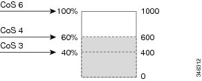
Figure 4. WTD and Queue Operation. The following figure shows an example of WTD operating on a queue whose size is 1000 frames. Three drop percentages are configured: 40 percent (400 frames), 60 percent (600 frames), and 100 percent (1000 frames). These percentages indicate that up to 400 frames can be queued at the 40-percent threshold, up to 600 frames at the 60-percent threshold, and up to 1000 frames at the 100-percent threshold.In the example, CoS value 6 has a greater importance than the other CoS values, and is assigned to the 100-percent drop threshold (queue-full state). CoS values 4 is assigned to the 60-percent threshold, and CoS values 3 is assigned to the 40-percent threshold. All of these threshold values are assigned using the queue-limit cos command.
Assuming the queue is already filled with 600 frames, and a new frame arrives. It contains CoS value 4 and is subjected to the 60-percent threshold. If this frame is added to the queue, the threshold will be exceeded, so the switch drops it.
Related Tasks
Related References
Weighted Tail Drop Default Values
The following are the Weighted Tail Drop (WTD) default values and the rules for configuring WTD threshold values.
- If you configure less than three queue-limit percentages for WTD, then WTD default values are assigned to these thresholds.
- If 3 different WTD thresholds are configured, then the queues are programmed as configured.
- If 2 WTD thresholds are configured, then the maximum value percentage will be 400.
- If a WTD single threshold is configured as x, then the maximum value percentage will be 400.
Priority Queues
Each port supports eight egress queues, of which two can be given a priority.
You use the priority level policy class-map command to configure the priority for two classes. One of the classes has to be configured with a priority queue level 1, and the other class has to be configured with a priority queue level 2. Packets on these two queues are subjected to less latency with respect to other queues.
Related Tasks
Queue Buffer
Each 1-gigabit port on the switch is allocated 168 buffers for a wireless port and 300 buffers for a wired port. Each 10-gigabit port is allocated 1800 buffers. At boot time, when there is no policy map enabled on the wired port, there are two queues created by default. Wired ports can have a maximum of 8 queues configured using MQC-based policies. The following table shows which packets go into which one of the queues:
Table 8 DSCP, Precedence, and CoS - Queue Threshold Mapping Table DSCP, Precedence or CoS
Queue
Threshold
Control Packets
0
2
Rest of Packets
1
2
NoteYou can guarantee the availability of buffers, set drop thresholds, and configure the maximum memory allocation for a queue. You use the queue-buffers policy-map class command to configure the queue buffers. You use the queue-limit policy-map class command to configure the maximum thresholds.
There are two types of buffer allocations: hard buffers, which are explicitly reserved for the queue, and soft buffers, which are available for other ports when unused by a given port.
For the wireless port default, Queue 0 will be given 40 percent of the buffers that are available for the interface as hard buffers, that is 67 buffers are allocated for Queue 0 in the context of 1-gigabit ports. The soft maximum for this queue is set to 268 (calculated as 67 * 400/100) for 1-gigabit ports, where 400 is the default maximum threshold that is configured for any queue.
For the wired port default, Queue 0 will be given 40 percent of the buffers that are available for the interface as hard buffers, that is 120 buffers are allocated for Queue 0 in the context of 1-gigabit ports, and 720 buffers in the context of 10-gigabit ports. The soft maximum for this queue is set to 480 (calculated as 120 * 400/100) for 1-gigabit ports and 2880 for 10-gigabit ports, where 400 is the default maximum threshold that is configured for any queue.
Queue 1 does not have any hard buffers allocated. The default soft buffer limit is set to 400 (which is the maximum threshold). The threshold would determine the maximum number of soft buffers that can be borrowed from the common pool.
Queue Buffer Allocation
The buffer allocation to any queue can be tuned using the queue-buffers ratio policy-map class configuration command.
Related Tasks
Related References
Dynamic Threshold and Scaling
Traditionally, reserved buffers are statically allocated for each queue. No matter whether the queue is active or not, its buffers are held up by the queue. In addition, as the number of queues increases, the portion of the reserved buffers allocated for each queue can become smaller and smaller. Eventually, a situation may occur where there are not enough reserved buffers to support a jumbo frame for all queues.
The switch supports Dynamic Thresholding and Scaling (DTS), which is a feature that provides a fair and efficient allocation of buffer resources. When congestion occurs, this DTS mechanism provides an elastic buffer allocation for the incoming data based on the occupancy of the global/port resources. Conceptually, DTS scales down the queue buffer allocation gradually as the resources are used up to leave room for other queues, and vice versa. This flexible method allows the buffers to be more efficiently and fairly utilized.
As mentioned in the previous sections, there are two limits configured on a queue—a hard limit and a soft limit.
Hard limits are not part of DTS. These buffers are available only for that queue. The sum of the hard limits should be less than the globally set up hard maximum limit. The global hard limit configured for egress queuing is currently set to 5705. In the default scenario when there are no MQC policies configured, the 24 1-gigabit ports would take up 24 * 67 = 1608, and the 4 10-gigabit ports would take up 4 * 720 = 2880, for a total of 4488 buffers, allowing room for more hard buffers to be allocated based upon the configuration.
Soft limit buffers participate in the DTS process. Additionally, some of the soft buffer allocations can exceed the global soft limit allocation. The global soft limit allocation for egress queuing is currently set to 7607. The sum of the hard and soft limits add up to 13312, which in turn translates to 3.4 MB. Because the sum of the soft buffer allocations can exceed the global limit, it allows a specific queue to use a large number of buffers when the system is lightly loaded. The DTS process dynamically adjusts the per-queue allocation as the system becomes more heavily loaded.
Queuing in Wireless
Queuing in the wireless component is performed based on the port policy and is applicable only in the downstream direction. The wireless module supports the following four queues:
- Voice—This is a strict priority queue. Represented by Q0, this queue processes control traffic and multicast or unicast voice traffic. All control traffic (such as CAPWAP packets) is processed through the voice queue. The QoS module uses a different threshold within the voice queue to process control and voice packets to ensure that control packets get higher priority over other non-control packets.
- Video—This is a strict priority queue. Represented by Q1, this queue processes multicast or unicast video traffic.
- Data NRT—Represented by Q2, this queue processes all non-real-time unicast traffic.
- Multicast NRT—Represented by Q3, this queue processes Multicast NRT traffic. Any traffic that does not match the traffic in Q0, Q1, or Q2 is processed through Q3.
NoteBy default, the queues Q0 and Q1 are not enabled.
NoteA weighted round-robin policy is applied for traffic in the queues Q2 and Q3.
For upstream direction only one queue is available. Port and radio policies are applicable only in the downstream direction.
NoteThe wired ports support eight queues.
Trust Behavior
Trust Behavior for Wired and Wireless Ports
For wired or wireless ports that are connected to the switch (end points such as IP phones, laptops, cameras, telepresence units, or other devices), their DSCP, precedence, or CoS values coming in from these end points are trusted by the switch and therefore are retained in the absence of any explicit policy configuration.
This trust behavior is applicable to both upstream and downstream QoS.
The packets are enqueued to the appropriate queue per the default initial configuration. No priority queuing at the switch is done by default. This is true for unicast and multicast packets.
In scenarios where the incoming packet type differs from the outgoing packet type, the trust behavior and the queuing behavior are explained in the following table. Note that the default trust mode for a port is DSCP based. The trust mode ‘falls back’ to CoS if the incoming packet is a pure Layer 2 packet. You can also change the trust setting from DSCP to CoS. This setting change is accomplished by using an MQC policy that has a class default with a 'set cos cos table default default-cos' action, where default-cos is the name of the table map created (which only performs a default copy).
Table 9 Trust and Queueing BehaviorIncoming Packet
Outgoing Packet
Trust Behavior
Queuing Behavior
Layer 3
Layer 3
Preserve DSCP/Precedence
Based on DSCP
Layer 2
Layer 2
Not applicable
Based on CoS
Tagged
Tagged
Preserve DSCP and CoS
Based on DSCP (trust DSCP takes precedence)
Layer 3
Tagged
Preserve DSCP, CoS is set to 0
Based on DSCP
The Cisco IOS XE 3.2 Release supported different trust defaults for wired and wireless ports. The trust default for wired ports was the same as for this software release. For wireless ports, the default system behavior was non-trust, which meant that when the switch came up, all markings for the wireless ports were defaulted to zero and no traffic received priority treatment. For compatibility with an existing wired switch, all traffic went to the best-effort queue by default. The access point performed priority queuing by default. In the downstream direction, the access point maintained voice, video, best-effort, and background queues for queuing. The access selected the queuing strategy based on the 11e tag information. By default, the access point treated all wireless packets as best effort.
The default trust behavior in the case of wireless ports could be changed by using the qos wireless default untrust command.
Note
If you upgrade from Cisco IOS XE 3.2 SE Release to a later release, the default behavior of the wireless traffic is still untrusted. In this situation, you can use the no qos wireless-default untrust command to enable trust behavior for wireless traffic. However, if you install Cisco IOS XE 3.3 SE or a later release on the switch, the default QoS behavior for wireless traffic is trust. Starting with Cisco IOS XE 3.3 SE Release and later, the packet markings are preserved in both egress and ingress directions for new installations (not upgrades) for wireless traffic.
Related Tasks
Related References
Port Security on a Trusted Boundary for Cisco IP Phones
In a typical network, you connect a Cisco IP Phone to a switch port and cascade devices that generate data packets from the back of the telephone. The Cisco IP Phone guarantees the voice quality through a shared data link by marking the CoS level of the voice packets as high priority (CoS = 5) and by marking the data packets as low priority (CoS = 0). Traffic sent from the telephone to the switch is typically marked with a tag that uses the 802.1Q header. The header contains the VLAN information and the class of service (CoS) 3-bit field, which is the priority of the packet.
For most Cisco IP Phone configurations, the traffic sent from the telephone to the switch should be trusted to ensure that voice traffic is properly prioritized over other types of traffic in the network. By using the trust device interface configuration command, you configure the switch port to which the telephone is connected to trust the traffic received on that port.
Note
The trust device device_type interface configuration command is only supported in an auto-QoS configuration, and not as a stand-alone command on the switch. When using the trust device device_type interface configuration command in an auto-QoS configuration, if the connected peer device is not a corresponding device (defined as a device matching your trust policy), both CoS and DSCP values are set to "0" and any input policy will not take effect.
With the trusted setting, you also can use the trusted boundary feature to prevent misuse of a high-priority queue if a user bypasses the telephone and connects the PC directly to the switch. Without trusted boundary, the CoS labels generated by the PC are trusted by the switch (because of the trusted CoS setting). By contrast, trusted boundary uses CDP to detect the presence of a Cisco IP Phone (such as the Cisco IP Phone 7910, 7935, 7940, and 7960) on a switch port. If the telephone is not detected, the trusted boundary feature disables the trusted setting on the switch port and prevents misuse of a high-priority queue. Note that the trusted boundary feature is not effective if the PC and Cisco IP Phone are connected to a hub that is connected to the switch.
Related Tasks
Wireless QoS Mobility
Wireless QoS mobility enables you to configure QoS policies so that the network provides the same service anywhere in the network. A wireless client can roam from one location to another and as a result the client can get associated to different access points associated with a different switch. Wireless client roaming can be classified into two types:
Note
The client policies must be available on all of the switches in the mobility group. The same SSID and port policy must be applied to all switches in the mobility group so that the clients get consistent treatment.Inter-Switch Roaming
When a client roams from one location to another, the client can get associated to access points either associated to the same switch (anchor switch) or a different switch (foreign switch). Inter-switch roaming refers to the scenario where the client gets associated to an access point that is not associated to the same device before the client roamed. The host device is now foreign to the device to which the client was initially anchored.
In the case of inter-switch roaming, the client QoS policy is always executed on the foreign controller. When a client roams from anchor switch to foreign switch, the QoS policy is uninstalled on the anchor switch and installed on the foreign switch. In the mobility handoff message, the anchor device passes the name of the policy to the foreign switch. The foreign switch should have a policy with the same name configured for the QoS policy to be applied correctly.
In the case of inter-switch roaming, all of the QoS policies are moved from the anchor device to the foreign device. While the QoS policies are in transition from the anchor device to the foreign device, the traffic on the foreign device is provided the default treatment. This is comparable to a new policy installation on the client target.
NoteIf the foreign device is not configured with the user-defined physical port policy, the default port policy is applicable to all traffic is routed through the NRT queue, except the control traffic which goes through RT1 queue. The network administrator must configure the same physical port policy on both the anchor and foreign devices symmetrically.
Intra-Switch Roaming
With intra-switch roaming, the client gets associated to an access point that is associated to the same switch before the client roamed, but this association to the device occurs through a different access point.
NoteQoS policies remain intact in the case of intra-switch roaming.
Precious Metal Policies for Wireless QoS
Wireless QoS is backward compatible with the precious metal policies offered by the unified wireless controller platforms. The precious metal policies are system-defined policies that are available on the controller.
The following policies are available:
These policies (also known as profiles) can be applied to a WLAN based on the traffic. We recommend the configuration using the Cisco IOS MQC configuration. The policies are available in the system based on the precious metal policy required.
Based on the policies applied, the 802.1p, 802.11e (WMM), and DSCP fields in the packets are affected. These values are preconfigured and installed when the switch is booted.
NoteUnlike the precious metal policies that were applicable in the Cisco Unified Wireless controllers, the attributes rt-average-rate, nrt-average-rate, and peak rates are not applicable for the precious metal policies configured on this switch platform.
Related Tasks
Standard QoS Default Settings
Default Wired QoS Configuration
There are two queues configured by default on each wired interface on the switch. All control traffic traverses and is processed through queue 0. All other traffic traverses and is processed through queue 1.
DSCP Maps
Default CoS-to-DSCP Map
You use the CoS-to-DSCP map to map CoS values in incoming packets to a DSCP value that QoS uses internally to represent the priority of the traffic. The following table shows the default CoS-to-DSCP map. If these values are not appropriate for your network, you need to modify them.
Table 10 Default CoS-to-DSCP MapDefault IP-Precedence-to-DSCP Map
You use the IP-precedence-to-DSCP map to map IP precedence values in incoming packets to a DSCP value that QoS uses internally to represent the priority of the traffic. The following table shows the default IP-precedence-to-DSCP map. If these values are not appropriate for your network, you need to modify them.
Table 11 Default IP-Precedence-to-DSCP MapDefault Wireless QoS Configuration
The ports on the switch do not distinguish between wired or wireless physical ports. Depending on the kind of device associated to the switch, the policies are applied. For example, when an access point is connected to a switch port, the switch detects it as a wireless device and applies the default hierarchical policy which is in the format of a parent-child policy. This policy is an hierarchical policy. The parent policy cannot be modified but the child policy (port-child policy) can be modified to suite the QoS configuration. The switch is preconfigured with a default class map and a policy map.
Restrictions for QoS on Wired Targets
A target is an entity where a policy is applied. You can apply a policy to either a wired or wireless target. A wired target can be either a port or VLAN. A wireless target can be either a port, radio, SSID, or client. Only port, SSID, and client policies are user configurable. Radio polices are not user configurable. Wireless QoS policies for port, radio, SSID, and client are applied in the downstream direction, and for upstream only SSID and client targets are supported. Downstream indicates that traffic is flowing from the switch to the wireless client. Upstream indicates that traffic is flowing from wireless client to the switch.
The following are restrictions for applying QoS features on the switch for the wired target:
- A maximum of 8 queuing classes are supported on the switch port for the wired target.
- A maximum of 63 policers are supported per policy on the wired port for the wired target.
- No more than two levels are supported in a QoS hierarchy.
- In a hierarchical policy, overlapping actions between parent and child are not allowed, except when a policy has the port shaper in the parent and queueing features in the child policy.
- A QoS policy cannot be attached to any EtherChannel interface.
- Policing in both the parent and child is not supported in a QoS hierarchy.
- Marking in both the parent and child is not supported in a QoS hierarchy.
- A mixture of queue limit and queue buffer in the same policy is not supported.
Note
The queue-limit percent is not supported on the switch because the queue-buffer command handles this functionality. Queue limit is only supported with the DSCP and CoS extensions.
- The classification sequence for all wired queuing-based policies should be the same across all wired upstream ports (10-Gigabit Ethernet), and the same for all downstream wired ports (1-Gigabit Ethernet).
- Empty classes are not supported.
- Class-maps with empty actions are not supported.
- A maximum of 256 classes are supported per policy on the wired port for the wired target.
- The actions under a policer within a policy map have the following restrictions:
- Classification counters have the following specific restrictions:
- Classification counters count packets instead of bytes.
- Only QoS configurations with marking or policing trigger the classification counter.
- The classification counter is not port based. This means that the classification counter aggregates all packets belonging to the same class of the same policy which attach to different interfaces.
- As long as there is policing or marking action in the policy, the class-default will have classification counters.
- When there are multiple match statements in a class, then the classification counter only shows the traffic counter for one of the match statements.
- Table maps have the following specific restrictions:
- Hierarchical policies are required for the following:
- For ports with wired targets, these are the only supported hierarchical policies:
- Police chaining in the same policy is unsupported, except for wireless client.
- Hierarchical queueing is unsupported in the same policy (port shaper is the exception).
- The trust device device_type interface configuration command is only supported in an auto-QoS configuration, and not as a stand-alone command on the switch. When using the trust device device_type interface configuration command in an auto-QoS configuration, if the connected peer device is not a corresponding device (defined as a device matching your trust policy), both CoS and DSCP values are set to "0" and any input policy will not take effect.
The following are restrictions for applying QoS features on the VLAN to the wired target:
The following are restrictions and considerations for applying QoS features on EtherChannel and channel member interfaces:
- QoS is not supported on an EtherChannel interface.
- QoS is supported on EtherChannel member interfaces in both ingress and egression directions. All EtherChannel members must have the same QoS policy applied. If the QoS policy is not the same, each individual policy on the different link acts independently.
- On attaching a service policy to channel members, the following warning message appears to remind the user to make sure the same policy is attached to all ports in the EtherChannel: ' Warning: add service policy will cause inconsistency with port xxx in ether channel xxx. '.
- Auto QoS is not supported on EtherChannel members.
Note
On attaching a service policy to an EtherChannel, the following message appears on the console: ' Warning: add service policy will cause inconsistency with port xxx in ether channel xxx. '. This warning message should be expected. This warning message is a reminder to attach the same policy to other ports in the same EtherChannel. The same message will be seen during boot up. This message does not mean there is a discrepancy between the EtherChannel member ports.Restrictions for QoS on Wireless Targets
General Restrictions
A target is an entity where a policy is applied. You can apply a policy to either a wired or wireless target. A wired target can be either a port or VLAN. A wireless target can be either a port, radio, SSID, or client. Only port, SSID, and client policies are user configurable. Radio polices are not user configurable. Wireless QoS policies for port, radio, SSID, and client are applied in the downstream direction, and for upstream only SSID and client targets are supported. Downstream indicates that traffic is flowing from the switch to the wireless client. Upstream indicates that traffic is flowing from wireless client to the switch.
- Only port, SSID, and client (using AAA and Cisco IOS command-line interface) policies are user-configurable. Radio policies are set by the wireless control module and are not user-configurable.
- Port and radio policies are applicable only in the downstream direction.
- SSID and client support non-queuing policies in the upstream direction. SSID and client targets can be configured with marking and policing policies.
- One policy per target per direction is supported.
Wireless QoS Restrictions on Ports
The following are restrictions for applying QoS features on a wireless port target:
- All wireless ports have similar parent policy with one class-default and one action shape under class-default. Shape rates are dependent on the 802.11a/b/g/ac bands.
- You can create a maximum of four classes in a child policy by modifying the port_chlid_policy.
- If there are four classes in the port_child_policy at the port level, one must be a non-client-nrt class and one must be class-default.
- No two classes can have the same priority level. Only priority level 1 (for voice traffic and control traffic) and 2 (for video) are supported.
- Priority is not supported in the multicast NRT class (non-client-nrt class) and class-default.
- If four classes are configured, two of them have to be priority classes. If only three classes are configured, at least one of them should be a priority class. If three classes are configured and there is no non-client-nrt class, both priority levels must be present.
- Only match DSCP is supported.
- The port policy applied by the wireless control module cannot be removed using the CLI.
- Both priority rate and police CIR (using MQC) in the same class is unsupported.
- Queue limit (which is used to configure Weighted Tail Drop) is unsupported.
Wireless QoS Restrictions on SSID
The following are restrictions for applying QoS features on SSID:
- One table map is supported at the ingress policy.
- Table maps are supported for the parent class-default only. Up to two table maps are supported in the egress direction and three table-maps can be configured when a QoS group is involved.
Note
Table-maps are not supported at the client targets.
- If a wireless port has a default policy with only two queues (one for multicast-NRT, one for class-default), the policy at SSID level cannot have voice and video class in the egress direction.
- Policing without priority is not supported in the egress direction.
- Priority configuration at the SSID level is used only to configure the RT1 and RT2 policers (AFD for policer). Priority configuration does not include the shape rate. Therefore, priority is restricted for SSID policies without police.
- The mapping in the DSCP2DSCP and COS2COS table should be based on the classification function for the voice and video classes in the port level policy.
- No action is allowed under the class-default of a child policy.
- For a flat policy (non hierarchical), in the ingress direction, the policy configuration must be a set (table map) or policing or both.
Wireless QoS Restrictions on Clients
The following are restrictions for applying QoS policies on client targets:
- Queuing is not supported.
- Attaching, removing, or modifying client policies on a WLAN in the enabled state is not supported. You must shut down the WLAN to apply, remove, or modify a policy.
- Table-map configuration is not supported for client targets.
- Policing and set configured together in class-default is blocked in both the upstream and downstream direction:
policy-map foo class class-default police X set dscp Y- Child policy is not supported under class-default if the parent policy contains other user-defined class maps in it.
- Hierarchical client polies are only supported in the egress direction.
- For flat egress client policy, policing in class-default and marking action in other classes are not supported.
- Restrictions for ACLs:
- All the filters in classes in a policy map for client policy must have the same attributes. Filters matching on protocol-specific attributes such as IPv4 or IPv6 addresses are considered as different attribute sets.
- For filters matching on ACLs, all ACEs (Access Control Entry) in the access list should have the same type and number of attributes. For example, the following is an invalid access list as they match on different attributes:
policy map foo class acl-101 (match on 3 tuple) police X class acl-102 (match on 5 tuple) police Y- For filters matching on marking attributes, all filters in the policy-map must match on the same marking attribute. For example, If filter matches on DSCP, then all filters in the policy must match on DSCP.
- ACL matching on port ranges and subnet are only supported in ingress direction.
- If an ingress SSID policy is configured along with an ingress client policy matching ACLs with port ranges, the SSID policy takes precedence over the client policy. As a result, the client policy will not take effect.
Related Concepts
Related References
How to Configure QoS
Configuring Class, Policy, and Table Maps
Creating a Traffic Class (CLI)
To create a traffic class containing match criteria, use the class-map command to specify the traffic class name, and then use the following match commands in class-map configuration mode, as needed.
Before You BeginSUMMARY STEPSAll match commands specified in this configuration task are considered optional, but you must configure at least one match criterion for a class.
2. class-map {class-map name | match-any}
3. match access-group {index number | name}
4. match class-map class-map name
5. match cos cos value
6. match dscp dscp value
7. match ip {dscp dscp value | precedence precedence value }
8. match non-client-nrt
9. match qos-group qos group value
10. match vlan vlan value
11. match wlan user-priority wlan value
12. end
DETAILED STEPS
Configure the policy map.
Related Concepts
Related References
Creating a Traffic Policy (CLI)
SUMMARY STEPSTo create a traffic policy, use the policy-map global configuration command to specify the traffic policy name.
The traffic class is associated with the traffic policy when the class command is used. The class command must be entered after you enter the policy map configuration mode. After entering the class command, the switch is automatically in policy map class configuration mode, which is where the QoS policies for the traffic policy are defined.
The following policy map class-actions are supported:
- admit—Admits the request for Call Admission Control (CAC).
- bandwidth—Bandwidth configuration options.
- exit—Exits from the QoS class action configuration mode.
- no—Negates or sets default values for the command.
- police—Policer configuration options.
- priority—Strict scheduling priority configuration options for this class.
- queue-buffers—Queue buffer configuration options.
- queue-limit—Queue maximum threshold for Weighted Tail Drop (WTD) configuration options.
- service-policy—Configures the QoS service policy.
- set—Sets QoS values using the following options:
- shape—Traffic-shaping configuration options.
2. policy-map policy-map name
3. class {class-name | class-default}
4. admit
5. bandwidth {kb/s kb/s value | percent percentage | remaining {percent | ratio}}
6. exit
7. no
8. police {target_bit_rate | cir | rate}
9. priority {kb/s | level level value | percent percentage value}
10. queue-buffers ratio ratio limit
11. queue-limit {packets | cos | dscp | percent}
12. service-policy policy-map name
13. set {cos | dscp | ip | precedence | qos-group | wlan}
14. shape average {target _bit_rate | percent}
15. end
DETAILED STEPSWhat to Do Next
Command or Action Purpose
Step 1 configure terminal
Example:Switch# configure terminalStep 2 policy-map policy-map name
Example:Switch(config)# policy-map test_2000 Switch(config-pmap)#Enters policy map configuration mode.
Creates or modifies a policy map that can be attached to one or more interfaces to specify a service policy.
Step 3 class {class-name | class-default}
Example:Switch(config-pmap)# class test_1000 Switch(config-pmap-c)#Specifies the name of the class whose policy you want to create or change.
You can also create a system default class for unclassified packets.
Step 4 admit
Example:Switch(config-pmap-c)# admit cac wmm-tspec Switch(config-pmap-c)#(Optional) Admits the request for Call Admission Control (CAC). For a more detailed example of this command and its usage, see Configuring Call Admission Control (CLI).
Note This command only configures CAC for wireless QoS.
Step 5 bandwidth {kb/s kb/s value | percent percentage | remaining {percent | ratio}}
Example:Switch(config-pmap-c)# bandwidth 50 Switch(config-pmap-c)#(Optional) Sets the bandwidth using one of the following:
- kb/s—Kilobits per second, enter a value between 20000 and 10000000 for Kb/s.
- percent—Enter the percentage of the total bandwidth to be used for this policy map.
- remaining—Enter the percentage ratio of the remaining bandwidth.
For a more detailed example of this command and its usage, see Configuring Bandwidth (CLI).
Step 6 exit
Example:Switch(config-pmap-c)# exit Switch(config-pmap-c)#(Optional) Exits from QoS class action configuration mode.
Step 7 no
Example:Switch(config-pmap-c)# no Switch(config-pmap-c)#(Optional) Negates the command.
Step 8 police {target_bit_rate | cir | rate}
Example:Switch(config-pmap-c)# police 100000 Switch(config-pmap-c)#(Optional) Configures the policer:
- target_bit_rate—Enter the bit rate per second, enter a value between 8000 and 10000000000.
- cir—Committed Information Rate
- rate—Specify police rate, PCR for hierarchical policies or SCR for single-level ATM 4.0 policer policies.
For a more detailed example of this command and its usage, see Configuring Police (CLI).
Step 9 priority {kb/s | level level value | percent percentage value}
Example:Switch(config-pmap-c)# priority percent 50 Switch(config-pmap-c)#(Optional) Sets the strict scheduling priority for this class. Command options include:
- kb/s—Kilobits per second, enter a value between 1 and 2000000.
- level—Establishes a multi-level priority queue. Enter a value (1 or 2).
- percent—Enter a percent of the total bandwidth for this priority.
For a more detailed example of this command and its usage, see Configuring Priority (CLI).
Step 10 queue-buffers ratio ratio limit
Example:Switch(config-pmap-c)# queue-buffers ratio 10 Switch(config-pmap-c)#(Optional) Configures the queue buffer for the class. Enter the queue buffers ratio limit (0 to 100).
For a more detailed example of this command and its usage, see Configuring Queue Buffers (CLI).
Step 11 queue-limit {packets | cos | dscp | percent}
Example:Switch(config-pmap-c)# queue-limit cos 7 percent 50 Switch(config-pmap-c)#(Optional) Specifies the queue maximum threshold for the tail drop:
- packets—Packets by default, enter a value between 1 to 2000000.
- cos—Enter the parameters for each COS value.
- dscp—Enter the parameters for each DSCP value.
- percent—Enter the percentage for the threshold.
For a more detailed example of this command and its usage, see Configuring Queue Limits (CLI).
Step 12 service-policy policy-map name
Example:Switch(config-pmap-c)# service-policy test_2000 Switch(config-pmap-c)#(Optional) Configures the QoS service policy.
Step 13 set {cos | dscp | ip | precedence | qos-group | wlan}
Example:Switch(config-pmap-c)# set cos 7 Switch(config-pmap-c)#(Optional) Sets the QoS values. Possible QoS configuration values include:
Step 14 shape average {target _bit_rate | percent}
Example:Switch(config-pmap-c) #shape average percent 50 Switch(config-pmap-c) #For a more detailed example of this command and its usage, see Configuring Shaping (CLI).
Step 15 end
Example:Switch(config-pmap-c) #end Switch(config-pmap-c) #Saves the configuration changes.
Configure the interface.
Related Concepts
Configuring Client Policies (GUI)
Step 1 Choose . Step 2 Expand the QoS node by clicking on the left pane and choose QOS-Policy. The QOS-Policy page is displayed.
Step 3 Click Add New to create a new QoS Policy. The Create QoS Policy page is displayed.
Step 4 Select Client from the Policy Type drop-down menu. Step 5 Select the direction into which the policy needs to be applied from the Policy Direction drop-down menu. The available options are:
Step 6 Specify a policy name in the Policy Name text box. Step 7 Provide a description to the policy in the Description text box. Step 8 (Optional)Configure the default voice or video configuration parameters by checking the Enable Voice or Enable Video checkbox. The following options are available:
- Trust—Specify the classification type behavior on this policy. The options available are:
- DSCP—Assigns a label to indicate the given quality of service. The range is from 0 to 63.
- User Priority—This option is available when the Policy Direction is ingress. Enter the 802.11e user priority. The range is from 0 to 7.
- COS—This option is available when the Policy Direction is egress. Matches IEEE 802.1Q class of service. The range is from 0 to 7.
- Mark—Specify the marking label for each packet. The following options are available:
- Police(kbps)—Specify the policing rate in kbps.
Note The marking and policing options are optional.
Step 9 Specify the Class-default parameters. The following options are available:
Step 10 (Optional)To configure user defined classes, check the User Defined Classes checkbox. The following options are available:
- Trust—Specify the classification type behavior on this policy.
- DSCP—Assigns a label to indicate the given quality of service. The range is from 0 to 63.
- User Priority—This option is available when the Policy Direction is ingress. Enter the 802.11e user priority. The range is from 0 to 7.
- COS—This option is available when the Policy Direction is egress. Matches IEEE 802.1Q class of service. The range is from 0 to 7.
- Mark—Specify the marking label for each packet. The following options are available:
Step 11 Click Add to add the policy.
Related References
Configuring Class-Based Packet Marking (CLI)
This procedure explains how to configure the following class-based packet marking features on your switch:
Before You BeginSUMMARY STEPSYou should have created a class map and a policy map before beginning this procedure.
2. policy-map policy name
3. class class name
4. set cos {cos value | cos table table-map name | dscp table table-map name | precedence table table-map name | qos-group table table-map name | wlan user-priority table table-map name}
5. set dscp {dscp value | default | dscp table table-map name | ef | precedence table table-map name | qos-group table table-map name | wlan user-priority table table-map name}
6. set ip {dscp | precedence}
7. set precedence {precedence value | cos table table-map name | dscp table table-map name | precedence table table-map name | qos-group table table-map name}
8. set qos-group {qos-group value | dscp table table-map name | precedence table table-map name}
9. set wlan user-priority {wlan user-priority value | cos table table-map name | dscp table table-map name | qos-group table table-map name | wlan table table-map name}
10. end
11. show policy-map
DETAILED STEPSWhat to Do Next
Command or Action Purpose
Step 1 configure terminal
Example:Switch# configure terminalStep 2 policy-map policy name
Example:Switch(config)# policy-map policy1 Switch(config-pmap)#Enters policy map configuration mode.
Creates or modifies a policy map that can be attached to one or more interfaces to specify a service policy.
Step 3 class class name
Example:Switch(config-pmap)# class class1 Switch(config-pmap-c)#Enters policy class map configuration mode. Specifies the name of the class whose policy you want to create or change.
Command options for policy class map configuration mode include the following:
- admit—Admits the request for Call Admission Control (CAC).
- bandwidth—Bandwidth configuration options.
- exit—Exits from the QoS class action configuration mode.
- no—Negates or sets default values for the command.
- police—Policer configuration options.
- priority—Strict scheduling priority configuration options for this class.
- queue-buffers—Queue buffer configuration options.
- queue-limit—Queue maximum threshold for Weighted Tail Drop (WTD) configuration options.
- service-policy—Configures the QoS service policy.
- set—Sets QoS values using the following options:
- shape—Traffic-shaping configuration options.
Note This procedure describes the available configurations using set command options. The other command options (admit, bandwidth, etc.) are described in other sections of this guide. Although this task lists all of the possible set commands, only one set command is supported per class.
Step 4 set cos {cos value | cos table table-map name | dscp table table-map name | precedence table table-map name | qos-group table table-map name | wlan user-priority table table-map name}
Example:Switch(config-pmap)# set cos 5 Switch(config-pmap)#(Optional) Sets the specific IEEE 802.1Q Layer 2 CoS value of an outgoing packet. Values are from 0 to7.
You can also set the following values using the set cos command:
- cos table—Sets the CoS value based on a table map.
- dscp table—Sets the code point value based on a table map.
- precedence table—Sets the code point value based on a table map.
- qos-group table—Sets the CoS value from QoS group based on a table map.
- wlan user-priority table—Sets the CoS value from the WLAN user priority based on a table map.
Step 5 set dscp {dscp value | default | dscp table table-map name | ef | precedence table table-map name | qos-group table table-map name | wlan user-priority table table-map name}
Example:Switch(config-pmap)# set dscp af11 Switch(config-pmap)#(Optional) Sets the DSCP value.
In addition to setting specific DSCP values, you can also set the following using the set dscp command:
- default—Matches packets with default DSCP value (000000).
- dscp table—Sets the packet DSCP value from DSCP based on a table map.
- ef—Matches packets with EF DSCP value (101110).
- precedence table—Sets the packet DSCP value from precedence based on a table map.
- qos-group table—Sets the packet DSCP value from a QoS group based upon a table map.
- wlan user-priority table—Sets the packet DSCP value based upon a WLAN user-priority based upon a table map.
Step 6 set ip {dscp | precedence}
Example:Switch(config-pmap)# set ip dscp c3 Switch(config-pmap)#(Optional) Sets IP specific values. These values are either IP DSCP or IP precedence values.
You can set the following values using the set ip dscp command:
- dscp value—Sets a specific DSCP value.
- default—Matches packets with default DSCP value (000000).
- dscp table—Sets the packet DSCP value from DSCP based on a table map.
- ef—Matches packets with EF DSCP value (101110).
- precedence table—Sets the packet DSCP value from precedence based on a table map.
- qos-group table—Sets the packet DSCP value from a QoS group based upon a table map.
- wlan user-priority table—Sets the packet DSCP value based upon a WLAN user-priority based upon a table map.
You can set the following values using the set ip precedence command:
- precedence value—Sets the precedence value (from 0 to 7) .
- cos table—Sets the packet precedence value from Layer 2 CoS based on a table map.
- dscp table—Sets the packet precedence from DSCP value based on a table map.
- precedence table—Sets the precedence value from precedence based on a table map
- qos-group table—Sets the precedence value from a QoS group based upon a table map.
Step 7 set precedence {precedence value | cos table table-map name | dscp table table-map name | precedence table table-map name | qos-group table table-map name}
Example:Switch(config-pmap)# set precedence 5 Switch(config-pmap)#(Optional) Sets precedence values in IPv4 and IPv6 packets.
You can set the following values using the set precedence command:
- precedence value—Sets the precedence value (from 0 to 7) .
- cos table—Sets the packet precedence value from Layer 2 CoS on a table map.
- dscp table—Sets the packet precedence from DSCP value on a table map.
- precedence table—Sets the precedence value from precedence based on a table map.
- qos-group table—Sets the precedence value from a QoS group based upon a table map.
Step 8 set qos-group {qos-group value | dscp table table-map name | precedence table table-map name}
Example:Switch(config-pmap)# set qos-group 10 Switch(config-pmap)#(Optional) Sets QoS group values. You can set the following values using this command:
Step 9 set wlan user-priority {wlan user-priority value | cos table table-map name | dscp table table-map name | qos-group table table-map name | wlan table table-map name}
Example:Switch(config-pmap)# set wlan user-priority 1 Switch(config-pmap)#(Optional) Sets the WLAN user priority value. You can set the following values using this command:
- wlan user-priority value—A value between 0 to 7.
- cos table—Sets the WLAN user priority value from CoS based on a table map.
- dscp table—Sets the WLAN user priority value from DSCP based on a table map.
- qos-group table—Sets the WLAN user priority value from QoS group based on a table map.
- wlan table—Sets the WLAN user priority value from the WLAN user priority based on a table map.
Step 10 end
Example:Switch(config-pmap)# end Switch#Saves configuration changes.
Step 11 show policy-map
Example:Switch# show policy-map(Optional) Displays policy configuration information for all classes configured for all service policies.
Attach the traffic policy to an interface using the service-policy command.
Configuring Class Maps for Voice and Video (CLI)
SUMMARY STEPS
1. configure terminal
2. class-map class-map-name
3. match dscp dscp-value-for-voice
4. end
5. configure terminal
6. class-map class-map-name
7. match dscp dscp-value-for-video
8. end
DETAILED STEPS
Command or Action Purpose
Step 1 configure terminal
Example:Switch# configure terminalEnters global configuration mode.
Step 2 class-map class-map-name
Example:Switch(config)# class-map voiceCreates a class map.
Step 3 match dscp dscp-value-for-voice
Example:Switch(config-cmap)# match dscp 46Matches the DSCP value in the IPv4 and IPv6 packets. Set this value to 46.
Step 4 end
Example:Switch(config)# endReturns to privileged EXEC mode. Alternatively, you can also press Ctrl-Z to exit global configuration mode.
Step 5 configure terminal
Example:Switch# configure terminalEnters global configuration mode.
Step 6 class-map class-map-name
Example:Switch(config)# class-map videoConfigures a class map.
Step 7 match dscp dscp-value-for-video
Example:Switch(config-cmap)# match dscp 34Matches the DSCP value in the IPv4 and IPv6 packets. Set this value to 34.
Step 8 end
Example:Switch(config)# endReturns to privileged EXEC mode. Alternatively, you can also press Ctrl-Z to exit global configuration mode.
Attaching a Traffic Policy to an Interface (CLI)
After the traffic class and traffic policy are created, you must use the service-policy interface configuration command to attach a traffic policy to an interface, and to specify the direction in which the policy should be applied (either on packets coming into the interface or packets leaving the interface).
Before You BeginSUMMARY STEPSA traffic class and traffic policy must be created before attaching a traffic policy to an interface.
2. interface type
3. service-policy {input policy-map | output policy-map }
4. end
5. show policy map
DETAILED STEPSWhat to Do Next
Command or Action Purpose
Step 1 configure terminal
Example:Switch# configure terminalStep 2 interface type
Example:Switch(config)# interface GigabitEthernet1/0/1 Switch(config-if)#Enters interface configuration mode and configures an interface.
Command parameters for the interface configuration include:
- Auto Template— Auto-template interface
- Capwap—CAPWAP tunnel interface
- GigabitEthernet—Gigabit Ethernet IEEE 802
- GroupVI—Group virtual interface
- Internal Interface— Internal interface
- Loopback—Loopback interface
- Null—Null interface
- Port-channel—Ethernet Channel of interface
- TenGigabitEthernet—10-Gigabit Ethernet
- Tunnel—Tunnel interface
- Vlan—Catalyst VLANs
- Range—Interface range
Step 3 service-policy {input policy-map | output policy-map }
Example:Switch(config-if)# service-policy output policy_map_01 Switch(config-if)#Attaches a policy map to an input or output interface. This policy map is then used as the service policy for that interface.
In this example, the traffic policy evaluates all traffic leaving that interface.
Step 4 end
Example:Switch(config-if)# end Switch#Saves configuration changes.
Step 5 show policy map
Example:Switch# show policy map(Optional) Displays statistics for the policy on the specified interface.
Proceed to attach any other traffic policy to an interface, and to specify the direction in which the policy should be applied.
Related Concepts
Configuring SSID Policies (GUI)
Step 1 Choose . Step 2 Expand the QoS node by clicking on the left pane and choose QOS-Policy. The Create QoS Policy page is displayed.
Step 3 Click Add New to create a new QoS Policy. The QoS Policy page is displayed.
Step 4 Select SSID from the Policy Type drop-down menu. Step 5 Select the direction into which the policy needs to be applied from the Policy Direction drop-down list. The available options are:
Note Voice and video configurations are available only in the egress direction.
Note When creating an egress SSID policy for voice and video classes, if the port_child_policy is already configured with voice and video classes having priority level, the existing port_child_policy is used. If a port_child_policy does not exist with voice and video classes, the switch will create voice and video classes with priority levels 1 and 2 under port_child_policy for voice and video traffic.
Step 6 Specify a policy name in the Policy Name text box. Step 7 Provide a description to the policy in the Description text box. Step 8 Select the trust parameter from the Trust drop-down list. The following options are available:
- DSCP— Assigns a label to indicate the given quality of service as DSCP.
- COS—Matches IEEE 802.1Q class of service. This option is not available when the Policy Direction is engres.
- User Priority—Enter the 802.11e user priority. This option is not available when the Policy Direction is engres.
- None—This option is available when the Policy Direction is egress. This option is available only for egress policies.
Step 9 If you chose Egress policy above, the following options are available:
- Bandwidth—Specifies the bandwidth rate. The following options are available:
- Rate—Specifies the bandwidth in kbps. Enter a value in kbps in the Value field.
- Remaining Ratio—Specifies the bandwidth in BRR (bandwidth remaining ratio). Enter the percentage in the Percent field.
.
Note If you choose the Rate option for the Bandwidth parameter, this value must be greater than the sum of the policing values for voice and video traffic.
- Enable Voice—Click on the Enable Voice checkbox to enable voice traffic on this policy. Specify the following properties:
- Enable Video—Check the Enable Video checkbox to enable video traffic on this policy. Specify the following properties:
Step 10 Click Apply.
Applying an SSID or Client Policy on a WLAN (CLI)
SUMMARY STEPS
1. configure terminal
2. wlan profile-name
3. service-policy [ input | output ] policy-name
4. service-policy client [ input | output ] policy-name
5. end
DETAILED STEPS
Command or Action Purpose
Step 1 configure terminal
Example:Switch# configure terminalEnters global configuration mode.
Step 2 wlan profile-name
Example:Switch# wlan test4Enters the WLAN configuration submode. The profile-name is the profile name of the configured WLAN.
Step 3 service-policy [ input | output ] policy-name
Example:Switch(config-wlan)# service-policy input policy-map-ssidStep 4 service-policy client [ input | output ] policy-name
Example:Switch(config-wlan)# service-policy client input policy-map-clientStep 5 end
Example:Switch(config)# endReturns to privileged EXEC mode. Alternatively, you can also press Ctrl-Z to exit global configuration mode.
Classifying, Policing, and Marking Traffic on Physical Ports by Using Policy Maps (CLI)
You can configure a nonhierarchical policy map on a physical port that specifies which traffic class to act on. Actions supported are remarking and policing.
Before You BeginSUMMARY STEPSYou should have already decided upon the classification, policing, and marking of your network traffic by policy maps prior to beginning this procedure.
2. class-map {class-map name | match-any }
3. match access-group { access list index | access list name }
5. class {class-map-name | class-default}
6. set {cos | dscp | ip | precedence | qos-group | wlan user-priority}
7. police {target_bit_rate | cir | rate }
11. service-policy input policy-map-name
13. show policy-map [policy-map-name [class class-map-name]]
DETAILED STEPSWhat to Do Next
Command or Action Purpose
Step 1 configure terminal
Example:Switch# configure terminalStep 2 class-map {class-map name | match-any }
Example:Switch(config)# class-map ipclass1 Switch(config-cmap)# exit Switch(config)#Enters class map configuration mode.
Step 3 match access-group { access list index | access list name }
Example:Switch(config-cmap)# match access-group 1000 Switch(config-cmap)# exit Switch(config)#Specifies the classification criteria to match to the class map. You can match on the following criteria:
- access-group—Matches to access group.
- class-map—Matches to another class map.
- cos—Matches to a CoS value.
- dscp—Matches to a DSCP value.
- ip—Matches to a specific IP value.
- non-client-nrt—Matches non-client NRT.
- precedence—Matches precedence in IPv4 and IPv6 packets.
- qos-group—Matches to a QoS group.
- vlan—Matches to a VLAN.
- wlan—Matches to a wireless LAN.
Step 4 policy-map policy-map-name
Example:Switch(config)# policy-map flowit Switch(config-pmap)#Creates a policy map by entering the policy map name, and enters policy-map configuration mode.
Step 5 class {class-map-name | class-default}
Example:Switch(config-pmap)# class ipclass1 Switch(config-pmap-c)#Defines a traffic classification, and enter policy-map class configuration mode.
By default, no policy map class-maps are defined.
If a traffic class has already been defined by using the class-map global configuration command, specify its name for class-map-name in this command.
A class-default traffic class is predefined and can be added to any policy. It is always placed at the end of a policy map. With an implied match any included in the class-default class, all packets that have not already matched the other traffic classes will match class-default.
Step 6 set {cos | dscp | ip | precedence | qos-group | wlan user-priority}
Example:Switch(config-pmap-c)# set dscp 45 Switch(config-pmap-c)#(Optional) Sets the QoS values. Possible QoS configuration values include:
- cos—Sets the IEEE 802.1Q/ISL class of service/user priority.
- dscp—Sets DSCP in IP(v4) and IPv6 packets.
- ip—Sets IP specific values.
- precedence—Sets precedence in IP(v4) and IPv6 packet.
- qos-group—Sets QoS group.
- wlan user-priority—Sets WLAN user priority.
In this example, the set dscp command classifies the IP traffic by setting a new DSCP value in the packet.
Step 7 police {target_bit_rate | cir | rate }
Example:Switch(config-pmap-c)# police 100000 conform-action transmit exceed-action drop Switch(config-pmap-c)#(Optional) Configures the policer:
- target_bit_rate—Specifies the bit rate per second, enter a value between 8000 and 10000000000.
- cir—Committed Information Rate.
- rate—Specifies the police rate, PCR for hierarchical policies, or SCR for single-level ATM 4.0 policer policies.
In this example, the police command adds a policer to the class where any traffic beyond the 100000 set target bit rate is dropped.
Step 8 exit
Example:Switch(config-pmap-c)# exitStep 9 exit
Example:Switch(config-pmap)# exitStep 10 interface interface-id
Example:Switch(config)# interface gigabitethernet 2/0/1Specifies the port to attach to the policy map, and enters interface configuration mode.
Step 11 service-policy input policy-map-name
Example:Switch(config-if)# service-policy input flowitSpecifies the policy-map name, and applies it to an ingress port. Only one policy map per ingress port is supported.
Step 12 end
Example:Switch(config-if)# endStep 13 show policy-map [policy-map-name [class class-map-name]]
Example:Switch# show policy-mapStep 14 copy running-config startup-config
Example:Switch# copy-running-config startup-config
If applicable to your QoS configuration, configure classification, policing, and marking of traffic on SVIs by using policy maps.
Classifying, Policing, and Marking Traffic on SVIs by Using Policy Maps (CLI)
Before You BeginSUMMARY STEPSYou should have already decided upon the classification, policing, and marking of your network traffic by using policy maps prior to beginning this procedure.
2. class-map {class-map name | match-any }
3. match vlan vlan number
5. description description
6. class {class-map-name | class-default}
7. set {cos | dscp | ip | precedence | qos-group | wlan user-priority}
8. police {target_bit_rate | cir | rate}
12. service-policy input policy-map-name
14. show policy-map [policy-map-name [class class-map-name]]
DETAILED STEPS
Command or Action Purpose
Step 1 configure terminal
Example:Switch# configure terminalStep 2 class-map {class-map name | match-any }
Example:Switch(config)# class-map class_vlan100Enters class map configuration mode.
Step 3 match vlan vlan number
Example:Switch(config-cmap)# match vlan 100 Switch(config-cmap)# exit Switch(config)#Specifies the VLAN to match to the class map.
Step 4 policy-map policy-map-name
Example:Switch(config)# policy-map policy_vlan100 Switch(config-pmap)#Creates a policy map by entering the policy map name, and enters policy-map configuration mode.
Step 5 description description
Example:Switch(config-pmap)# description vlan 100(Optional) Enters a description of the policy map.
Step 6 class {class-map-name | class-default}
Example:Switch(config-pmap)# class class_vlan100 Switch(config-pmap-c)#Defines a traffic classification, and enters the policy-map class configuration mode.
By default, no policy map class-maps are defined.
If a traffic class has already been defined by using the class-map global configuration command, specify its name for class-map-name in this command.
A class-default traffic class is predefined and can be added to any policy. It is always placed at the end of a policy map. With an implied match any included in the class-default class, all packets that have not already matched the other traffic classes will match class-default.
Step 7 set {cos | dscp | ip | precedence | qos-group | wlan user-priority}
Example:Switch(config-pmap-c)# set dscp af23 Switch(config-pmap-c)#(Optional) Sets the QoS values. Possible QoS configuration values include:
- cos—Sets the IEEE 802.1Q/ISL class of service/user priority.
- dscp—Sets DSCP in IP(v4) and IPv6 packets.
- ip—Sets IP specific values.
- precedence—Sets precedence in IP(v4) and IPv6 packet.
- qos-group—Sets QoS group.
- wlan user-priority—Sets WLAN user-priority.
In this example, the set dscp command classifies the IP traffic by matching the packets with a DSCP value of AF23 (010010).
Step 8 police {target_bit_rate | cir | rate}
Example:Switch(config-pmap-c)# police 200000 conform-action transmit exceed-action drop Switch(config-pmap-c)#(Optional) Configures the policer:
- target_bit_rate—Specifies the bit rate per second. Enter a value between 8000 and 10000000000.
- cir—Committed Information Rate.
- rate—Specifies the police rate, PCR for hierarchical policies, or SCR for single-level ATM 4.0 policer policies.
In this example, the police command adds a policer to the class where any traffic beyond the 200000 set target bit rate is dropped.
Step 9 exit
Example:Switch(config-pmap-c)# exitStep 10 exit
Example:Switch(config-pmap)# exitStep 11 interface interface-id
Example:Switch(config)# interface gigabitethernet 1/0/3Specifies the port to attach to the policy map, and enters interface configuration mode.
Step 12 service-policy input policy-map-name
Example:Switch(config-if)# service-policy input policy_vlan100Specifies the policy-map name, and applies it to an ingress port. Only one policy map per ingress port is supported.
Step 13 end
Example:Switch(config-if)# endStep 14 show policy-map [policy-map-name [class class-map-name]]
Example:Switch# show policy-mapStep 15 copy running-config startup-config
Example:Switch# copy-running-config startup-config
Related References
Configuring Table Maps (CLI)
SUMMARY STEPSTable maps are a form of marking, and also enable the mapping and conversion of one field to another using a table. For example, a table map can be used to map and convert a Layer 2 CoS setting to a precedence value in Layer 3.
Note
A table map can be referenced in multiple policies or multiple times in the same policy.
2. table-map name {default {default value | copy | ignore} | exit | map {from from value to to value } | no}
3. map from value to value
4. exit
5. exit
6. show table-map
7. configure terminal
8. policy-map
9. class class-default
10. set cos dscp table table map name
11. end
DETAILED STEPSWhat to Do Next
Command or Action Purpose
Step 1 configure terminal
Example:Switch# configure terminalStep 2 table-map name {default {default value | copy | ignore} | exit | map {from from value to to value } | no}
Example:Switch(config)# table-map table01 Switch(config-tablemap)#Creates a table map and enters the table map configuration mode. In table map configuration mode, you can perform the following tasks:
Step 3 map from value to value
Example:Switch(config-tablemap)# map from 0 to 2 Switch(config-tablemap)# map from 1 to 4 Switch(config-tablemap)# map from 24 to 3 Switch(config-tablemap)# map from 40 to 6 Switch(config-tablemap)# default 0 Switch(config-tablemap)#In this step, packets with DSCP values 0 are marked to the CoS value 2, DSCP value 1 to the CoS value 4, DSCP value 24 to the CoS value 3, DSCP value 40 to the CoS value 6 and all others to the CoS value 0.
Note The mapping from CoS values to DSCP values in this example is configured by using the set policy map class configuration command as described in a later step in this procedure.
Step 4 exit
Example:Switch(config-tablemap)# exit Switch(config)#Returns to global configuration mode.
Step 5 exit
Example:Switch(config) exit Switch#Returns to privileged EXEC mode.
Step 6 show table-map
Example:Switch# show table-map Table Map table01 from 0 to 2 from 1 to 4 from 24 to 3 from 40 to 6 default 0Displays the table map configuration.
Step 7 configure terminal
Example:Switch# configure terminal Switch(config)#Enters global configuration mode.
Step 8 policy-map
Example:Switch(config)# policy-map table-policy Switch(config-pmap)#Configures the policy map for the table map.
Step 9 class class-default
Example:Switch(config-pmap)# class class-default Switch(config-pmap-c)#Matches the class to the system default.
Step 10 set cos dscp table table map name
Example:Switch(config-pmap-c)# set cos dscp table table01 Switch(config-pmap-c)#If this policy is applied on input port, that port will have trust DSCP enabled on that port and marking will take place depending upon the specified table map.
Step 11 end
Example:Switch(config-pmap-c)# end Switch#Returns to privileged EXEC mode.
Configure any additional policy maps for QoS for your network. After creating your policy maps, attach the traffic policy or polices to an interface using the service-policy command.
Related Concepts
Related References
Configuring Trust
Configuring Trust Behavior for Wireless Traffic (CLI)
SUMMARY STEPSThe Cisco IOS XE 3.2 Release supported different trust defaults for wired and wireless ports. The trust default for wired ports was the same as for this software release. For wireless ports, the default system behavior was non-trust, which meant that when the switch came up, all markings for the wireless ports were defaulted to zero and no traffic received priority treatment. For compatibility with an existing wired switch, all traffic went to the best-effort queue by default. The access point performed priority queuing by default. In the downstream direction, the access point maintained voice, video, best-effort, and background queues for queuing. The access selected the queuing strategy based on the 11e tag information. By default, the access point treated all wireless packets as best effort.
1. configure terminal
2. qos wireless-default-untrust
3. end
DETAILED STEPS
Command or Action Purpose
Step 1 configure terminal
Example:Switch# configure terminalEnters global configuration mode.
Step 2 qos wireless-default-untrust
Example:Switch (config)# qos wireless-default-untrustConfigures the behavior of the switch to untrust wireless traffic. To configure the switch to trust wireless traffic by default, use the no form of the command.
Step 3 end
Example:Switch(config)# endReturns to privileged EXEC mode. Alternatively, you can also press Ctrl-Z to exit global configuration mode.
Related Concepts
Configuring QoS Features and Functionality
Configuring Call Admission Control (CLI)
SUMMARY STEPSThis task explains how to configure class-based, unconditional packet marking features on your switch for Call Admission Control (CAC).
2. class-map class name
3. match dscp dscp value
4. exit
5. class-map class name
6. match dscp dscp value
7. exit
8. table-map name
9. default copy
10. exit
11. table-map name
12. default copy
13. exit
14. policy-map policy name
16. priority level level_value
17. police [target_bit_rate | cir | rate ]
18. admit cac wmm-tspec
19. rate value
20. wlan-up value
21. exit
22. exit
23. class class name
24. priority level level_value
25. police [target_bit_rate | cir | rate ]
26. admit cac wmm-tspec
27. rate value
28. wlan-up value
29. exit
30. exit
31. policy-map policy name
32. class class-map-name
33. set dscp dscp table table_map_name
34. set wlan user-priority dscp table table_map_name
35. shape average {target bit rate | percent percentage}
36. queue-buffers {ratio ratio value}
37. service-policy policy_map_name
38. end
39. show policy-map
DETAILED STEPSWhat to Do Next
Command or Action Purpose
Step 1 configure terminal
Example:Switch# configure terminalStep 2 class-map class name
Example:Switch(config)# class-map voice Switch(config-cmap)#Enters policy class map configuration mode. Specifies the name of the class whose policy you want to create or change. Command options for policy class map configuration mode include the following:
Step 3 match dscp dscp value
Example:Switch(config-cmap)# match dscp 46(Optional) Matches the DSCP values in IPv4 and IPv6 packets.
Step 4 exit
Example:Switch(config-cmap)# exit Switch(config)#Returns to global configuration mode.
Step 5 class-map class name
Example:Switch(config)# class-map video Switch(config-cmap)#Enters policy class map configuration mode. Specifies the name of the class whose policy you want to create or change. Command options for policy class map configuration mode include the following:
Step 6 match dscp dscp value
Example:Switch(config-cmap)# match dscp 34(Optional) Matches the DSCP values in IPv4 and IPv6 packets.
Step 7 exit
Example:Switch(config-cmap)# exit Switch(config)#Returns to global configuration mode.
Step 8 table-map name
Example:Switch(config)# table-map dscp2dscp Switch(config-tablemap)#Creates a table map and enters the table map configuration mode.
Step 9 default copy
Example:Switch(config-tablemap)# default copySets the default behavior for value not found in the table map to copy.
Note This is the default option. You can also do a mapping of values for DSCP to DSCP.
Step 10 exit
Example:Switch(config-tablemap)# exit Switch(config)#Returns to global configuration mode.
Step 11 table-map name
Example:Switch(config)# table-map dscp2up Switch(config-tablemap)#Creates a new table map and enters the table map configuration mode.
Step 12 default copy
Example:Switch(config-tablemap)# default copySets the default behavior for value not found in the table map to copy.
Note This is the default option. You can also do a mapping of values for DSCP to UP.
Step 13 exit
Example:Switch(config-tablemap)# exit Switch(config)#Returns to global configuration mode.
Step 14 policy-map policy name
Example:Switch(config)# policy-map ssid_child_cac Switch(config-pmap)#Enters policy map configuration mode.
Creates or modifies a policy map that can be attached to one or more interfaces to specify a service policy.
Step 15 class class-map-name
Example:Switch(config-pmap)# class voiceDefines an interface-level traffic classification, and enters policy-map configuration mode.
Step 16 priority level level_value
Example:Switch(config-pmap-c)# priority level 1The priority command assigns a strict scheduling priority for the class.
Note Priority level 1 is more important than priority level 2. Priority level 1 reserves bandwidth that is processed first for QoS, so its latency is very low. Both priority level 1 and 2 reserve bandwidth.
Step 17 police [target_bit_rate | cir | rate ]
Example:Switch(config-pmap-c)# police cir 10m(Optional) Configures the policer:
Step 18 admit cac wmm-tspec
Example:Switch(config-pmap-c)# admit cac wmm-tspec Switch(config-pmap-cac-wmm)#Configures call admission control for the policy map.
Note This command only configures CAC for wireless QoS.
Step 19 rate value
Example:Switch(config-pmap-admit-cac-wmm)# rate 5000Configures the target bit rate (Kilo Bits per second). Enter a value from 8 to 10000000.
Step 20 wlan-up value
Example:Switch(config-pmap-admit-cac-wmm)# wlan-up 6 7Configures the WLAN UP value. Enter a value from 0 to 7.
Step 21 exit
Example:Switch(config-pmap-admit-cac-wmm)# exit Switch(config-pmap-c)#Returns to policy map class configuration mode.
Step 22 exit
Example:Switch(config-pmap-c)# exit Switch(config-pmap)#Returns to policy map configuration mode.
Step 23 class class name
Example:Switch(config-pmap)# class video Switch(config-pmap-c)#Enters policy class map configuration mode. Specifies the name of the class whose policy you want to create or change. Command options for policy class map configuration mode include the following:
Step 24 priority level level_value
Example:Switch(config-pmap-c)# priority level 2The priority command assigns a strict scheduling priority for the class.
Note Priority level 1 is more important than priority level 2. Priority level 1 reserves bandwidth that is processed first for QoS, so its latency is very low. Both priority level 1 and 2 reserve bandwidth.
Step 25 police [target_bit_rate | cir | rate ]
Example:Switch(config-pmap-c)# police cir 20m(Optional) Configures the policer:
Step 26 admit cac wmm-tspec
Example:Switch(config-pmap-c)# admit cac wmm-tspec Switch(config-pmap-admit-cac-wmm)#Configures call admission control for the policy map.
Note This command only configures CAC for wireless QoS.
Step 27 rate value
Example:Switch(config-pmap-admit-cac-wmm)# rate 5000Configures the target bit rate (Kilo Bits per second). Enter a value from 8 to 10000000.
Step 28 wlan-up value
Example:Switch(config-pmap-admit-cac-wmm)# wlan-up 4 5Configures the WLAN UP value. Enter a value from 0 to 7.
Step 29 exit
Example:Switch(config-pmap-cac-wmm)# exit Switch(config-pmap)#Returns to policy map configuration mode.
Step 30 exit
Example:Switch(config-pmap)# exit Switch(config)#Returns to global configuration mode.
Step 31 policy-map policy name
Example:Switch(config)# policy-map ssid_cac Switch(config-pmap)#Enters policy map configuration mode.
Creates or modifies a policy map that can be attached to one or more interfaces to specify a service policy.
Step 32 class class-map-name
Example:Switch(config-pmap)# class defaultDefines an interface-level traffic classification, and enters policy-map configuration mode.
In this example, the class map is set to default.
Step 33 set dscp dscp table table_map_name
Example:Switch(config-pmap-c)# set dscp dscp table dscp2dscp(Optional) Sets the QoS values. In this example, the set dscp dscp table command creates a table map and sets its values.
Step 34 set wlan user-priority dscp table table_map_name
Example:Switch(config-pmap-c)# set wlan user-priority dscp table dscp2up(Optional) Sets the QoS values. In this example, the set wlan user-priority dscp table command sets the WLAN user priority.
Step 35 shape average {target bit rate | percent percentage}
Example:Switch(config-pmap-c)# shape average 100000000Configures the average shape rate. You can configure the average shape rate by target bit rates (bits per second) or by percentage of interface bandwidth for the Committed Information Rate (CIR).
Step 36 queue-buffers {ratio ratio value}
Example:Switch(config-pmap-c)# queue-buffers ratio 0Configures the relative buffer size for the queue.
Note The sum of all configured buffers in a policy must be less than or equal to 100 percent. Unallocated buffers are evenly distributed to all the remaining queues. Step 37 service-policy policy_map_name
Example:Switch(config-pmap-c)# service-policy ssid_child_cacSpecifies the policy map for the service policy.
Step 38 end
Example:Switch(config-pmap)# end Switch#Saves configuration changes.
Step 39 show policy-map
Example:Switch# show policy-map(Optional) Displays policy configuration information for all classes configured for all service policies.
Configure any additional policy maps for QoS for your network. After creating your policy maps, attach the traffic policy or polices to an interface using the service-policy command.
For additional information about CAC, refer to the System Management Configuration Guide, Cisco IOS XE Release 3SE (Catalyst 3850 Switches).
Configuring Bandwidth (CLI)
SUMMARY STEPS
2. policy-map policy name
3. class class name
4. bandwidth {Kb/s | percent percentage | remaining { ratio ratio }}
5. end
6. show policy-map
DETAILED STEPSWhat to Do Next
Command or Action Purpose
Step 1 configure terminal
Example:Switch# configure terminalStep 2 policy-map policy name
Example:Switch(config)# policy-map policy_bandwidth01 Switch(config-pmap)#Enters policy map configuration mode.
Creates or modifies a policy map that can be attached to one or more interfaces to specify a service policy.
Step 3 class class name
Example:Switch(config-pmap)# class class_bandwidth01 Switch(config-pmap-c)#Enters policy class map configuration mode. Specifies the name of the class whose policy you want to create or change. Command options for policy class map configuration mode include the following:
Step 4 bandwidth {Kb/s | percent percentage | remaining { ratio ratio }}
Example:Switch(config-pmap-c)# bandwidth 200000 Switch(config-pmap-c)#Configures the bandwidth for the policy map. The parameters include:
- Kb/s—Configures a specific value in kilobits per second (from 20000 to 10000000).
- percent-—Allocates minimum bandwidth to a particular class based on a percentage. The queue can oversubscribe bandwidth in case other queues do not utilize the entire port bandwidth. The total sum cannot exceed 100 percent, and in case it is less than 100 percent, the rest of the bandwidth is equally divided along all bandwidth queues.
- remaining— Allocates minimum bandwidth to a particular class. The queue can oversubscribe bandwidth in case other queues do not utilize entire port bandwidth. The total sum cannot exceed 100 percent. It is preferred to use this command when the priority command is used for certain queues in the policy. You can also assign ratios rather than percentages to each queue; the queues will be assigned certain weights which are inline with these ratios. Ratios can range from 0 to 100. Total bandwidth ratio allocation for the policy in this case can exceed 100.
Note You cannot mix bandwidth types on a policy map. For example, you cannot configure bandwidth in a single policy map using both a bandwidth percent and in kilobits per second.
Step 5 end
Example:Switch(config-pmap-c)# end Switch#Saves configuration changes.
Step 6 show policy-map
Example:Switch# show policy-map(Optional) Displays policy configuration information for all classes configured for all service policies.
Configure any additional policy maps for QoS for your network. After creating the policy maps, attach the traffic policy or polices to an interface using the service-policy command.
Related Concepts
Configuring Police (CLI)
SUMMARY STEPS
2. policy-map policy name
3. class class name
4. police {target_bit_rate [burst bytes | bc | conform-action | pir ] | cir {target_bit_rate | percent percentage} | rate {target_bit_rate | percent percentage} conform-action transmit exceed-action {drop [violate action] | set-cos-transmit | set-dscp-transmit | set-prec-transmit | transmit [violate action] }}
5. end
6. show policy-map
DETAILED STEPSWhat to Do Next
Command or Action Purpose
Step 1 configure terminal
Example:Switch# configure terminalStep 2 policy-map policy name
Example:Switch(config)# policy-map policy_police01 Switch(config-pmap)#Enters policy map configuration mode.
Creates or modifies a policy map that can be attached to one or more interfaces to specify a service policy.
Step 3 class class name
Example:Switch(config-pmap)# class class_police01 Switch(config-pmap-c)#Enters policy class map configuration mode. Specifies the name of the class whose policy you want to create or change. Command options for policy class map configuration mode include the following:
Step 4 police {target_bit_rate [burst bytes | bc | conform-action | pir ] | cir {target_bit_rate | percent percentage} | rate {target_bit_rate | percent percentage} conform-action transmit exceed-action {drop [violate action] | set-cos-transmit | set-dscp-transmit | set-prec-transmit | transmit [violate action] }}
Example:Switch(config-pmap-c)# police 8000 conform-action transmit exceed-action drop Switch(config-pmap-c)#The following police subcommand options are available:
- target_bit_rate—Bits per second (from 8000 to 10000000000).
- cir—Committed Information Rate.
- rate—Specifies the police rate, PCR for hierarchical policies, or SCR for single-level ATM 4.0 policer policies.
The following police conform-action transmit exceed-action subcommand options are available:
- drop—Drops the packet.
- set-cos-transmit—Sets the CoS value and sends it.
- set-dscp-transmit—Sets the DSCP value and sends it.
- set-prec-transmit—Rewrites the packet precedence and sends it.
- transmit—Transmits the packet.
Note Policer-based markdown actions are only supported using table maps. Only one markdown table map is allowed for each marking field in the switch.
Step 5 end
Example:Switch(config-pmap-c)# end Switch#Saves configuration changes.
Step 6 show policy-map
Example:Switch# show policy-map(Optional) Displays policy configuration information for all classes configured for all service policies.
Configure any additional policy maps for QoS for your network. After creating your policy maps, attach the traffic policy or polices to an interface using the service-policy command.
Related Concepts
Configuring Priority (CLI)
SUMMARY STEPSThis procedure explains how to configure priority on your switch.
The switch supports giving priority to specified queues. There are two priority levels available (1 and 2).
Note
Queues supporting voice and video should be assigned a priority level of 1.
2. policy-map policy name
3. class class name
4. priority [Kb/s [burst_in_bytes] | level level_value [Kb/s [burst_in_bytes] | percent percentage [burst_in_bytes] ] | percent percentage [burst_in_bytes] ]
5. end
6. show policy-map
DETAILED STEPSWhat to Do Next
Command or Action Purpose
Step 1 configure terminal
Example:Switch# configure terminalStep 2 policy-map policy name
Example:Switch(config)# policy-map policy_priority01 Switch(config-pmap)#Enters policy map configuration mode.
Creates or modifies a policy map that can be attached to one or more interfaces to specify a service policy.
Step 3 class class name
Example:Switch(config-pmap)# class class_priority01 Switch(config-pmap-c)#Enters policy class map configuration mode. Specifies the name of the class whose policy you want to create or change. Command options for policy class map configuration mode include the following:
Step 4 priority [Kb/s [burst_in_bytes] | level level_value [Kb/s [burst_in_bytes] | percent percentage [burst_in_bytes] ] | percent percentage [burst_in_bytes] ]
Example:Switch(config-pmap-c)# priority level 1 Switch(config-pmap-c)#The priority command assigns a strict scheduling priority for the class.
The command options include:
- Kb/s—Specifies the kilobits per second (from 1 to 2000000).
- level level_value—Specifies the multilevel (1-2) priority queue.
- percent—Percentage of the total bandwidth.
Note Priority level 1 is more important than priority level 2. Priority level 1 reserves bandwidth that is processed first for QoS, so its latency is very low. Both priority level 1 and 2 reserve bandwidth.
Step 5 end
Example:Switch(config-pmap-c)# end Switch#Saves configuration changes.
Step 6 show policy-map
Example:Switch# show policy-map(Optional) Displays policy configuration information for all classes configured for all service policies.
Configure any additional policy maps for QoS for your network. After creating your policy maps, attach the traffic policy or polices to an interface using the service-policy command.
Related Concepts
Configuring Queues and Shaping
Configuring Egress Queue Characteristics
Depending on the complexity of your network and your QoS solution, you may need to perform all of the procedures in this section. You need to make decisions about these characteristics:
- Which packets are mapped by DSCP, CoS, or QoS group value to each queue and threshold ID?
- What drop percentage thresholds apply to the queues, and how much reserved and maximum memory is needed for the traffic type?
- How much of the fixed buffer space is allocated to the queues?
- Does the bandwidth of the port need to be rate limited?
- How often should the egress queues be serviced and which technique (shaped, shared, or both) should be used?
Configuring Queue Buffers (CLI)
SUMMARY STEPSThe switch allows you to allocate buffers to queues. If there is no allocation made to buffers, then they are divided equally for all queues. You can use the queue-buffer ratio to divide it in a particular ratio. Since by default DTS (Dynamic Threshold and Scaling) is active on all queues, these are soft buffers.
Note
The queue-buffer ratio is supported on both wired and wireless ports, but the queue-buffer ratio cannot be configured with a queue-limit.
2. policy-map policy name
3. class class name
4. bandwidth {Kb/s | percent percentage | remaining { ratio ratio value }}
5. queue-buffers {ratio ratio value}
6. end
7. show policy-map
DETAILED STEPSWhat to Do Next
Command or Action Purpose
Step 1 configure terminal
Example:Switch# configure terminalStep 2 policy-map policy name
Example:Switch(config)# policy-map policy_queuebuffer01 Switch(config-pmap)#Enters policy map configuration mode.
Creates or modifies a policy map that can be attached to one or more interfaces to specify a service policy.
Step 3 class class name
Example:Switch(config-pmap)# class class_queuebuffer01 Switch(config-pmap-c)#Enters policy class map configuration mode. Specifies the name of the class whose policy you want to create or change. Command options for policy class map configuration mode include the following:
Step 4 bandwidth {Kb/s | percent percentage | remaining { ratio ratio value }}
Example:Switch(config-pmap-c)# bandwidth percent 80 Switch(config-pmap-c)#Configures the bandwidth for the policy map. The command parameters include:
- Kb/s—Use this command to configure a specific value. The range is 20000 to 10000000.
- percent—Allocates a minimum bandwidth to a particular class using a percentage. The queue can oversubscribe bandwidth in case other queues do not utilize the entire port bandwidth. The total sum cannot exceed 100 percent, and in case it is less than 100 percent, the rest of the bandwidth is equally divided along all bandwidth queues.
- remaining—Allocates a minimum bandwidth to a particular class. The queue can oversubscribe bandwidth in case other queues do not utilize entire port bandwidth. The total sum cannot exceed 100 percent. It is preferred to use this command when the priority command is used for certain queues in the policy. You can also assign ratios rather than a percentage to each queue; the queues will be assigned certain weights that are inline with these ratios. Ratios can range from 0 to 100. Total bandwidth ratio allocation for the policy in this case can exceed 100.
Note You cannot mix bandwidth types on a policy map.
Step 5 queue-buffers {ratio ratio value}
Example:Switch(config-pmap-c)# queue-buffers ratio 10 Switch(config-pmap-c)#Configures the relative buffer size for the queue.
Note The sum of all configured buffers in a policy must be less than or equal to 100 percent. Unallocated buffers are are evenly distributed to all the remaining queues. Step 6 end
Example:Switch(config-pmap-c)# end Switch#Saves configuration changes.
Step 7 show policy-map
Example:Switch# show policy-map(Optional) Displays policy configuration information for all classes configured for all service policies.
Configure any additional policy maps for QoS for your network. After creating your policy maps, attach the traffic policy or polices to an interface using the service-policy command.
Related Concepts
Related References
Configuring Queue Limits (CLI)
SUMMARY STEPSYou use queue limits to configure Weighted Tail Drop (WTD). WTD ensures the configuration of more than one threshold per queue. Each class of service is dropped at a different threshold value to provide for QoS differentiation. With the switch, each queue has 3 explicit programmable threshold classes—0, 1, 2. Therefore, the enqueue/drop decision of each packet per queue is determined by the packet’s threshold class assignment, which is determined by the DSCP, CoS, or QoS group field of the frame header.
WTD also uses a soft limit, and therefore you are allowed to configure the queue limit to up to 400 percent (maximum four times the reserved buffer from common pool). This soft limit prevents overrunning the common pool without impacting other features.
Note
You can only configure queue limits on the switch egress queues on wired ports.
2. policy-map policy name
3. class class name
4. bandwidth {Kb/s | percent percentage | remaining { ratio ratio value }}
5. queue-limit {packets packets | cos {cos value { maximum threshold value | percent percentage } | values {cos value | percent percentage } } | dscp {dscp value {maximum threshold value | percent percentage} | match packet {maximum threshold value | percent percentage} | default {maximum threshold value | percent percentage} | ef {maximum threshold value | percent percentage} | dscp values dscp value} | percent percentage }}
6. end
7. show policy-map
DETAILED STEPSWhat to Do Next
Command or Action Purpose
Step 1 configure terminal
Example:Switch# configure terminalStep 2 policy-map policy name
Example:Switch(config)# policy-map policy_queuelimit01 Switch(config-pmap)#Enters policy map configuration mode.
Creates or modifies a policy map that can be attached to one or more interfaces to specify a service policy.
Step 3 class class name
Example:Switch(config-pmap)# class class_queuelimit01 Switch(config-pmap-c)#Enters policy class map configuration mode. Specifies the name of the class whose policy you want to create or change. Command options for policy class map configuration mode include the following:
Step 4 bandwidth {Kb/s | percent percentage | remaining { ratio ratio value }}
Example:Switch(config-pmap-c)# bandwidth 500000 Switch(config-pmap-c)#Configures the bandwidth for the policy map. The parameters include:
- Kb/s—Use this command to configure a specific value. The range is 20000 to 10000000.
- percent—Allocates a minimum bandwidth to a particular class. The queue can oversubscribe bandwidth in case other queues do not utilize the entire port bandwidth. The total sum cannot exceed 100 percent, and in case it is less than 100 percent, the rest of the bandwidth is equally divided along all bandwidth queues.
- remaining—Allocates a minimum bandwidth to a particular class. The queue can oversubscribe bandwidth in case other queues do not utilize entire port bandwidth. The total sum cannot exceed 100 percent. It is preferred to use this command when the priority command is used for certain queues in the policy. You can also assign ratios rather than a percentage to each queue; the queues will be assigned certain weights that are inline with these ratios. Ratios can range from 0 to 100. Total bandwidth ratio allocation for the policy in this case can exceed 100.
Note You cannot mix bandwidth types on a policy map.
Step 5 queue-limit {packets packets | cos {cos value { maximum threshold value | percent percentage } | values {cos value | percent percentage } } | dscp {dscp value {maximum threshold value | percent percentage} | match packet {maximum threshold value | percent percentage} | default {maximum threshold value | percent percentage} | ef {maximum threshold value | percent percentage} | dscp values dscp value} | percent percentage }}
Example:Switch(config-pmap-c)# queue-limit dscp 3 percent 20 Switch(config-pmap-c)# queue-limit dscp 4 percent 30 Switch(config-pmap-c)# queue-limit dscp 5 percent 40Sets the queue limit threshold percentage values.
With every queue, there are three thresholds (0,1,2), and there are default values for each of these thresholds. Use this command to change the default or any other queue limit threshold setting. For example, if DSCP 3, 4, and 5 packets are being sent into a specific queue in a configuration, then you can use this command to set the threshold percentages for these three DSCP values. For additional information about queue limit threshold values, see Weighted Tail Drop.
Note The switch does not support absolute queue-limit percentages. The switch only supports DSCP or CoS queue-limit percentages.
Step 6 end
Example:Switch(config-pmap-c)# end Switch#Saves configuration changes.
Step 7 show policy-map
Example:Switch# show policy-map(Optional) Displays policy configuration information for all classes configured for all service policies.
Proceed to configure any additional policy maps for QoS for your network. After creating your policy maps, proceed to attach the traffic policy or polices to an interface using the service-policy command.
Related Concepts
Related References
Configuring Shaping (CLI)
SUMMARY STEPSYou use the shape command to configure shaping (maximum bandwidth) for a particular class. The queue's bandwidth is restricted to this value even though the port has additional bandwidth left. You can configure shaping as an average percent, as well as a shape average value in bits per second.
2. policy-map policy name
3. class class name
4. shape average {target bit rate | percent percentage}
5. end
6. show policy-map
DETAILED STEPSWhat to Do Next
Command or Action Purpose
Step 1 configure terminal
Example:Switch# configure terminalStep 2 policy-map policy name
Example:Switch(config)# policy-map policy_shaping01 Switch(config-pmap)#Enters policy map configuration mode.
Creates or modifies a policy map that can be attached to one or more interfaces to specify a service policy.
Step 3 class class name
Example:Switch(config-pmap)# class class_shaping01 Switch(config-pmap-c)#Enters policy class map configuration mode. Specifies the name of the class whose policy you want to create or change. Command options for policy class map configuration mode include the following:
Step 4 shape average {target bit rate | percent percentage}
Example:Switch(config-pmap-c)# shape average percent 50 Switch(config-pmap-c)#Configures the average shape rate. You can configure the average shape rate by target bit rates (bits per second) or by percentage of interface bandwidth for the Committed Information Rate (CIR).
Step 5 end
Example:Switch(config-pmap-c)# end Switch#Saves configuration changes.
Step 6 show policy-map
Example:Switch# show policy-map(Optional) Displays policy configuration information for all classes configured for all service policies.
Configure any additional policy maps for QoS for your network. After creating your policy maps, attach the traffic policy or polices to an interface using the service-policy command.
Related References
Configuring Precious Metal Policies (CLI)
SUMMARY STEPS
1. configure terminal
2. wlan wlan-name
3. service-policy output policy-name
4. end
5. show wlan {wlan-id | wlan-name}
DETAILED STEPS
Command or Action Purpose
Step 1 configure terminal
Example:Switch# configure terminalEnters global command mode.
Step 2 wlan wlan-name
Example:Switchwlan test4Enters the WLAN configuration submode.
Step 3 service-policy output policy-name
Example:Switch(config-wlan)# service-policy output platinum
Example:Switch(config-wlan)# service-policy input platinum-upConfigures the WLAN with the QoS policy. To configure the WLAN with precious metal policies, you must enter one of the following keywords: platinum, gold, silver, or bronze. The upstream policy is specified with the keyword platinum-up as shown in the example.
Note Upstream policies differ from downstream policies. The upstream policies have a suffix of -up.
Step 4 end
Example:Switch(config)# endReturns to privileged EXEC mode. Alternatively, you can also press Ctrl-Z to exit the global configuration mode.
Step 5 show wlan {wlan-id | wlan-name}
Example:Switch# show wlan name qos-wlanVerifies the configured QoS policy on the WLAN. Switch# show wlan name qos-wlan . . . . . . . . . QoS Service Policy - Input Policy Name : platinum-up Policy State : Validated QoS Service Policy - Output Policy Name : platinum Policy State : Validated . . . . . .Related Concepts
Configuring QoS Policies for Multicast Traffic (CLI)
Before You BeginSUMMARY STEPSThe following are the prerequisites for configuring a QoS policy for multicast traffic:
1. configure terminal
2. ap capwap multicast service-policy output service-policy-name
3. end
DETAILED STEPS
Command or Action Purpose
Step 1 configure terminal
Example:Switch# configure terminalEnters global configuration mode.
Step 2 ap capwap multicast service-policy output service-policy-name
Example:Switch(config)#ap capwap multicast service-policy output service-policy-mcastApplies the configured multicast policy.
Step 3 end
Example:Switch(config)# endReturns to privileged EXEC mode. Alternatively, you can also press Ctrl-Z to exit global configuration mode.
Related Concepts
Applying a QoS Policy on a WLAN (GUI)
Step 1 Choose . Step 2 Expand the WLAN node by clicking on the left pane and choose WLANs. The WLANs page is displayed.
Step 3 Select the WLAN for which you want to configure the QoS policies by clicking on the WLAN Profile. Step 4 Click the QoS tab to configure the QoS policies on the WLAN. The following options are available:
Parameter Description QoS SSID Policy Downstream QoS Policy
QoS downstream policy configuration.
The Existing Policy column displays the current applied policy. To change the existing policy, select the policy from the drop-down list in the Assign Policy column.
Upstream QoS Policy
QoS upstream policy configuration.
The Existing Policy column displays the current applied policy. To change the existing policy, select the policy from the drop-down list in the Assign Policy column.
QoS Client Policy Downstream QoS Policy
QoS downstream policy configuration.
The Existing Policy column displays the current applied policy. To change the existing policy, select the policy from the drop-down list in the Assign Policy column.
Upstream QoS Policy
QoS upstream policy configuration.
The Existing Policy column displays the current applied policy. To change the existing policy, select the policy from the drop-down list in the Assign Policy column.
WMM WMM Policy
Step 5 Click Apply.
Monitoring QoS
The following commands can be used to monitor QoS on the switch.
Note Classification counters and statistics are not supported for any wireless targets.
Table 13 Monitoring QoSCommand
Description
Displays a list of all policy maps configured. Command parameters include:
show policy-map interface { Auto-template | Capwap | GigabitEthernet | GroupVI | InternalInterface | Loopback | Null | Port-channel | TenGigabitEthernet | Tunnel | Vlan | Brief | class | input | output | wireless }
Shows the runtime representation and statistics of all the policies configured on the switch. Command parameters include:
- Auto-template—Auto-Template interface
- Capwap—CAPWAP tunnel interface
- GigabitEthernet—Gigabit Ethernet IEEE.802.3z
- GroupVI—Group virtual interface
- InternalInterface—Internal interface
- Loopback—Loopback interface
- Null—Null interface
- Port-channel—Ethernet channel of interfaces
- TenGigabitEthernet—10-Gigabit Ethernet
- Tunnel—Tunnel interface
- Vlan—Catalyst VLANs
- Brief—Brief description of policy maps
- Class—Show statistics for individual class
- Input—Input policy
- Output—Output policy
- Wireless—wireless
show policy-map interface wireless ap [access point]
Shows the runtime representation and statistics for all the wireless APs on the switch.
show policy-map interface wireless ssid [ssid]
Shows the runtime representation and statistics for all the SSID targets on the switch.
show policy-map interface wireless client [client]
Shows the runtime representation and statistics for all the client targets on the switch.
show policy-map session [ input | output | uid UUID ]
Shows the session QoS policy. Command parameters include:
show table-map
Displays all the table maps and their configurations.
show policy-map interface wireless ssid name ssid-name radio type {24ghz | 5ghz} ap name ap-name
Displays SSID policy configuration on an access point.
Configuration Examples for QoS
Examples: Classification by Access Control Lists
This example shows how to classify packets for QoS by using access control lists (ACLs):
Switch# configure terminal Switch(config)# access-list 101 permit ip host 12.4.1.1 host 15.2.1.1 Switch(config)# class-map acl-101 Switch(config-cmap)# description match on access-list 101 Switch(config-cmap)# match access-group 101 Switch(config-cmap)#After creating a class map by using an ACL, you then create a policy map for the class, and apply the policy map to an interface for QoS.
Related Concepts
Related Tasks
Examples: Class of Service Layer 2 Classification
This example shows how to classify packets for QoS using a class of service Layer 2 classification:
Switch# configure terminal Switch(config)# class-map cos Switch(config-cmap)# match cos ? <0-7> Enter up to 4 class-of-service values separated by white-spaces Switch(config-cmap)# match cos 3 4 5 Switch(config-cmap)#After creating a class map by using a CoS Layer 2 classification, you then create a policy map for the class, and apply the policy map to an interface for QoS.
Examples: Class of Service DSCP Classification
This example shows how to classify packets for QoS using a class of service DSCP classification:
Switch# configure terminal Switch(config)# class-map dscp Switch(config-cmap)# match dscp af21 af22 af23 Switch(config-cmap)#After creating a class map by using a DSCP classification, you then create a policy map for the class, and apply the policy map to an interface for QoS.
Examples: VLAN ID Layer 2 Classification
This example shows how to classify for QoS using a VLAN ID Layer 2 classification:
Switch# configure terminal Switch(config)# class-map vlan-120 Switch(config-cmap)# match vlan ? <1-4095> VLAN id Switch(config-cmap)# match vlan 120 Switch(config-cmap)#After creating a class map by using a VLAN Layer 2 classification, you then create a policy map for the class, and apply the policy map to an interface for QoS.
Examples: Classification by DSCP or Precedence Values
This example shows how to classify packets by using DSCP or precedence values:
Switch# configure terminal Switch(config)# class-map prec2 Switch(config-cmap)# description matching precedence 2 packets Switch(config-cmap)# match ip precedence 2 Switch(config-cmap)# exit Switch(config)# class-map ef Switch(config-cmap)# description EF traffic Switch(config-cmap)# match ip dscp ef Switch(config-cmap)#After creating a class map by using a DSCP or precedence values, you then create a policy map for the class, and apply the policy map to an interface for QoS.
Examples: Hierarchical Classification
The following is an example of a hierarchical classification, where a class named parent is created, which matches another class named child. The class named child matches based on the IP precedence being set to 2.
Switch# configure terminal Switch(config)# class-map child Switch(config-cmap)# match ip precedence 2 Switch(config-cmap)# exit Switch(config)# class-map parent Switch(config-cmap)# match class child Switch(config-cmap)#After creating the parent class map, you then create a policy map for the class, and apply the policy map to an interface for QoS.
Related Concepts
Examples: Hierarchical Policy Configuration
The following is an example of a configuration using hierarchical polices:
Switch# configure terminal Switch(config)# class-map c1 Switch(config-cmap)# match dscp 30 Switch(config-cmap)# exit Switch(config)# class-map c2 Switch(config-cmap)# match precedence 4 Switch(config-cmap)# exit Switch(config)# class-map c3 Switch(config-cmap)# exit Switch(config)# policy-map child Switch(config-pmap)# class c1 Switch(config-pmap-c)# priority level 1 Switch(config-pmap-c)# police rate percent 20 conform-action transmit exceed action drop Switch(config-pmap-c-police)# exit Switch(config-pmap-c)# exit Switch(config-pmap)# class c2 Switch(config-pmap-c)# bandwidth 20000 Switch(config-pmap-c)# exit Switch(config-pmap)# class class-default Switch(config-pmap-c)# bandwidth 20000 Switch(config-pmap-c)# exit Switch(config-pmap)# exit Switch(config)# policy-map parent Switch(config-pmap)# class class-default Switch(config-pmap-c)# shape average 1000000 Switch(config-pmap-c)# service-policy child Switch(config-pmap-c)# endRelated Concepts
Examples: Classification for Voice and Video
This example describes how to classify packet streams for voice and video using switch specific information.
In this example, voice and video are coming in from end-point A into GigabitEthernet1/0/1 on the switch and have precedence values of 5 and 6, respectively. Additionally, voice and video are also coming from end-point B into GigabitEthernet1/0/2 on the switch with DSCP values of EF and AF11, respectively.
Assume that all the packets from the both the interfaces are sent on the uplink interface, and there is a requirement to police voice to 100 Mbps and video to 150 Mbps.
To classify per the above requirements, a class to match voice packets coming in on GigabitEthernet1/0/1 is created, named voice-interface-1, which matches precedence 5. Similarly another class for voice is created, named voice-interface-2, which will match voice packets in GigabitEthernet1/0/2. These classes are associated to two separate policies named input-interface-1, which is attached to GigabitEthernet1/0/1, and input-interface-2, which is attached to GigabitEthernet1/0/2. The action for this class is to mark the qos-group to 10. To match packets with QoS-group 10 on the output interface, a class named voice is created which matches on QoS-group 10. This is then associated to another policy named output-interface, which is associated to the uplink interface. Video is handled in the same way, but matches on QoS-group 20.
The following example shows how classify using the above switch specific information:
Switch(config)# Switch(config)# class-map voice-interface-1 Switch(config-cmap)# match ip precedence 5 Switch(config-cmap)# exit Switch(config)# class-map video-interface-1 Switch(config-cmap)# match ip precedence 6 Switch(config-cmap)# exit Switch(config)# class-map voice-interface-2 Switch(config-cmap)# match ip dscp ef Switch(config-cmap)# exit Switch(config)# class-map video-interface-2 Switch(config-cmap)# match ip dscp af11 Switch(config-cmap)# exit Switch(config)# policy-map input-interface-1 Switch(config-pmap)# class voice-interface-1 Switch(config-pmap-c)# set qos-group 10 Switch(config-pmap-c)# exit Switch(config-pmap)# class video-interface-1 Switch(config-pmap-c)# set qos-group 20 Switch(config-pmap-c)# policy-map input-interface-2 Switch(config-pmap)# class voice-interface-2 Switch(config-pmap-c)# set qos-group 10 Switch(config-pmap-c)# class video-interface-2 Switch(config-pmap-c)# set qos-group 20 Switch(config-pmap-c)# exit Switch(config-pmap)# exit Switch(config)# class-map voice Switch(config-cmap)# match qos-group 10 Switch(config-cmap)# exit Switch(config)# class-map video Switch(config-cmap)# match qos-group 20 Switch(config)# policy-map output-interface Switch(config-pmap)# class voice Switch(config-pmap-c)# police 256000 conform-action transmit exceed-action drop Switch(config-pmap-c-police)# exit Switch(config-pmap-c)# exit Switch(config-pmap)# class video Switch(config-pmap-c)# police 1024000 conform-action transmit exceed-action drop Switch(config-pmap-c-police)# exit Switch(config-pmap-c)# exitExamples: Wireless QoS Policy Classified by Voice, Video, and Multicast Traffic
The following example provides a template for creating a port child policy for managing quality of service for voice and video traffic.
Policy-map port_child_policy Class voice (match dscp ef) Priority level 1 Police Multicast Policer Class video (match dscp af41) Priority level 2 Police Multicast Policer Class mcast-data (match non-client-nrt) Bandwidth remaining ratio <> Class class-default (NRT Data) Bandwidth remaining ratio <>
NoteMulticast Policer in the example above is not a keyword. It refers to the policing policy configured.
Two class maps with name voice and video are configured with DSCP assignments of 46 and 34. The voice traffic is assigned the priority of 1 and the video traffic is assigned the priority level 2 and is processed using Q0 and Q1. If your network receives multicast voice and video traffic, you can configure multicast policers. The non-client NRT data and NRT data are processed using the Q2 and Q3 queues.
Examples: Configuring Downstream SSID Policy
Configuring a User-Defined Port Child Policy
To configure a downstream BSSID policy, you must first configure a port child policy with priority level queuing.
The following is an example of configuring a user-defined port child policy:
policy-map port_child_policy class voice priority level 1 20000 class video priority level 2 10000 class non-client-nrt-class bandwidth remaining ratio 10 class class-default bandwidth remaining ratio 15The following configuration example displays how to configure a downstream BSSID policy:
policy-map bssid-policer queue-buffer ratio 0 class class-default shape average 30000000 set dscp dscp table dscp2dscp set wlan user-priority dscp table dscp2up service-policy ssid_child_qosThe SSID child QoS policy may be defined as below:
Policy Map ssid-child_qos Class voice priority level 1 police cir 5m admit cac wmm-tspec UP 6,7 / tells WCM allow ‘voice’ TSPEC\SIP snoop for this ssid rate 4000 / must be police rate value is in kbps) Class video priority level 2 police cir 60000Related Concepts
Examples: Client Policies
The following example shows a default client policy in the downstream direction. Any incoming traffic contains the user-priority as 0:
NoteThe default client policy is enabled only on WMM clients that are ACM-enabled.
Policy-map client-def-down class class-default set wlan user-priority 0The following example shows the default client policy in the upstream direction. Any traffic that is sent to the wired network from wireless network will result in the DSCP value being set to 0.
NoteThe default client policy is enabled only on WMM clients that are ACM-enabled.
Policy-map client-def-up class class-default set dscp 0The following examples shows client policies that are generated automatically and applied to the WMM client when the client authenticates to a profile in AAA with a QoS-level attribute configured.
Policy Map platinum-WMM Class voice-plat set wlan user-priority 6 Class video-plat set wlan user-priority 4 Class class-default set wlan user-priority 0Policy Map gold-WMM Class voice-gold set wlan user-priority 4 Class video-gold set wlan user-priority 4 Class class-default set wlan user-priority 0The following is an example of non-WMM client precious metal policies:
Policy Map platinum set wlan user-priority 6Any traffic matching class voice1 the user priority is set to a pre-defined value. The class can be set to assign a DSCP or ACL.
Policy Map client1-down Class voice1 //match dscp, cos set wlan user-priority <> Class voice2 //match acl set wlan user-priority <> Class voice3 set wlan user-priority <> Class class-default set wlan user-priority 0The following is an example of a client policy based on AAA and TCLAS:
Policy Map client2-down[ AAA+ TCLAS pol example] Class voice\\match dscp police <> set <> Class class-default set <> Class voice1|| voice2 [match acls] police <> class voice1 set <> class voice2 set <>The following is an example of a client policy for voice and video for traffic in the downstream direction:
Policy Map client3-down class voice \\match dscp, cos police X class video police Y class class-default police ZThe following is an example of a client policy for voice and video for traffic in the upstream direction using policing:
Policy Map client1-up class voice \\match dscp, up, cos police X class video police Y class class-default police ZThe following is an example of a client policy for voice and video based on DSCP:
Policy Map client2-up class voice \\match dscp, up, cos set dscp <> class video set dscp <> class class-default set dscp <>Related Concepts
Examples: Average Rate Shaping Configuration
The following example shows how to configure average rate shaping:
Switch# configure terminal Switch(config)# class-map prec1 Switch(config-cmap)# description matching precedence 1 packets Switch(config-cmap)# match ip precedence 1 Switch(config-cmap)# end Switch# configure terminal Switch(config)# class-map prec2 Switch(config-cmap)# description matching precedence 2 packets Switch(config-cmap)# match ip precedence 2 Switch(config-cmap)# exit Switch(config)# policy-map shaper Switch(config-pmap)# class prec1 Switch(config-pmap-c)# shape average 512000 Switch(config-pmap-c)# exit Switch(config-pmap)# policy-map shaper Switch(config-pmap)# class prec2 Switch(config-pmap-c)# shape average 512000 Switch(config-pmap-c)# exit Switch(config-pmap)# class class-default Switch(config-pmap-c)# shape average 1024000After configuring the class maps, policy map, and shape averages for your configuration, proceed to then apply the policy map to the interface for QoS.
Related Concepts
Related Tasks
Examples: Queue-limit Configuration
The following example shows how to configure a queue-limit policy based upon DSCP values and percentages:
Switch# configure terminal Switch#(config)# policy-map port-queue Switch#(config-pmap)# class dscp-1-2-3 Switch#(config-pmap-c)# bandwidth percent 20 Switch#(config-pmap-c)# queue-limit dscp 1 percent 80 Switch#(config-pmap-c)# queue-limit dscp 2 percent 90 Switch#(config-pmap-c)# queue-limit dscp 3 percent 100 Switch#(config-pmap-c)# exit Switch#(config-pmap)# class dscp-4-5-6 Switch#(config-pmap-c)# bandwidth percent 20 Switch#(config-pmap-c)# queue-limit dscp 4 percent 20 Switch#(config-pmap-c)# queue-limit dscp 5 percent 30 Switch#(config-pmap-c)# queue-limit dscp 6 percent 20 Switch#(config-pmap-c)# exit Switch#(config-pmap)# class dscp-7-8-9 Switch#(config-pmap-c)# bandwidth percent 20 Switch#(config-pmap-c)# queue-limit dscp 7 percent 20 Switch#(config-pmap-c)# queue-limit dscp 8 percent 30 Switch#(config-pmap-c)# queue-limit dscp 9 percent 20 Switch#(config-pmap-c)# exit Switch#(config-pmap)# class dscp-10-11-12 Switch#(config-pmap-c)# bandwidth percent 20 Switch#(config-pmap-c)# queue-limit dscp 10 percent 20 Switch#(config-pmap-c)# queue-limit dscp 11 percent 30 Switch#(config-pmap-c)# queue-limit dscp 12 percent 20 Switch#(config-pmap-c)# exit Switch#(config-pmap)# class dscp-13-14-15 Switch#(config-pmap-c)# bandwidth percent 10 Switch#(config-pmap-c)# queue-limit dscp 13 percent 20 Switch#(config-pmap-c)# queue-limit dscp 14 percent 30 Switch#(config-pmap-c)# queue-limit dscp 15 percent 20 Switch#(config-pmap-c)# end Switch#After finishing with the above policy map queue-limit configuration, you can then proceed to apply the policy map to an interface for QoS.
Related Concepts
Related Tasks
Examples: Queue Buffers Configuration
The following example shows how configure a queue buffer policy and then apply it to an interface for QoS:
Switch# configure terminal Switch(config)# policy-map policy1001 Switch(config-pmap)# class class1001 Switch(config-pmap-c)# bandwidth remaining ratio 10 Switch(config-pmap-c)# queue-buffer ratio ? <0-100> Queue-buffers ratio limit Switch(config-pmap-c)# queue-buffer ratio 20 Switch(config-pmap-c)# end Switch# configure terminal Switch(config)# interface gigabitEthernet2/0/3 Switch(config-if)# service-policy output policy1001 Switch(config-if)# endRelated Concepts
Related Tasks
Examples: Policing Action Configuration
The following example displays the various policing actions that can be associated to the policer. These actions are accomplished using the conforming, exceeding, or violating packet configurations. You have the flexibility to drop, mark and transmit, or transmit packets that have exceeded or violated a traffic profile.
For example, a common deployment scenario is one where the enterprise customer polices traffic exiting the network towards the service provider and marks the conforming, exceeding and violating packets with different DSCP values. The service provider could then choose to drop the packets marked with the exceeded and violated DSCP values under cases of congestion, but may choose to transmit them when bandwidth is available.
NoteThe Layer 2 fields can be marked to include the CoS fields, and the Layer 3 fields can be marked to include the precedence and the DSCP fields.
One useful feature is the ability to associate multiple actions with an event. For example, you could set the precedence bit and the CoS for all conforming packets. A submode for an action configuration could then be provided by the policing feature.
This is an example of a policing action configuration:
Switch# configure terminal Switch(config)# policy-map police Switch(config-pmap)# class class-default Switch(config-pmap-c)# police cir 1000000 pir 2000000 Switch(config-pmap-c-police)# conform-action transmit Switch(config-pmap-c-police)# exceed-action set-dscp-transmit dscp table exceed-markdown-table Switch(config-pmap-c-police)# violate-action set-dscp-transmit dscp table violate-markdown-table Switch(config-pmap-c-police)# endIn this example, the exceed-markdown-table and violate-mark-down-table are table maps.
NotePolicer-based markdown actions are only supported using table maps. Only one markdown table map is allowed for each marking field in the switch.
Related Concepts
Related Tasks
Examples: Policer VLAN Configuration
The following example displays a VLAN policer configuration. At the end of this configuration, the VLAN policy map is applied to an interface for QoS.
Switch# configure terminal Switch(config)# class-map vlan100 Switch(config-cmap)# match vlan 100 Switch(config-cmap)# exit Switch(config)# policy-map vlan100 Switch(config-pmap)# policy-map class vlan100 Switch(config-pmap-c)# police 100000 bc conform-action transmit exceed-action drop Switch(config-pmap-c-police)# end Switch# configure terminal Switch(config)# interface gigabitEthernet1/0/5 Switch(config-if)# service-policy input vlan100Related Concepts
Examples: Policing Units
The following examples display the various units of policing that are supported for QoS. The policing unit is the basis on which the token bucket works .
The following units of policing are supported:
- CIR and PIR are specified in bits per second. The burst parameters are specified in bytes. This is the default mode; it is the unit that is assumed when no units are specified. The CIR and PIR can also be configured in percent, in which case the burst parameters have to be configured in milliseconds.
- CIR and PIR are specified in packets per second. In this case, the burst parameters are configured in packets as well.
The following is an example of a policer configuration in bits per second:
Switch(config)# policy-map bps-policer Switch(config-pmap)# class class-default Switch(config-pmap-c) # police rate 256000 bps burst 1000 bytes conform-action transmit exceed-action dropThe following is an example of a policer configuration in packets per second. In this configuration, a dual-rate three-color policer is configured where the units of measurement is packet. The burst and peak burst are all specified in packets.
Switch(config)# policy-map pps-policer Switch(config-pmap)# class class-default Switch(config-pmap-c)# police rate 5000 pps burst 100 packets peak-rate 10000 pps peak-burst 200 packets conform-action transmit exceed-action drop violate-action dropRelated Concepts
Related Tasks
Examples: Single-Rate Two-Color Policing Configuration
The following example shows how to configure a single-rate two-color policer:
Switch(config)# class-map match-any prec1 Switch(config-cmap)# match ip precedence 1 Switch(config-cmap)# exit Switch(config)# policy-map policer Switch(config-pmap)# class prec1 Switch(config-pmap-c)# police cir 256000 conform-action transmit exceed-action drop Switch(config-pmap-c-police)# exit Switch(config-pmap-c)#Related Concepts
Related Tasks
Examples: Dual-Rate Three-Color Policing Configuration
The following example shows how to configure a dual-rate three-color policer:
Switch# configure terminal Switch(config)# policy-Map dual-rate-3color-policer Switch(config-pmap)# class class-default Switch(config-pmap-c)# police cir 64000 bc 2000 pir 128000 be 2000 Switch(config-pmap-c-police)# conform-action transmit Switch(config-pmap-c-police)# exceed-action set-dscp-transmit dscp table exceed-markdown-table Switch(config-pmap-c-police)# violate-action set-dscp-transmit dscp table violate-markdown-table Switch(config-pmap-c-police)# exit Switch(config-pmap-c)#In this example, the exceed-markdown-table and violate-mark-down-table are table maps.
NotePolicer based markdown actions are only supported using table maps. Only one markdown table map is allowed for each marking field in the switch.
Related Concepts
Related Tasks
Examples: Table Map Marking Configuration
The following steps and examples show how to use table map marking for your QoS configuration:
- Define the table map. Define the table-map using the table-map command and indicate the mapping of the values. This table does not know of the policies or classes within which it will be used. The default command in the table map indicates the value to be copied into the ‘to’ field when there is no matching ‘from’ field. In the example, a table map named table-map1 is created. The mapping defined is to convert the value from 0 to 1 and from 2 to 3, while setting the default value to 4.
Switch(config)# table-map table-map1 Switch(config-tablemap)# map from 0 to 1 Switch(config-tablemap)# map from 2 to 3 Switch(config-tablemap)# default 4 Switch(config-tablemap)# exit- Define the policy map where the table map will be used. In the example, the incoming CoS is mapped to the DSCP based on the mapping specified in the table table-map1. For this example, if the incoming packet has a DSCP of 0, the CoS in the packet is set 1. If no table map name is specified the command assumes a default behavior where the value is copied as is from the ‘from’ field (DSCP in this case) to the ‘to’ field (CoS in this case). Note however, that while the CoS is a 3-bit field, the DSCP is a 6-bit field, which implies that the CoS is copied to the first three bits in the DSCP.
Switch(config)# policy map policy1 Switch(config-pmap)# class class-default Switch(config-pmap-c)# set cos dscp table table-map1 Switch(config-pmap-c)# exit- Associate the policy to an interface.
Switch(config)# interface GigabitEthernet1/0/1 Switch(config-if)# service-policy output policy1 Switch(config-if)# exitRelated Concepts
Related Tasks
Example: Table Map Configuration to Retain CoS Markings
The following example shows how to use table maps to retain CoS markings on an interface for your QoS configuration.
The cos-trust-policy policy (configured in the example) is enabled in the ingress direction to retain the CoS marking coming into the interface. If the policy is not enabled, only the DSCP is trusted by default. If a pure Layer 2 packet arrives at the interface, then the CoS value will be rewritten to 0 when there is no such policy in the ingress port for CoS.
Switch# configure terminal Switch(config)# table-map cos2cos Switch(config-tablemap)# default copy Switch(config-tablemap)# exit Switch(config)# policy map cos-trust-policy Switch(config-pmap)# class class-default Switch(config-pmap-c)# set cos cos table cos2cos Switch(config-pmap-c)# exit Switch(config)# interface GigabitEthernet1/0/2 Switch(config-if)# service-policy input cos-trust-policy Switch(config-if)# exitRelated Concepts
Additional References for QoS
Related Documents
Related Topic Document Title For complete syntax and usage information for the commands used in this chapter.
QoS Command Reference (Catalyst 3850 Switches)
Cisco IOS Quality of Service Solutions Command Reference
Call Admission Control (CAC)
System Management Configuration Guide (Catalyst 3850 Switches) System Management Command Reference (Catalyst 3850 Switches)
Multicast Shaping and Policing Rate
IP Multicast Routing Configuration Guide (Catalyst 3850 Switches) Precious Metal Policies
Cisco Wireless LAN Controller Configuration Guide. Error Message Decoder
Description Link To help you research and resolve system error messages in this release, use the Error Message Decoder tool.
https://www.cisco.com/cgi-bin/Support/Errordecoder/index.cgi
MIBs
Technical Assistance
Description Link The Cisco Support website provides extensive online resources, including documentation and tools for troubleshooting and resolving technical issues with Cisco products and technologies.
To receive security and technical information about your products, you can subscribe to various services, such as the Product Alert Tool (accessed from Field Notices), the Cisco Technical Services Newsletter, and Really Simple Syndication (RSS) Feeds.
Access to most tools on the Cisco Support website requires a Cisco.com user ID and password.
Feature History and Information for QoS
Release
Modification
Cisco IOS XE 3.2SE
This feature was introduced.
Cisco IOS XE 3.3SE
Consistent system default trust behavior for both wired and wireless ports.
The Cisco IOS XE 3.2 Release supported different trust defaults for wired and wireless ports. The trust default for wired ports was the same as for this software release. For wireless ports, the default system behavior was non-trust, which meant that when the switch came up, all markings for the wireless ports were defaulted to zero and no traffic received priority treatment. For compatibility with an existing wired switch, all traffic went to the best-effort queue by default. The access point performed priority queuing by default.
The default trust behavior in the case of wireless ports could be changed by using the no qos wireless default untrust command.
Cisco IOS XE 3.3SE
Support for IPv6 wireless clients.
The Cisco IOS XE 3.2 software release did not support IPv6 for wireless clients. This is now supported. Client policies can now have IPv4 and IPv6 filters.
Cisco IOS XE 3.3SE
Support for 3 radios and 11ac.
Cisco IOS XE 3.3SE
New classification counters available in the show policy-map command.
Note This feature is only available on wired targets.