Feedback
Contents
- Product Overview
- Switch Models
- Front Panel
- PoE and PoE+ Ports
- 10/100/1000 Ports
- Management Ports
- USB Type A Port
- SFP and SFP+ Module Slots
- LEDs
- System LED
- RPS LED
- Master LED
- Port LEDs and Modes
- STACK LED
- Console LEDs
- Ethernet Management Port LED
- Rear Panel
- FlexStack-Plus Ports and LEDs
- RPS Connector
- Cisco RPS 2300
- AC Power Connector
- Management Options
- Network Configurations
Product Overview
The Catalyst 2960-X family of switches are Ethernet switches to which you can connect devices such as Cisco IP Phones, Cisco Wireless Access Points, workstations, and other network devices such as servers, routers, and other switches.
Some models of the switches support stacking through the Cisco FlexStack-Plus technology. Unless otherwise noted, the term switch refers to a standalone switch and to a switch stack.
This chapter contains these topics:
Switch Models
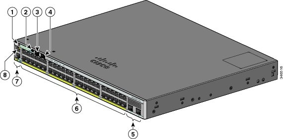
1 Support Cisco FlexStack-Plus technology.2 SFP+ = 10-Gigabit uplink.3 SFP = 1-Gigabit uplink.Front Panel
PoE and PoE+ Ports
The ports provide PoE+ support for devices compliant with IEEE 802.3af, IEEE 802.3at, and ePoE and also provide Cisco prestandard PoE support for Cisco IP Phones and Cisco Aironet Access Points.
The maximum switch power output is either 740 W or 370 W, depending on the switch model. Intelligent power management allows flexible power allocation across all ports.
For switches with a 740 W power budget, you can budget the PoE and PoE+:
For switches with a 370 W power budget, you can budget the PoE and PoE+:
- 15.4 W of PoE output on 24 ports
- 7.7 W of PoE output on 48 ports
- 30 W of PoE+ on 12 ports
- Total power budget can be allocated among the ports
On a per-port basis, you control whether or not a port automatically provides power when an IP phone or an access point is connected.
The PoE ports use RJ-45 connectors with Ethernet pinouts. The maximum cable length is 328 feet (100 meters). The 10BASE-T, 100BASE-TX, 1000BASE-T traffic requires Category 5, Category 5e, or Category 6 unshielded twisted pair (UTP) cable. The 10BASE-T traffic can use Category 3 or Category 4 UTP cable.
Cisco intelligent power management capabilities include enhanced power negotiation, power reservation, and per-port power policing. For information about configuring and monitoring PoE ports, see the switch software configuration guide on Cisco.com.
NoteThe output of the PoE circuit has been evaluated as a Limited Power Source (LPS) per IEC 60950-1.
10/100/1000 Ports
The 10/100/1000 ports use RJ-45 connectors with Ethernet pinouts. The maximum cable length is 328 feet (100 meters). The 100BASE-TX traffic requires Category 5, Category 5e, or Category 6 unshielded twisted pair (UTP) cable. The 10BASE-T traffic can use Category 3 or Category 4 UTP cable.
Related References
Management Ports
The management ports connect the switch to a PC running Microsoft Windows or to a terminal server.
- Ethernet management port
- RJ-45 console port (EIA/TIA-232)
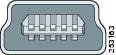
- USB mini-Type B console port (5-pin connector)
The 10/100 Ethernet management port connection uses a standard RJ-45 crossover or straight-through cable. The RJ-45 console port connection uses the supplied RJ-45-to-DB-9 female cable. The USB console port connection uses a USB Type A to 5-pin mini-Type B cable. The USB console interface speeds are the same as the RJ-45 console interface speeds.
If you use the USB mini-Type B console port, the Cisco Windows USB device driver must be installed on any PC connected to the console port (for operation with Microsoft Windows). Mac OS X or Linux do not require special drivers.
The 4-pin mini-Type B connector resembles the 5-pin mini-Type B connectors. They are not compatible. Use only the 5-pin mini-Type B.
With the Cisco Windows USB device driver, you can connect and disconnect the USB cable from the console port without affecting Windows HyperTerminal operations.
The console output always goes to both the RJ-45 and the USB console connectors, but the console input is active on only one of the console connectors at any one time. The USB console takes precedence over the RJ-45 console. When a cable is connected into the USB console port, the RJ-45 console port becomes inactive. Conversely, when the USB cable is disconnected from the USB console port, the RJ-45 port becomes active.
You can use the command-line interface (CLI) to configure an inactivity timeout which reactivates the RJ-45 console if the USB console has been activated and no input activity has occurred on the USB console for a specified time.
After the USB console deactivates due to inactivity, you cannot use the CLI to reactivate it. Disconnect and reconnect the USB cable to reactivate the USB console. For information on using the CLI to configure the USB console interface, see the software guide.
USB Type A Port
The USB Type A port provides access to external USB flash devices (also known as thumb drives or USB keys).
The USB Type A port provides these features:
The port supports Cisco USB flash drives with capacities from 128 MB to 8 GB (USB devices with port densities of 128 MB, 256 MB, 1 GB, 4 GB, 8 GB are supported). When combined with stacking, you can upgrade other switches in the stack from an USB key inserted in any switch within the stack. Cisco IOS software provides standard file system access to the flash device: read, write, erase, and copy, as well as the ability to format the flash device with a FAT file system. It provides you with the ability to automatically upgrade the internal flash with the USB drive’s configuration and image for emergency switch recovery using USB auto-upgrade. This feature checks the internal flash for a bootable image and configuration and if either image or the configuration is not available, then the USB drive is checked for boot images and configuration. If the boot image and configuration are available, these are copied to flash for the reboot.
SFP and SFP+ Module Slots
The switch has either two or four 1-Gigabit SFP or two 10-Gigabit SFP+ module slots. The slots marked SFP+ support both SFP and SFP+ modules. The SFP slots support only the SFP modules.
Table 2 Supported SFP Modules for the Catalyst 2960-X Switches GLC-BX-D=, GLC-BX-U=, GLC-GE-100FX=, GLC-LH-SMD=, GLC-SX-MMD=, GLC-EX-SMD=, GLC-ZX-SMD=, GLC-T=, GLC-LH-SM=, GLC-SX-MM=, GLC-ZX-SM=, CWDM-SFP-1470=, CWDM-SFP-1490=, CWDM-SFP-1510=, CWDM-SFP-1530=, CWDM-SFP-1550=, CWDM-SFP-1570=, CWDM-SFP-1590=, CWDM-SFP-1610=, SFP-10G-LR=, SFP-10G-SR=, SFP-10G-LRM=, SFP-10G-ER=, SFP-10G-LRM-SM=, SFP-H10GB-CU1M=, SFP-H10GB-CU1-5M=, SFP-H10GB-CU2M=, SFP-H10GB-CU2-5M=, SFP-H10GB-CU3M=, SFP-H10GB-CU5M=
GLC-BX-D=, GLC-BX-U=, GLC-GE-100FX=, GLC-LH-SMD=, GLC-SX-MMD=, GLC-EX-SMD=, GLC-ZX-SMD=, GLC-T=, GLC-LH-SM=, GLC-SX-MM=, GLC-ZX-SM=, CWDM-SFP-1470=, CWDM-SFP-1490=, CWDM-SFP-1510=, CWDM-SFP-1530=, CWDM-SFP-1550=, CWDM-SFP-1570=, CWDM-SFP-1590=, CWDM-SFP-1610=.
Catalyst 2960X-24TS-LL
GLC-GE-100FX=, GLC-LH-SM=, GLC-SX-MM=, GLC-LH-SMD=, GLC-SX-MMD=, GLC-EX-SMD=, GLC-T=, GLC-TE=, GLC-EX-SMD=.
For Cisco SFP and SFP+ modules documentation, including compatibility matrixes, refer to this URL: http://www.cisco.com/en/US/products/hw/modules/ps5455/products_device_support_tables_list.html
LEDs
You can use the switch LEDs to monitor switch activity and its performance.
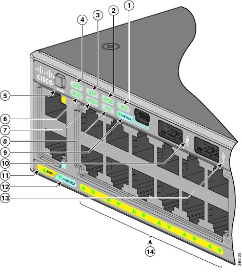
Figure 3. Switch LEDs and Mode Button for the Catalyst 2960-X Switch. This figure shows the switch LEDs and the Mode button that you use to select a port mode.
RPS LED4
USB mini-Type B console port LED
USB Type A port
12
CONSOLE LED
6
Master LED6
13
USB Type A port
7
STACK LED
14
Port LEDs
4 RPS = redundant power system—only on switch models that support RPS.5 Only on switch models that support PoE.6 Only on switch models that support stacking.RPS LED
The RPS LED is only available on switch models that have an RPS port.
Port LEDs and Modes
The port and module slots each has a port LED. As a group or individually, the LEDs show information about the switch and about the ports.
To select or change a mode, press the Mode button until the desired mode is highlighted. When you change port modes, the meanings of the port LED colors also change.
If your switches are stacked and you press the Mode button on any switch, all the switches display the same selected mode. For example, if you press the Mode button on the stack master to display SPEED, all the other stack members display SPEED.
Even if PoE mode is not selected, this LED still shows PoE problems if they are detected.
STACK LED
The STACK LED shows the sequence of member switches in a stack. Up to eight switches can be members of a stack. The first eight port LEDs show the switch member number. For example, if you press the Mode button and select Stack, the port LED 1 blinks green. The LEDs for port 2 and 3 are solid green, as these represent the member numbers of other stack members. The other port LEDs are off because there are no more members in the stack.
Figure 4. STACK LED. This figure shows the LEDs on the first switch, which is stack member number 1.
When you select the STACK LED, the respective STACK LEDs are green when the stack ports (on the switch rear panel) are up, and the respective Stack LEDs are amber when the ports are down. SFP+ module port LEDs 1 and 2 on the switch show the status for stack ports 1 and 2, respectively.
If the port LEDs are green on all the switches in the stack, the stack is operating at full bandwidth. If any port LED is not green, the stack is not operating at full bandwidth.
Console LEDs
The console LEDs show which console port is in use. If you connect a cable to a console port, the switch automatically uses that port for console communication. If you connect two console cables, the USB console port has priority.
Rear Panel
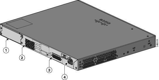
The rear panel of the Catalyst 2960-X switches have a FlexStack-Plus module slot, a fan exhaust, an RPS connector, and an AC power connector.
NoteThe FlexStack-Plus module slot is not available on the Catalyst 2960X-48TS-LL and 2960X-24TS-LL switches.
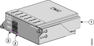
FlexStack-Plus Ports and LEDs
The stacking-capable switch models support stacking with the optional stack kit. It has the FlexStack-Plus module (hot-swappable) that inserts in the slot located in the switch rear panel, and a 0.5-meter FlexStack cable to connect the FlexStack-Plus module ports.
RPS Connector
The Cisco RPS 2300 (model PWR-RPS2300) supports the Catalyst 2960-X switch.
Connect the switch and the redundant power system to different AC power sources.
Cisco RPS 2300
The Cisco RPS 2300 is a redundant power system that can support six external network devices and provide power to one or two failed devices at a time. It senses when the internal power supply of a connected device fails and provides power to the failed device, preventing loss of network traffic. For more information, see the Cisco Redundant Power System 2300 Hardware Installation Guide on Cisco.com at this URL: http://www.cisco.com/en/US/products/ps7148/prod_installation_guides_list.html
The Cisco RPS 2300 has two output levels: –52 V and 12 V with a total maximum output power of 2300 W.
All supported and connected switches can simultaneously communicate with the RPS 2300. You can configure these RPS 2300 features through the switch software:
- Enable RPS active or standby mode for each connected switch
- Configure switch priority for RPS support
- List the connected switches and the power-supply module sizes
- Obtain reports when a switch is powered by the RPS
- Obtain status reports for the RPS power-supply module
- Read and monitor backup, failure, and exception history
Management Options
- Cisco Network Assistant Cisco Network Assistant is a PC-based network management GUI application for LANs of small and medium-sized businesses. You can use the GUI to configure and manage switch clusters or standalone switches. Cisco Network Assistant is available at no cost and can be downloaded from this URL: http://www.cisco.com/en/US/products/ps5931/index.html For information on starting the Network Assistant application, see the Getting Started with Cisco Network Assistant guide on Cisco.com.
- Device Manager You can use Device Manager in the switch memory to manage individual and standalone switches. This web interface provides configuration and monitoring from anywhere in your network. For information, see the switch getting started guide and the Device Manager online help.
- Cisco IOS CLI You can configure and monitor the switch and switch cluster members from the CLI. Access the CLI by connecting your management station to the switch console port or by using Telnet from a remote management station. See the switch command reference on Cisco.com for information.
- Cisco Prime Infrastructure Cisco Prime Infrastructure combines the wireless functionality of Cisco Prime Network Control System (NCS) and the wired functionality of Cisco Prime LAN Management Solution (LMS), with application performance monitoring and troubleshooting capabilities of Cisco Prime Assurance Manager. For more information, see the Cisco Prime Infrastructure documentation on Cisco.com.
- Catalyst Smart Operations The Smart Install feature provides a single point of management (director) in a network. You can use it to provide a zero touch image and configuration upgrade of newly deployed switches and image and configuration downloads for any client switches. For information, see the Cisco Smart Install Configuration Guide on Cisco.com. Auto Smartports macros dynamically configure ports based on the device type detected on the port. When the switch detects a new device, it applies the appropriate Auto Smartports macro on the port. For information about configuring Auto Smartports, see the switch software configuration guide on Cisco.com.
Network Configurations
See the switch software configuration guide on Cisco.com for network configuration concepts and examples of using the switch to create dedicated network segments and interconnecting the segments through Fast Ethernet and Gigabit Ethernet connections.