-
Cisco MDS 9000 Family SAN Volume Controller Configuration Guide
-
New and Changed Information
-
Full Book PDF
-
Preface
-
SVC Product Overview
-
Getting Started
-
Creating and Managing Clusters
-
Managing Back-end Storage
-
Managing Virtual Disks
-
Configuring Hosts
-
Configuring Copy Services
-
Upgrading CSM Software
-
Configuring SPAN on SVC Interfaces
-
Configuring a Dual Fabric SAN Environment
-
 Feedback
Table Of Contents
Configuring iSCSI Hosts in SVC
Configuring Hosts
To continue configuring the using the SVC application for a Cisco MDS 9216 switch or for any switch in the Cisco MDS 9500 Family, you must determine the number of hosts, isolate host traffic to VSAN 1, and map VDisks to hosts.
This chapter includes the following sections:
•
Configuring iSCSI Hosts in SVC
About Hosts
Hosts are identified to the cluster through user configuration. The LUN mapping feature controls which VDisks are accessible by which hosts. A host may contain multiple ports that connect to the SAN. To ease the configuration process, all host ports can be configured in a group. Host ports are referred to by their pWWNs. The specific LUN number is optionally specified when the LUN map is configured. Otherwise, the cluster chooses a LUN number automatically.
Isolating Host Traffic
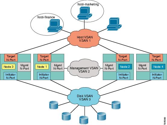
The SVC target N-ports are in VSAN 1 along with the two hosts. To isolate hosts and targets, this example uses the SAN-OS zoning feature.
To isolate hosts using the zoning feature, follow these steps.
Step 1
switch# show fcns database vsan 1VSAN 1:--------------------------------------------------------------------------FCID TYPE PWWN (VENDOR) FC4-TYPE:FEATURE--------------------------------------------------------------------------0x6a0200 N 21:00:00:e0:8b:09:e7:04 (QLogic) scsi-fcp:init0x6a0300 N 21:00:00:e0:8b:09:f0:04 (QLogic) scsi-fcp:init0x6a0003 N 22:20:00:05:30:00:11:69 (Cisco) scsi-fcp:target svc0x6a0006 N 21:23:00:05:30:00:11:69 (Cisco) scsi-fcp:target svc0x6a0009 N 22:23:00:05:30:00:11:69 (Cisco) scsi-fcp:target svc0x6a000c N 21:20:00:05:30:00:11:69 (Cisco) scsi-fcp:target svcTotal number of entries = 6Step 2
switch# config tswitch(config)# zone name host-finance vsan 1switch(config-zone)#Step 3
switch(config-zone)# member pwwn 21:00:00:e0:8b:09:e7:04 --> Host financeswitch(config-zone)# member pwwn 22:20:00:05:30:00:11:69 --> SVC target N-portswitch(config-zone)# member pwwn 21:23:00:05:30:00:11:69 --> SVC target N-portswitch(config-zone)# member pwwn 22:23:00:05:30:00:11:69 --> SVC target N-portswitch(config-zone)# member pwwn 21:20:00:05:30:00:11:69 --> SVC target N-portStep 4
switch(config)# zone name host-marketing vsan 1switch(config-zone)#Step 5
switch(config-zone)# member pwwn 21:00:00:e0:8b:09:f0:04 --> Host marketingswitch(config-zone)# member pwwn 22:20:00:05:30:00:11:69 --> SVC target N-portswitch(config-zone)# member pwwn 21:23:00:05:30:00:11:69 --> SVC target N-portswitch(config-zone)# member pwwn 22:23:00:05:30:00:11:69 --> SVC target N-portswitch(config-zone)# member pwwn 21:20:00:05:30:00:11:69 --> SVC target N-portStep 6
switch(config-zone)# exitswitch(config)# zoneset name main-zset vsan 1switch(config-zoneset)#Step 7
switch(config-zoneset)# member host-financeswitch(config-zoneset)# member host-marketingStep 8
switch(config-zoneset)# exitswitch(config-zone)# exitswitch(config)#Step 9
switch(config)# zoneset activate name main-zset vsan 1Zoneset activation initiated. check zone statusStep 10
switch(config)# exitswitch# show zoneset active vsan 1zoneset name main-zset vsan 1zone name host-finance vsan 1* fcid 0x6a0200 [pwwn 21:00:00:e0:8b:09:e7:04]* fcid 0x6a0003 [pwwn 22:20:00:05:30:00:11:69]* fcid 0x6a0006 [pwwn 21:23:00:05:30:00:11:69]* fcid 0x6a0009 [pwwn 22:23:00:05:30:00:11:69]* fcid 0x6a000c [pwwn 21:20:00:05:30:00:11:69]zone name host-marketing vsan 1* fcid 0x6a0300 [pwwn 21:00:00:e0:8b:09:f0:04]* fcid 0x6a0003 [pwwn 22:20:00:05:30:00:11:69]* fcid 0x6a0006 [pwwn 21:23:00:05:30:00:11:69]* fcid 0x6a0009 [pwwn 22:23:00:05:30:00:11:69]* fcid 0x6a000c [pwwn 21:20:00:05:30:00:11:69]zone name $default_zone$vsan 1You have now created the host VSAN and two zones—host-finance and host-marketing (see Figure 6-1).
Figure 6-1 Identifying the Target N-Ports
Creating Hosts
To create a host, follow these steps.
Step 1
switch# svc-configswitch(svc)# show cluster SampleCluster host candidate-------------------------------------------------------------------------------id pwwn-------------------------------------------------------------------------------1 21:00:00:e0:8b:09:e7:04Use the host candidate's pWWN to identify the host to be mapped.
Step 2
switch(svc)# cluster config SampleClusterswitch(svc-cluster)#Step 3
switch(svc-cluster)# host add Finance1 hostport 21:00:00:e0:8b:09:e7:04Step 4
switch(svc-cluster)# exitswitch(svc)#Step 5
switch(svc)# show cluster SampleCluster host-------------------------------------------name number of ports-------------------------------------------Finance1 1
Mapping VDisks to Hosts
To map VDisks to hosts, follow these steps.
Step 1
switch(svc)# cluster config SampleClusterswitch(svc-cluster)#Step 2
switch(svc-cluster)# host name Finance1switch(svc-cluster-host)#Step 3
switch(svc-cluster-host)# map vdisk crm-data SCSI-lun 10switch(svc-cluster-host)# map vdisk crm-idxswitch(svc-cluster-host)# map vdisk crm-log
Note
Step 4
switch(svc-cluster-host)# exitswitch(svc-cluster)# exitswitch(svc)#Step 5
switch(svc)# show cluster SampleCluster host Finance1host Finance1:Number of port is 1Port WWN is 21:00:00:e0:8b:09:e7:04LUN0: vdik crm-idxLUN1: vdisk crm-logLUN10: vdisk crm-data
Configuring iSCSI Hosts in SVC
This section provides the configuration procedure to allow an iSCSI host to access VDisks exported by an SVC cluster.
Tip
Multipath=no
HostIPsforMP=<ip address of NIC1>,<ip address of NIC2>
ConnFailTimeout=50Refer to the Cisco MDS 9000 Family Configuration Guide for further details on iSCSI concepts and configuration options.
Note
The following example uses the null authentication option. It also displays the configuration for two iSCSI hosts.
To configure two iSCSI hosts to access VDisks exported by an SVC cluster, follow these steps.
Step 1
switch# conf tswitch(config)# iscsi import target fcStep 2
switch(config)# int gigabitethernet 4/1switch(config-if)# ip address 10.11.1.1 255.255.255.0switch(config-if)# no shutswitch(config-if)# exitswitch(config)#Step 3
switch(config)# int iscsi 4/1switch(config-if)# no shutswitch(config-if)# exitswitch(config)#Step 4
The first iSCSI initiator is identified using the IQN name—one nWWN and one pWWNs from the switch's Fibre Channel WWN pool are allocated in the SVC target N-port VSAN (in this example, VSAN 1—See Figure 6-1) keep the mapping permanent:
switch(config)# iscsi initiator name iqn.1987-05.com.cisco:01.e41695d16b1aswitch(config-(iscsi-init))# vsan 1switch(config-(iscsi-init))# static pWWN system-assign 1switch(config-(iscsi-init))# static nWWN system-assignswitch(config-(iscsi-init))# exitswitch(config)#The second iSCSI initiator is identified using the IP address—one pWWN from the switch's Fibre Channel WWN pool is assigned in the SVC target N-port VSAN (in this example, VSAN 1—See Figure 6-1):
switch(config)# iscsi initiator ip address 10.15.1.11switch(config-(iscsi-init))# vsan 1switch(config-(iscsi-init))# static pwwn system-assigned 1switch(config-(iscsi-init))# endswitch#Step 5
switch# show iscsi initiator configurediSCSI Node name is iqn.1987-05.com.cisco:01.e41695d16b1aMember of vsans: 1Node WWN is 20:03:00:0b:fd:44:68:c2No. of PWWN: 1Port WWN is 21:00:00:e1:8b:09:e7:04iSCSI Node name is 10.15.1.11Member of vsans: 1No. of PWWN: 1Port WWN is 20:06:00:0b:fd:44:68:c2Step 6
Zone membership for the iSCSI initiator can either be the iSCSI symbolic node name or the pWWN. In this case, the pWWN can be used since it is statically created.
switch# conf tswitch(config)# zone name host-finance vsan 1switch(config-zone)#Step 7
The following example is based on the symbolic node name.
switch(config-zone)# member symbolic-nodename iqn.1987-05.com.cisco:01.e41695d16b1aThe following example is based on the persistent pWWN assigned to the initiator. You can obtain the pWWN from the output of the show iscsi initiator command.
switch(config-zone)# member pwwn 20:06:00:0b:fd:44:68:c2switch(config-zone)# endswitch#Step 8
switch# svc-configswitch(svc)# show cluster SampleCluster host candidate-------------------------------------------------------------------------------id pwwn-------------------------------------------------------------------------------1 21:00:00:e1:8b:09:e7:042 20:06:00:0b:fd:44:68:c2switch(svc)# cluster config SampleClusterswitch(svc-cluster)# host add iscsi1 hostport 21:00:00:e1:8b:09:e7:04switch(svc-cluster)# host add iscsi2 hostport 20:06:00:0b:fd:44:68:c2Step 9
switch(svc-cluster)# host name iscsi1switch(svc-cluster-host)# map vdisk crm-dataswitch(svc-cluster-host)# exitswitch(svc-cluster)# host name iscsi2switch(svc-cluster-host)# map vdisk crm-dataswitch(svc-cluster-host)# endswitch#Step 10