-
Cisco MDS 9000 Family Configuration Guide, Release 1.0(2)
-
Index
-
Preface
-
Product Overview
-
Before You Begin
-
Initial Configuration
-
Configuring High Availability
-
Software Images
-
Managing Modules
-
Managing System Hardware
-
Configuring and Managing VSANs
-
Configuring Interfaces
-
Configuring Trunking
-
Configuring PortChannels
-
Configuring and Managing Zones
-
Managing FLOGI, Name Server, and RSCN Databases
-
Configuring System Security and AAA Services
-
Configuring Fibre Channel Routing Services and Protocols
-
Configuring IP Services
-
Configuring Call Home
-
Configuring Domain Parameters
-
Configuring Traffic Management
-
Configuring System Message Logging
-
Discovering SCSI Targets
-
Monitoring Network Traffic Using SPAN
-
Advanced Features and Concepts
-
Configuring Fabric Configuration Servers
-
Monitoring System Processes and Logs
-
 Feedback
Table Of Contents
Configuring Fibre Channel Interfaces
Configuring a Range of Interfaces
Configuring Administrative Speeds
Configuring Interface Descriptions
Configuring Buffer-to-Buffer Credits
Configuring Receive Data Field Size
Configuring Switchport Defaults
Configuring the Management Interface
Displaying Interface Information
Displaying TL Port Information
Configuring Interfaces
A switch's main function is to relay frames from one data link to another. To do that, the characteristics of the interfaces through which the frames are received and sent must be defined. The configured interfaces can be Fibre Channel interfaces, management interface (mgmt0), or VSAN interfaces.
This chapter describes the basic interface configuration to get your switch up and running. It includes the following sections:
•
Configuring Fibre Channel Interfaces
•
•
Note
Before you begin configuring the switch, you need to ensure that the modules in the chassis are functioning as designed. To verify the status of a module at any time, issue the show module command in EXEC mode (see the "Verifying the Module Status" section).
Configuring Fibre Channel Interfaces
This section describes Fibre Channel interface characteristics, including (but are not limited to) modes, states, and speeds. It includes the following sections:
•
•
•
•
About Interface Modes
Each physical Fibre Channel interface in a switch may operate in one of several modes: E port, F port, FL port, TL port, TE port, and SD port (see Figure 9-1). Besides these modes, each interface may be configured in auto or Fx port mode. These two modes determine the port type during interface initialization. A brief description of each interface mode follows.
Figure 9-1 Cisco MDS 9000 Family Switch Interface Modes
Note
Each interface has an associated administrative configuration and an operational status:
•
•
E Port
In expansion port (E port) mode, an interface functions as a fabric expansion port. This port may be connected to another E port to create an Inter-Switch Link (ISL) between two switches. E ports carry frames between switches for configuration and fabric management. They serve as a conduit between switches for frames destined to remote N ports and NL ports. E ports support class 2, class 3, and class F service.
An E port connected to another switch may also be configured to form a PortChannel (see "Configuring PortChannels").
F Port
In fabric port (F port) mode, an interface functions as a fabric port. This port may be connected to a peripheral device (host or disk) operating as an N port. An F port can be attached to only one N port. F ports support class 2 and class 3 service.
FL Port
In fabric loop port (FL port) mode, an interface functions as a fabric loop port. This port may be connected to one or more NL ports (including FL ports in other switches) to form a public arbitrated loop. If more than one FL port is detected on the arbitrated loop during initialization, only one FL port becomes operational and the other FL ports enter nonparticipating mode. FL ports support class 2 and class 3 service.
TL Port
In translative loop port (TL port) mode, an interface functions as a translative loop port. It may be connected to one or more private loop devices (NL ports). TL port mode is specific to Cisco MDS 9000 family switches and have similar properties as FL ports. TL ports enable communication between a private loop device and one of the following devices:
•
•
•
•
See the "Displaying TL Port Information" section. TL ports support class 2 and class 3 services.
Note
TE Port
In trunking E port (TE port) mode, an interface functions as a trunking expansion port. It may be connected to another TE port to create an Extended ISL (EISL) between two switches. TE ports are specific to Cisco MDS 9000 family switches. They expand the functionality of E ports to support the following:
•
•
•
In TE-port mode, all frames are transmitted in EISL frame format, which contains VSAN information. Interconnected switches use the VSAN ID to multiplex traffic from one or more VSANs across the same physical link. This feature is referred to as trunking in the Cisco MDS 9000 Family (see "Configuring Trunking"). TE ports support class 2, class 3, and class F service.
SD Port
In SPAN destination port (SD port) mode, an interface functions as a switched port analyzer (SPAN). The SPAN feature is specific to switches in the Cisco MDS 9000 Family. It monitors network traffic that passes though a Fibre Channel interface. This monitoring is done using a standard Fibre Channel analyzer (or a similar switch probe) that is attached to an SD port. SD ports do not receive frames, they merely transmit a copy of the source traffic. The SPAN feature is nonintrusive and does not affect switching of network traffic for any SPAN source ports (see "Monitoring Network Traffic Using SPAN").
Fx Port
Interfaces configured as Fx ports are allowed to operate in either F port or FL port mode. The Fx port mode is determined during interface initialization depending on the attached N port or NL port. This administrative configuration disallows interfaces to operate in any other mode—for example, preventing an interface to connect to another switch.
Auto Mode
Interfaces configured as auto are allowed to operate in one of the following modes: F port, FL port, E port, or TE port. The port mode is determined during interface initialization. For example, if the interface is connected to a node (host or disk), it operates in F port or FL port mode depending on the N port or NL port mode. If the interface is attached to a third-party switch, it operates in E port mode. If the interface is attached to another switch in the Cisco MDS 9000 Family, it may become operational in TE port mode (see "Configuring Trunking"). TL ports and SD ports are not determined during initialization and are administratively configured.
About Interface States
The interface state depends on the administrative configuration of the interface and the dynamic state of the physical link.
Administrative States
The administrative state refers to the administrative configuration of the interface as described in Table 9-1.
Operational States
The operational state indicates the current operational state of the interface as described in Table 9-2.
Reason Codes
Reason codes are dependent on the operational state of the interface as described in Table 9-3.
Table 9-3 Reason Codes for Interface States
Up
Up
None.
Down
Down
Administratively down—If you administratively configure an interface as down, you disable the interface. No traffic is received or transmitted.
Up
Down
See Table 9-4.
If the administrative state is up and the operational state is down, the reason code differs based on the nonoperational reason code as described in Table 9-4.
Configuring 32-port Switching Modules
The 32-port 1/2-Gbps switching module contains 8 port groups of 4 ports each. When configuring these modules the following guidelines apply:
•
•
•
•
Configuring FC Interfaces
To configure a Fibre Channel interface, follow these steps:
Step 1
Enters configuration mode.
Step 2
Configures the specified interface.
When a Fibre Channel interface is configured, it is automatically assigned a unique world wide name (WWN). If the interface's operational state is up, it is also assigned a Fibre Channel ID (FC ID).
Configuring a Range of Interfaces
To configure a range of interfaces, follow these steps:
Disabling Interfaces
Interfaces on a port are shut down by default (unless you modified the initial configuration). To enable traffic flow, follow these steps:
Configuring Interface Modes
To configure the interface mode, follow these steps:
Configuring Administrative Speeds
By default, the administrative speed for an interface is automatically calculated by the switch. To configure the administrative speed of the interface, follow these steps:
Configuring Interface Descriptions
To configure a description for an interface, follow these steps:
Configuring Buffer-to-Buffer Credits
Buffer-to-buffer credits (BB_credits) are a flow control mechanism to ensure that FC switches do not run out of buffers, since switches must not drop frames. Buffer Credits are negotiated on a per-hop basis.
The receive BB_credit value may be configured for each FC interface. In most cases, you don't need to modify the default configuration.
Note
To configure buffer-to-buffer credits to a Fibre Channel interface, follow these steps:
Configuring Receive Data Field Size
You can also configure the receive data field size for Fibre Channel interfaces by issuing the switchport fcrxbufsize command. The default data field size is 2112 bytes, the frame length will be 2148 bytes.
To configure data field size for a Fibre Channel interface, follow these steps:
Configuring the Beacon Mode
By default, the beacon mode is disabled on all switches. The beacon mode is indicated by a flashing green light that helps you identify the physical location of the specified interface. The beacon command has no effect on the operation of the interface.
To disable beacon mode for a specified interface or range of interfaces, follow these steps:
Identifying the Beacon LEDs
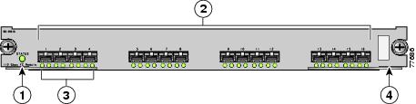
Figure 9-2 displays the status, link, and speed LEDs in a 16-port switching module.
Figure 9-2 Cisco MDS 9000 Family Switch Interface Modes
Status LED (see the "Identifying Module LEDs" section)
Link LEDs (see the "Identifying Module LEDs" section) and speed LEDs (explained in this section).
1/2-Gbps Fibre Channel port group (see the "Configuring 32-port Switching Modules" section)
Asset tag (See the Cisco MDS 9000 Family Hardware Installation Guide).
Each port has one link LED on the left and one speed LED on the right.
The speed LED displays the speed of the port interface:
•
•
The speed LED also displays if the beacon mode is enabled or disabled:
•
•
Configuring Switchport Defaults
You can configure default values for various switchport attributes. If you configure the following attributes, they will be applied globally to all future switchport configurations, even if you do not individually specify them at that time.
To configure switchport attributes, follow these steps:
Default Settings
Table 9-5 lists the default settings for Fibre Channel interface parameters.
Configuring the Management Interface
You can remotely configure the switch through the management interface (mgmt0). To configure a connection remotely, you must configure the IP parameters (IP address, subnet mask, and default gateway) from the CLI so that the switch is reachable.
Note
To configure the mgmt0 Ethernet interface, follow these steps:
The management port (mgmt0) is autosensing and operates as full duplex mode and 100 Mbps speed. The speed and mode cannot be configured.
Note
Configuring VSAN Interfaces
VSANs apply to Fibre Channel fabrics and enable you to configure multiple isolated SAN topologies within the same physical infrastructure. You can create an IP interface on top of a VSAN. You can then use this interface to send frames to this VSAN. To use this feature, you must configure the IP address for this VSAN. VSAN interfaces cannot be created for nonexisting VSANs.
Follow these guidelines when creating or deleting VSAN interfaces:
•
•
•
To create a VSAN interface, follow these steps:
Step 1
Enters configuration mode.
Step 2
switch(config)# interface vsan 5switch(config-if)#Configures a VSAN with the ID 5.
You can configure each interface only in one VSAN.
After configuring the VSAN interface, you can configure an IP address or Virtual Router Redundancy Protocol (VRRP) features (see "Configuring IP Services").
Displaying Interface Information
The show interface command is invoked from the EXEC mode and displays the interface configurations. Without any arguments, this command displays the information for all the configured interfaces in the switch. See Examples 9-1 to 9-9.
Example 9-1 Displays All Interfaces
switch# show interfacefc3/1 is trunkingHardware is Fibre ChannelPort WWN is 20:81:00:05:30:00:12:5ePeer port WWN is 22:01:00:05:30:00:12:9eAdmin port mode is E, trunk mode is autoPort mode is TEPort vsan is 2Speed is 2 GbpsReceive B2B Credit is 255Receive Buffer Size is 2112Beacon is turned offTrunk vsans (admin allowed and active) (1-15)Trunk vsans (up) (1-15)Trunk vsans (isolated) ()Trunk vsans (initializing) ()5 minutes input rate 40 bits/sec, 5 bytes/sec, 0 frames/sec5 minutes output rate 24 bits/sec, 3 bytes/sec, 0 frames/sec2161 frames input, 182556 bytes, 0 discards0 CRC, 0 unknown class0 too long, 0 too short2164 frames output, 139904 bytes, 0 discards1 input OLS, 1 LRR, 1 NOS, 0 loop inits2 output OLS, 1 LRR, 1 NOS, 0 loop inits...fc9/9 is upHardware is Fibre ChannelPort WWN is 22:09:00:05:30:00:12:5eAdmin port mode is auto, trunk mode is autoPort mode is FL, FCID is 0xef0100Port vsan is 1Speed is 1 GbpsReceive B2B Credit is 16Receive Buffer Size is 2112Beacon is turned off5 minutes input rate 0 bits/sec, 0 bytes/sec, 0 frames/sec5 minutes output rate 0 bits/sec, 0 bytes/sec, 0 frames/sec5 frames input, 560 bytes, 0 discards0 CRC, 0 unknown class0 too long, 0 too short4 frames output, 524 bytes, 0 discards0 input OLS, 0 LRR, 0 NOS, 2 loop inits2 output OLS, 0 LRR, 1 NOS, 1 loop inits...sup-fc0 is upHardware is Fibre ChannelSpeed is 1 Gbps74994 packets input, 8076884 bytes0 multicast frames, 0 compressed0 input errors, 0 frame, 0 overrun 0 fifo74991 packets output, 7689168 bytes, 0 underruns0 output errors, 0 collisions, 0 fifo0 carrier errorsmgmt0 is upHardware is FastEthernetAddress is 0005.3000.2c5aInternet address is 172.22.90.38/24MTU 1500 bytes, Speed is 100 Mbps9319 packets input, 738784 bytes0 multicast frames, 0 compressed0 input errors, 0 frame, 0 overrun 0 fifo150 packets output, 34090 bytes, 0 underruns0 output errors, 0 collisions, 0 fifo0 carrier errorsvsan1 is up, line protocol is upWWPN is 10:00:00:05:30:00:12:63, FCID is 0xef001eInternet address is 10.10.11.10/24MTU 1500 bytes, BW 1000000 Kbit0 packets input, 0 bytes, 0 errors, 0 multicast0 packets output, 0 bytes, 0 errors, 0 dropped...port-channel 2 is trunkingHardware is Fibre ChannelPort WWN is 24:02:00:05:30:00:26:1eAdmin port mode is E, trunk mode is onPort mode is TEPort vsan is 1Speed is 4 GbpsTrunk vsans (admin allowed and active) (1-5)Trunk vsans (up) (1-5)Trunk vsans (isolated) ()Trunk vsans (initializing) ()5 minutes input rate 8 bits/sec, 1 bytes/sec, 0 frames/sec5 minutes output rate 8 bits/sec, 1 bytes/sec, 0 frames/sec3534 frames input, 251672 bytes, 0 discards0 CRC, 0 unknown class0 too long, 0 too short3534 frames output, 176108 bytes, 0 discards9 input OLS, 8 LRR, 0 NOS, 0 loop inits13 output OLS, 11 LRR, 11 NOS, 0 loop inits...You can also specify arguments to display interface information.
Example 9-2 Displays a Range of Interfaces
switch# show interface fc2/5 - 6 , fc2/9switch# show int fc2/5 - 10fc2/5 is trunkingHardware is Fibre ChannelPort WWN is 20:45:00:05:30:00:26:1ePeer port WWN is 21:85:00:05:30:00:25:9eAdmin port mode is E, trunk mode is onPort mode is TEPort vsan is 1Speed is 2 GbpsReceive B2B Credit is 255Receive Buffer Size is 2112Encapsulation is normalBeacon is turned offBelongs to port-channel 2Trunk vsans (admin allowed and active) (1-5)Trunk vsans (up) (1-5)Trunk vsans (isolated) ()Trunk vsans (initializing) ()5 minutes input rate 8 bits/sec, 1 bytes/sec, 0 frames/sec5 minutes output rate 8 bits/sec, 1 bytes/sec, 0 frames/sec1542 frames input, 105748 bytes, 0 discards0 CRC, 0 unknown class0 too long, 0 too short1542 frames output, 76656 bytes, 0 discards5 input OLS, 5 LRR, 0 NOS, 0 loop inits8 output OLS, 6 LRR, 6 NOS, 0 loop initsfc2/9 is upHardware is Fibre ChannelPort WWN is 20:49:00:05:30:00:26:1ePeer port WWN is 21:89:00:05:30:00:25:9eAdmin port mode is E, trunk mode is offPort mode is E, FCID is 0x7c0000Port vsan is 3Speed is 2 GbpsReceive B2B Credit is 255Receive Buffer Size is 2112Encapsulation is normalBeacon is turned off5 minutes input rate 0 bits/sec, 0 bytes/sec, 0 frames/sec5 minutes output rate 0 bits/sec, 0 bytes/sec, 0 frames/sec624 frames input, 37736 bytes, 0 discards0 CRC, 0 unknown class0 too long, 0 too short625 frames output, 30248 bytes, 0 discards3 input OLS, 3 LRR, 2 NOS, 0 loop inits7 output OLS, 5 LRR, 5 NOS, 0 loop initsExample 9-3 Displays a Specific Interface
switch# show interface fc2/9fc2/9 is upHardware is Fibre ChannelPort WWN is 20:49:00:05:30:00:26:1ePeer port WWN is 21:89:00:05:30:00:25:9eAdmin port mode is E, trunk mode is offPort mode is E, FCID is 0x7c0000Port vsan is 3Speed is 2 GbpsReceive B2B Credit is 255Receive Buffer Size is 2112Encapsulation is normalBeacon is turned off5 minutes input rate 0 bits/sec, 0 bytes/sec, 0 frames/sec5 minutes output rate 0 bits/sec, 0 bytes/sec, 0 frames/sec624 frames input, 37736 bytes, 0 discards0 CRC, 0 unknown class0 too long, 0 too short625 frames output, 30248 bytes, 0 discards3 input OLS, 3 LRR, 2 NOS, 0 loop inits7 output OLS, 5 LRR, 5 NOS, 0 loop initsExample 9-4 Displays a VSAN Interface
switch# show int vsan 2vsan2 is up, line protocol is upWWPN is 10:00:00:05:30:00:59:1f, FCID is 0xb90100Internet address is 10.1.1.1/24MTU 1500 bytes, BW 1000000 Kbit0 packets input, 0 bytes, 0 errors, 0 multicast0 packets output, 0 bytes, 0 errors, 0 droppedExample 9-5 Displays Port Description
switch# show interface description-------------------------------------------------------------------------------Interface Description-------------------------------------------------------------------------------fc3/1 test intestfc3/2 --fc3/3 --fc3/4 TE portfc3/5 --fc3/6 --fc3/10 Next hop switch 5fc3/11 --fc3/12 --fc3/16 ---------------------------------------------------------------------------------Interface Description-------------------------------------------------------------------------------port-channel 1 --port-channel 5 --port-channel 6 --Example 9-6 Displays Interface Information in a Brief Format
switch# show interface brief-------------------------------------------------------------------------------Interface Vsan Admin Admin Status Oper Oper Port-channelMode Trunk Mode SpeedMode (Gbps)-------------------------------------------------------------------------------fc2/5 1 E on trunking TE 2 port-channel 2 fc2/6 1 E on trunking TE 2 port-channel 2 fc2/7 1 E on down -- -- -- fc2/8 1 auto on fcotAbsent -- -- -- fc2/9 3 E off up E 2 -- fc2/12 3 E on down -- -- port-channel 4 fc3/14 1 SD -- up SD 1 -- fc9/1 1 auto on fcotAbsent -- -- -- fc9/9 1 auto auto up FL 1 -- -------------------------------------------------------------------------------Interface Status Speed-------------------------------------------------------------------------------sup-fc0 up 1-------------------------------------------------------------------------------Interface Status IP Address Speed MTU-------------------------------------------------------------------------------mgmt0 up 172.22.90.38/24 100 Mbps 1500-------------------------------------------------------------------------------Interface Status IP Address Speed MTU-------------------------------------------------------------------------------vsan1 up 10.10.11.10/24 1 Gbps 1500vsan2 up 10.10.12.10/24 1 Gbps 1500-------------------------------------------------------------------------------Interface Vsan Admin Status Oper OperTrunk Mode SpeedMode (Gbps)-------------------------------------------------------------------------------port-channel 1 1 off noOperMembers -- --port-channel 2 1 on trunking TE 4port-channel 3 3 off noOperMembers -- --Example 9-7 Displays Interface Counters
switch# show interface countersfc3/15 minutes input rate 24 bits/sec, 3 bytes/sec, 0 frames/sec5 minutes output rate 16 bits/sec, 2 bytes/sec, 0 frames/sec3502 frames input, 268400 bytes0 discards, 0 CRC, 0 unknown class0 too long, 0 too short3505 frames output, 198888 bytes0 discards1 input OLS, 1 LRR, 1 NOS, 0 loop inits2 output OLS, 1 LRR, 1 NOS, 0 loop inits1 link failures, 1 sync losses, 1 signal losses...fc9/85 minutes input rate 0 bits/sec, 0 bytes/sec, 0 frames/sec5 minutes output rate 0 bits/sec, 0 bytes/sec, 0 frames/sec0 frames input, 0 bytes0 class-2 frames, 0 bytes0 class-3 frames, 0 bytes0 class-f frames, 0 bytes0 discards, 0 CRC, 0 unknown class0 too long, 0 too short0 frames output, 0 bytes0 class-2 frames, 0 bytes0 class-3 frames, 0 bytes0 class-f frames, 0 bytes0 discards0 input OLS, 0 LRR, 0 NOS, 0 loop inits0 output OLS, 0 LRR, 0 NOS, 0 loop inits0 link failures, 0 sync losses, 0 signal losses...sup-fc0114000 packets input, 11585632 bytes0 multicast frames, 0 compressed0 input errors, 0 frame, 0 overrun 0 fifo113997 packets output, 10969672 bytes, 0 underruns0 output errors, 0 collisions, 0 fifo0 carrier errorsmgmt031557 packets input, 2230860 bytes0 multicast frames, 0 compressed0 input errors, 0 frame, 0 overrun 0 fifo26618 packets output, 16824342 bytes, 0 underruns0 output errors, 0 collisions, 7 fifo0 carrier errorsvsan10 packets input, 0 bytes, 0 errors, 0 multicast0 packets output, 0 bytes, 0 errors, 0 dropped...port-channel 15 minutes input rate 0 bits/sec, 0 bytes/sec, 0 frames/sec5 minutes output rate 0 bits/sec, 0 bytes/sec, 0 frames/sec0 frames input, 0 bytes0 class-2 frames, 0 bytes0 class-3 frames, 0 bytes0 class-f frames, 0 bytes0 discards, 0 CRC, 0 unknown class0 too long, 0 too short0 frames output, 0 bytes0 class-2 frames, 0 bytes0 class-3 frames, 0 bytes0 class-f frames, 0 bytes0 discards0 input OLS, 0 LRR, 0 NOS, 0 loop inits0 output OLS, 0 LRR, 0 NOS, 0 loop inits0 link failures, 0 sync losses, 0 signal losses
Note
Example 9-8 Displays Interface Counters in Brief Format
switch# show interface counters brief-------------------------------------------------------------------------------Interface Input (rate is 5 min avg) Output (rate is 5 min avg)----------------------------- -----------------------------Rate Total Rate TotalMbits/s Frames Mbits/s Frames-------------------------------------------------------------------------------fc3/1 0 3871 0 3874fc3/2 0 3902 0 4232fc3/3 0 3901 0 4138fc3/4 0 3895 0 3894fc3/5 0 3890 0 3897fc9/8 0 0 0 0fc9/9 0 5 0 4fc9/10 0 4186 0 4182fc9/11 0 4331 0 4315-------------------------------------------------------------------------------Interface Input (rate is 5 min avg) Output (rate is 5 min avg)----------------------------- -----------------------------Rate Total Rate TotalMbits/s Frames Mbits/s Frames-------------------------------------------------------------------------------port-channel 1 0 0 0 0port-channel 2 0 3946 0 3946Example 9-9 Displays Transceiver Information
switch# show interface transceiver...fc9/6 fcot is presentname is CISCO-AGILENTpart number is QFBR-5796Lrevision isserial number is A00156980basic id fields (bytes 0-63)0x03 0x04 0x07 0x00 0x00 0x00 0x00 0x200x40 0x0C 0x05 0x01 0x15 0x00 0x00 0x000x1E 0x0F 0x00 0x00 0x43 0x49 0x53 0x430x4F 0x2D 0x41 0x47 0x49 0x4C 0x45 0x4E0x54 0x20 0x20 0x20 0x00 0x00 0x30 0xD30x51 0x46 0x42 0x52 0x2D 0x35 0x37 0x390x36 0x4C 0x20 0x20 0x20 0x20 0x20 0x200x20 0x20 0x20 0x20 0x00 0x00 0x00 0x86extended id fields (bytes 64-95)0x00 0x1A 0x00 0x00 0x41 0x30 0x30 0x310x35 0x36 0x39 0x38 0x30 0x20 0x20 0x200x20 0x20 0x20 0x20 0x30 0x32 0x30 0x380x32 0x30 0x20 0x20 0x00 0x00 0x00 0x44vendor specific data (bytes 96-127)0x00 0x00 0x06 0x36 0x31 0x8D 0x23 0xB50x8E 0xC2 0x13 0x9E 0xAC 0x57 0x47 0xB80xAB 0x37 0x19 0x00 0x00 0x00 0x00 0x000x00 0x00 0x00 0x00 0x01 0x7D 0x67 0x74fc9/7 fcot is present but not supportedname is IBMpart number is IBM42P21SNYrevision is AA20serial number is 53P1487000WDNbasic id fields (bytes 0-63)0x03 0x00 0x07 0x00 0x00 0x00 0x00 0x200x40 0x0C 0x05 0x01 0x15 0x00 0x00 0x000x1E 0x0F 0x00 0x00 0x49 0x42 0x4D 0x200x20 0x20 0x20 0x20 0x20 0x20 0x20 0x200x20 0x20 0x20 0x20 0x00 0x08 0x00 0x5A0x49 0x42 0x4D 0x34 0x32 0x50 0x32 0x310x53 0x4E 0x59 0x20 0x20 0x20 0x20 0x200x41 0x41 0x32 0x30 0x00 0x00 0x00 0x07extended id fields (bytes 64-95)0x00 0x1A 0x05 0x05 0x35 0x33 0x50 0x310x34 0x38 0x37 0x30 0x30 0x30 0x57 0x440x4E 0x20 0x20 0x20 0x30 0x32 0x30 0x350x31 0x30 0x30 0x31 0x00 0x00 0x00 0x12vendor specific data (bytes 96-127)0x49 0x42 0x4D 0x20 0x53 0x46 0x50 0x530x20 0x41 0x52 0x45 0x20 0x43 0x4C 0x410x53 0x53 0x20 0x31 0x20 0x4C 0x41 0x530x45 0x52 0x20 0x53 0x41 0x46 0x45 0x20...Displaying TL Port Information
Private loop devices refer to legacy devices that reside on arbitrated loops. These devices are not aware of a switch fabric since they only communicate with devices on the same physical loop.
The legacy devices are used in Fibre Channel networks and devices outside the loop may need to communicate with them.The communication functionality is provided through TL ports.
Use the switchport mode command to configure a TL port (see the "Configuring Interface Modes" section).
The show tlport command displays the TL port interface configurations. This command provides a list of all TL ports configured on a box and shows the associated VSAN, the FC ID for the port (only domain and area are valid), and the current operational state of the TL port (up or initializing). See Examples 9-10 to 9-9.
Example 9-10 Displays the TL Ports in All VSANs
switch# show tlport list-------------------------------Interface Vsan FC-ID State------------------------- ------fc1/16 1 0x420000 Initfc2/26 1 0x150000 UpTL ports allow a private device (devices that physically reside on the loop) to see a fabric device and vice-versa by proxying fabric devices on the loop. Fabric devices are proxied by allocating each fabric device an ALPA on this loop.
In addition to these proxied devices, other virtual devices (local or remote domain controller addresses) are also allocated ALPAs on the loop. A switch reserves the ALPA for its own communication with private devices, and the switch acts as a SCSI Initiator.
The first column in the output of the show tlport interface command is the ALPA identity of the device on the loop. The second lists the port WWNs, the third lists the node WWNs for each device, the fourth identifies the device as a SCSI initiator or target, and the last column is the real FC ID of the device.
Example 9-11 Displays the Detailed Information for a Specific TL Port
switch# show tlport interface fc1/16 allfc1/16 is up, vsan 1, FCID 0x420000-------------------------------------------------------------------------------- alpa pWWN nWWN SCSI Type Device FC-ID -------------------------------------------------------------------------------- 0x01 20:10:00:05:30:00:4a:de 20:00:00:05:30:00:4a:de Initiator Proxied 0xfffc42 0x73 22:00:00:20:37:39:ae:54 20:00:00:20:37:39:ae:54 Target Private 0x420073 0xef 20:10:00:05:30:00:4a:de 20:00:00:05:30:00:4a:de Initiator Switch 0x0000efExample 9-12 Displays TL Port Information for Private Devices
switch# show tlport int fc1/16 prifc1/16 is up, vsan 1, FCID 0x420000------------------------------------------------------------------------alpa pWWN nWWN SCSI Type FC-ID ------------------------------------------------------------------------0x73 22:00:00:20:37:39:ae:54 20:00:00:20:37:39:ae:54 Target 0x4200730x74 22:00:00:20:37:38:d3:de 20:00:00:20:37:38:d3:de Target 0x420074Example 9-13 Displays TL Port Information for Proxied Devices
switch# show tlport int fc1/16 proxfc1/16 is up, vsan 1, FCID 0x420000------------------------------------------------------------------------alpa pWWN nWWN SCSI Type FC-ID ------------------------------------------------------------------------0x01 20:10:00:05:30:00:4a:de 20:00:00:05:30:00:4a:de Initiator 0xfffc420x02 21:00:00:e0:8b:01:95:e7 20:00:00:e0:8b:01:95:e7 Initiator 0x420100