Feedback Feedback
|
Table Of Contents
Cisco MDS 9124 and Cisco MDS 9134 Multilayer Fabric Switch Quick Start Guide
Obtaining Technical Assistance
Cisco Technical Support & Documentation Website
Cisco MDS 9124 and Cisco MDS 9134 Multilayer Fabric Switch Quick Start Guide
Date: April 2009
Text Part Number: OL-19586-011 Overview
Cisco MDS 9124 Switch
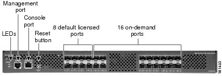
The Cisco MDS 9124 Multilayer Fabric Switch has 24 Fibre Channel ports with speeds of 4, 2, and 1 Gbps. The Cisco MDS 9124 Switch is based on System-on-a-Chip (SOC), a new technology from Cisco, and it has these features:
•
8 default licensed ports
•
•
•
•
•
The front of the Cisco MDS 9124 Switch contains the LEDs, the console and management ports, the reset button, the 8 default licensed ports, and the 16 on-demand ports. See Figure 1.
Figure 1 Front View of the Cisco MDS 9124 Switch
The rear of the Cisco MDS 9124 Switch contains the redundant power supplies, the AC power receptacle, and the fans.
See Figure 2.Figure 2 Rear View of the Cisco MDS 9124 Switch
Note
Cisco MDS 9134 Switch
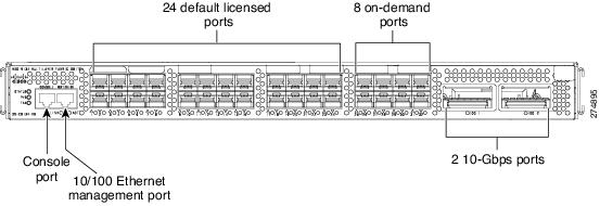
The Cisco MDS 9134 Multilayer Fabric Switch has 32 Fibre Channel ports with speeds of 4, 2, and 1 Gbps. The Cisco MDS 9134 switch has these features:
•
•
•
•
•
•
The front of the Cisco MDS 9134 Switch contains the LEDs, the console and management ports, the reset button, the 24 default licensed ports, and the 8 on-demand ports. See Figure 3.
Figure 3
Front View of the Cisco MDS 9134 Switch
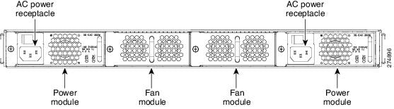
The rear of the Cisco MDS 9134 Switch contains the fan modules and the power modules. See Figure 4.
Figure 4 Rear View of the Cisco MDS 9134 Switch
2 Verify Your Shipping Contents
Verify that you have received all items, including the following:
•
•
•
•
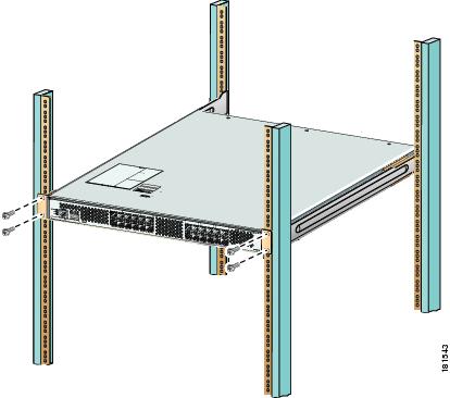
3 Install the Switch
Install the switch in one of the following enclosures:
•
•
•
See Figure 5 for an example of a rack mount.
Figure 5 Example Rack Mount
Note
4 Install the SFPs
Install one of the following SFPs in each empty port:
•
•
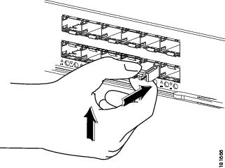
See Figure 6 for SFP installation.
Figure 6 SFP Installation
5 Power Up the Switch
To power up the switch, follow these steps:
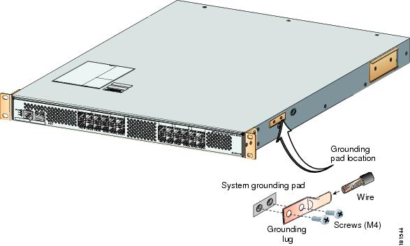
Step 1
Figure 7 Switch Ground
Step 2
The Cisco MDS 9124 and the Cisco MDS 9134 switches support dual AC and DC power supplies. Each power supply provides sufficient power to maintain switch operation in the event of a single power supply failure. Power supplies are hot swappable and can be individually replaced without disruption to the system. The power supply has two LEDs, AC ok and DC ok. Power supply status is also indicated on a front panel LED.
The Cisco MDS 9124 Switch includes a front panel reset button that resets the switch without cycling the power.
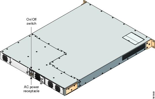
The Cisco MDS 9134 Switch includes a reset button on the left side of the switch.Step 3
Figure 8 Power Receptacle and On/Off Switch on Cisco MDS 9124 Switch
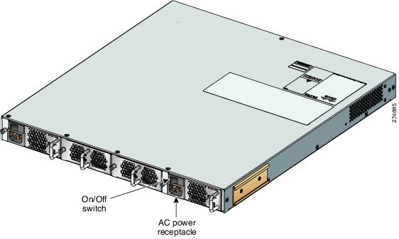
Figure 9
Power Receptacle and On/Off Switch on Cisco MDS 9134 Switch
6 Set Up a Network
To set up a network, follow these steps:
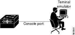
Step 1
Step 2
Figure 10 Connection to Terminal Emulator.
Note
Step 3
Step 4
a.
Caution
b.
Example 1 IP Address Step in the Setup Utility
Continue with Out-of-band (mgmt0) management configuration? {yes/no]: yesMgmt0 IPV4 address: 209.165.200.225Mgmt0 IPV4 netmask: 255.255.255.224c.
Note
7 Connect Devices
To connect devices, follow these steps:
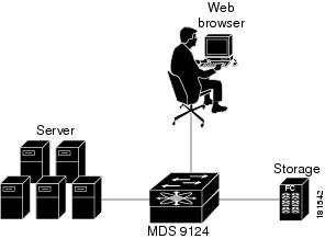
Step 1
Step 2
Figure 11 Server and Storage Connection
Note
8 Install Device Manager
To install Device Manager, follow these steps:
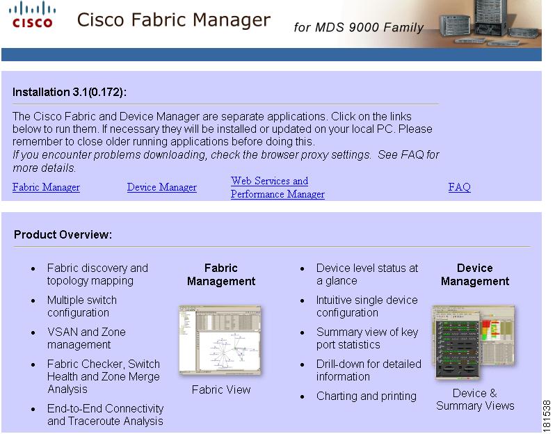
Step 1
Step 2
Figure 12 Device Manager Installation
Step 3
9 Use the Quick Config Wizard
To enable ports and assign zone memberships, follow these steps:
Step 1
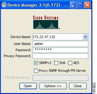
Step 2
Step 3
Figure 13 Device Manager Login
Step 4
Step 5
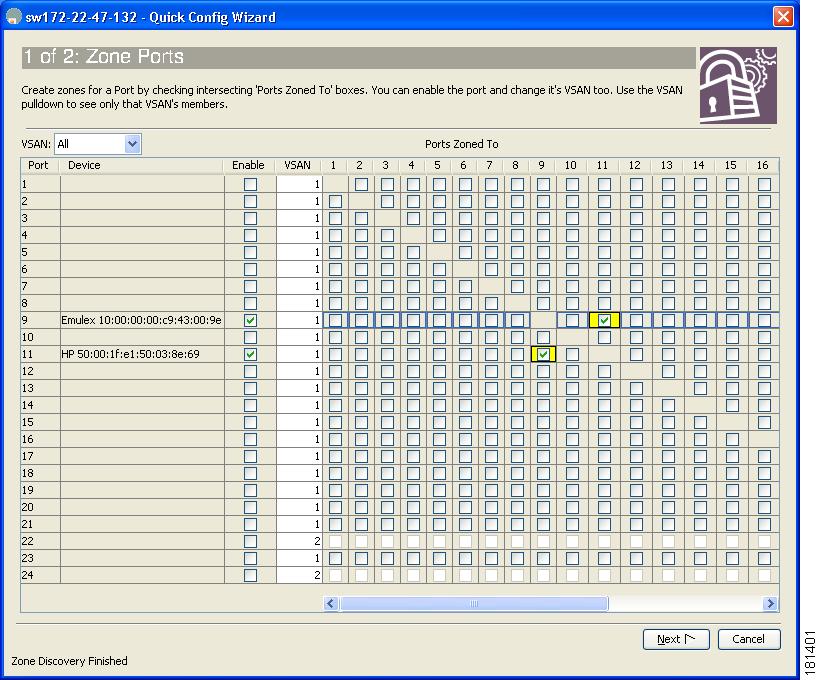
Figure 14 Enable Zone Ports
Step 6
When you check this check box, the second enabled port automatically becomes checked. Both ports are now members of the same zone.Step 7
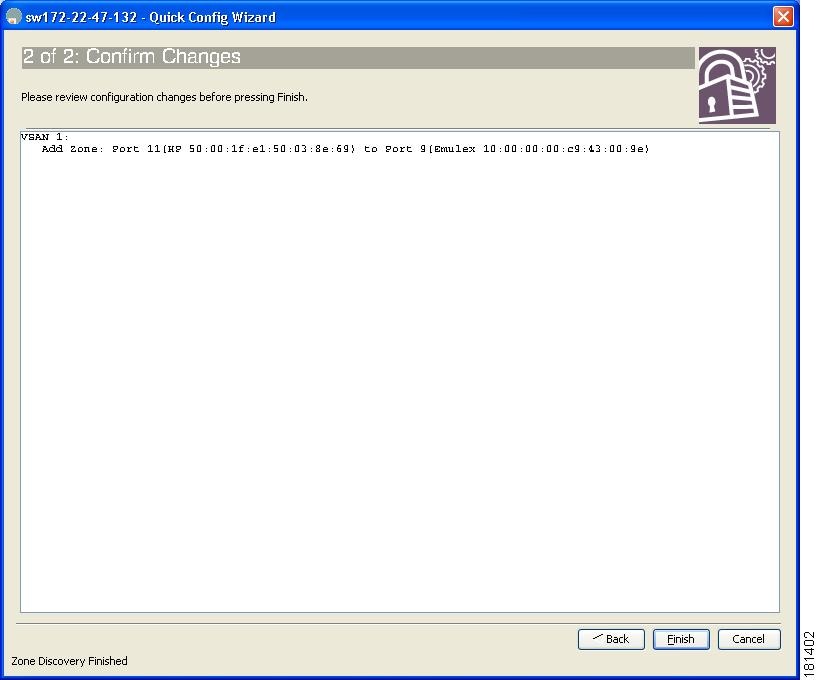
You see a summary of your changes, as shown in Figure 15.Figure 15 Confirm Changes
Step 8
Step 9
Note
Note
10 Create VSANs
To create VSANs, follow these steps:
Step 1
Step 2
Step 3
Figure 16 Device Manager Login
Step 4
Step 5
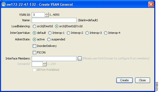
Step 6
Figure 17 VSAN Creation
Step 7
Step 8
Note
This completes the installation of your Cisco MDS 9124 or Cisco MDS 9134 switch. The switch is now ready to use.
11 Need Help?
Obtaining Technical Assistance
Cisco Technical Support provides 24-hour-a-day award-winning technical assistance. The Cisco Technical Support & Documentation website on Cisco.com features extensive online support resources. In addition, if you have a valid Cisco service contract, Cisco Technical Assistance Center (TAC) engineers provide telephone support. If you do not have a valid Cisco service contract, contact your reseller.
Cisco Technical Support & Documentation Website
The Cisco Technical Support & Documentation website provides online documents and tools for troubleshooting and resolving technical issues with Cisco products and technologies. The website is available 24 hours a day at this URL:
http://www.cisco.com/techsupport
Access to all tools on the Cisco Technical Support & Documentation website requires a Cisco.com user ID and password. If you have a valid service contract but do not have a user ID or password, you can register at this URL:
http://tools.cisco.com/RPF/register/register.do