Feedback
Table Of Contents
Fibre Channel Port Logged-In LED
Fibre Channel Port Activity LED
Placing the Switch in Maintenance Mode
Product Overview
This chapter provides an overview of the Cisco MDS 9020 Fabric Switch and its physical features:
Features
The Cisco MDS 9020 Fabric Switch is a 20-port Fibre Channel switch. The switch provides for autonegotiation which allows ports to negotiate for speed at the other end of the link. The Fibre Channel ports autonegotiate at 1 Gbps, 2 Gbps, or 4 Gbps depending on the capabilities of the connected device. Each switch is packaged in a 1 RU enclosure. Management access is provided through 10/100 Ethernet and serial console interfaces.
The Cisco MDS 9020 Fabric Switch provides the following features:
•
20 ports per 1 RU.
•
•
•
•
•
For information about how to configure the Cisco MDS 9020 Fabric Switch, refer to the Cisco MDS 9020 Fabric Switch Configuration Guide and Command Reference.
For information about how to configure the Cisco MDS 9020 Fabric Switch to interoperate with third-party switches, refer to the Cisco MDS 9000 Family Switch-to-Switch Interoperability Configuration Guide.
Power Receptacle
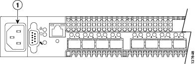
To apply power to the switch, plug the power cord into the switch AC power receptacle, shown in Figure 1-1, and into a 110 or 230 VAC power source.
Figure 1-1 Power Receptacle
Switch LEDs
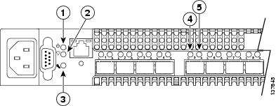
The switch LEDs, show in Figure 1-2, provide information about the switch's operational status. The Switch LEDS include the following:
•
•
Each port has its own Logged-In LED and Activity LED
Figure 1-2 Switch LEDs
Input power LED (Green)
Port Logged-In LED (Green)
Heartbeat LED (Green)
Port Activity LED (Green)
System fault LED (Amber)
Input Power LED
The Input Power LED indicates the voltage status at the switch logic circuitry. During normal operation, this LED is on to indicate that the switch logic circuitry is receiving the proper DC voltages. When the switch is in maintenance mode, this LED is off.
Heartbeat LED
The Heartbeat LED indicates the status of the internal switch processor and the results of the POST. Following a normal power-up, the Heartbeat LED blinks about once per second to indicate that the switch passed the POST and that the internal switch processor is running. In maintenance mode, the Heartbeat LED is on continuously. See the "Power-On Self Test Diagnostics" section for more information about Heartbeat LED blink patterns.
System Fault LED
The System Fault LED turns on to indicate that a fault exists in the switch firmware or hardware. Fault conditions include POST errors and over temperature conditions. The Heartbeat LED shows a blink pattern for POST errors and the over temperature condition. See the "Power-On Self Test Diagnostics" section for more information about Heartbeat LED blink patterns.
Fibre Channel Port Logged-In LED
The Logged-In LED (green) indicates the logged-in or initialization status of the connected devices. After successful completion of the POST, the switch turns off all Logged-In LEDs. Following a successful loop initialization or port login, the switch turns on the corresponding Logged-In LED. This shows that the port is properly connected and able to communicate with its attached devices. The Logged-In LED remains on as long as the port is initialized or logged in. If the port connection is broken or an error occurs that disables the port, the Logged-In LED will flash. See the "Logged-In LED Indications" section for more information about the Logged-In LED.
Fibre Channel Port Activity LED
The Activity LED indicates that data is passing through the port. Each frame that the port transmits or receives causes this LED to turn on for 50 milliseconds. This makes it possible to observe the transmission of a single frame.
Maintenance Button
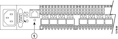
The Maintenance button, shown in Figure 1-3, is a dual-function momentary switch on the front panel. Its purpose is to reset the switch or to place the switch in maintenance mode. Maintenance mode sets the IP address to 10.0.0.1 and provides access to the switch for maintenance purposes. See the "Recovering a Switch Using Maintenance Mode" section for more information about using maintenance mode.
Figure 1-3 Maintenance Button
Resetting a Switch
To reset the switch, use a pointed tool to momentarily press and release (less than 2 seconds) the Maintenance button. The switch will respond as follows:
1.
2.
3.
Placing the Switch in Maintenance Mode
To place the switch in maintenance mode, follow these steps:
Step 1
Step 2
•
•
Step 3
The Heartbeat LED is on continuously while the switch is in maintenance mode. To exit maintenance mode and return to normal operation, momentarily press and release the Maintenance button to reset the switch.
Fibre Channel Ports
The Cisco MDS 9020 Fabric Switch has 20 Fibre Channel ports numbered 1-20. Each of the Fibre Channel ports is served by an SFP optical transceiver and is capable of 1.0625 Gbps, 2.125 Gbps, or 4.250 Gbps speeds. The switch supports the following port operational modes:
•
•
•
•
•
See the Cisco MDS 9020 Fabric Switch Configuration Guide and Command Reference.
Supported SFP Transceivers
Fibre Channel SFP transceivers, in either short wavelength (SWL) or long wavelength (LWL), are available from Cisco and are supported on the Cisco MDS 9020 Fabric Switch. SFP transceivers are field-replaceable. You can use any combination of SFP transceivers that are supported by the switch. The only restrictions are that SWL transceivers must be paired with SWL transceivers, and LWL transceivers with LWL transceivers, and the cable must not exceed the stipulated cable length for reliable communications.
Cisco's Fibre Channel SFP transceivers have LC connectors and comply with 1 Gbps, 2 Gbps, and 4 Gbps Fibre Channel standards as defined in FC-PI 10.0 2.
Transmission ranges for 2 Gbps are as follows:
•
•
•
For transceiver specifications, see "Cable and Port Specifications."
See the Release Notes for Cisco MDS 9020 Fabric Switch for FabricWare Release 2.1(2) for the list of specific supported SFP transceivers. For more information about a specific Cisco SFP transceiver, see the "Cisco Fibre Channel SFP Transceiver Specifications" section. SFP transceivers can be ordered separately or with the Cisco MDS 9020 Fabric Switch.
Ethernet Port
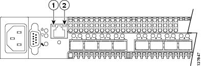
The Ethernet port is an RJ-45 connector that provides a connection to a management workstation through a 10/100 Base-T Ethernet cable. The Ethernet port has two LEDs as shown in Figure 1-4: the Link Status LED (green) and the Activity LED (green). The Link Status LED is on continuously when an Ethernet connection has been established. The Activity LED turns on when data is being transmitted or received over the Ethernet connection.
Figure 1-4 Ethernet Port LEDs
Console Port
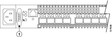
The switch is equipped with an RS-232 serial console port for maintenance purposes as shown in Figure 1-5. You can manage the switch through the console port using the command-line interface. Use a null-modem DB9 cable for the console port connection. See "Connecting the Console Port" section for information about connecting console port to a workstation.
Figure 1-5 Console Port