Feedback Feedback
|
Table Of Contents
Before Configuring SN 5420 Storage Router Software
SN 5420 Storage Router Overview
SCSI Routing Configuration Basics
Storage Router Cluster Overview
Before Configuring SN 5420 Storage Router Software
The Cisco SN 5420 Storage Router installation and configuration tasks consist of the following:
•
Install the SN 5420 Storage Router according to the Cisco SN 5420 Storage Router Hardware Installation Guide.
•
•
This chapter is the starting point for SN 5420 Storage Router software configuration. It provides some very basic, abbreviated information as background to help you understand the storage router features and the software configuration process. It contains the following topics:
•
•
•
SN 5420 Storage Router Overview
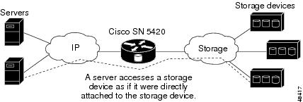
The SN 5420 Storage Router provides servers with IP access to storage through SCSI routing using iSCSI protocol. The iSCSI protocol is a protocol for encapsulating SCSI requests and responses over IP. With SCSI routing, servers use an IP network to access storage as if the servers were directly attached to the storage devices. (See Figure 1-1.)
Figure 1-1 SN 5420 Storage Router Overview
Note
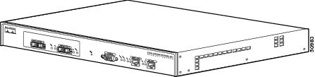
The SN 5420 Storage Router is a 1U rack-mountable chassis (Figure 1-1) consisting of the following main hardware components:
•
•
•
•
•
Figure 1-2 Cisco SN 5420 Chassis
The SN 5420 software provides SCSI routing between servers and the storage devices. The software includes a command line interface (CLI) and web-based GUI for SN 5420 operation, configuration and administration, maintenance, and support tasks.
Each server that requires IP access to storage via the SN 5420 Storage Router needs to have the Cisco Storage Networking iSCSI driver installed. Using the iSCSI protocol, the iSCSI driver allows a server to transport SCSI requests and responses over an IP network. From the perspective of a server operating system, the iSCSI driver appears to be a SCSI or Fibre Channel driver for a peripheral channel in the server.
Figure 1-3 shows a sample storage router network. Servers with iSCSI drivers access the storage routers through an IP network connected to the Gigabit Ethernet interface of each storage router. The storage routers access storage devices through a storage network connected to the Fibre Channel interface of each storage router. A management station manages the storage routers through an IP network connected to the management interface of each storage router. For high availability operation, the storage routers communicate with each other over two networks: the HA network connected to the HA interface of each storage router, and the management network connected to the management interface of each storage router.
Figure 1-3 Sample Storage Router Configuration for SCSI Routing
SCSI Routing Overview
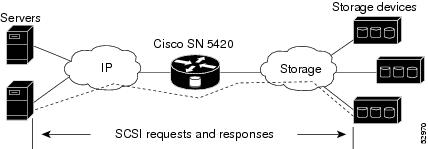
SCSI routing is the routing of SCSI requests and responses between servers in an IP network and storage devices in a storage network. (See Figure 1-4.)
Figure 1-4 SCSI Routing Overview
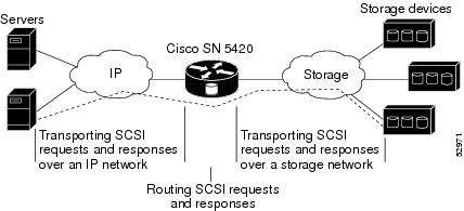
SCSI routing consists of three main actions (Figure 1-5):
•
•
•
Figure 1-5 SCSI Routing Actions
SCSI routing occurs in the SN 5420 Storage Router through the mapping of physical storage devices to iSCSI targets. An iSCSI target (also called logical target) is an arbitrary name for a group of physical storage devices. You can map an iSCSI target to multiple physical devices. An iSCSI target always contains at least one Logical Unit Number (LUN). Each LUN on an iSCSI target is mapped to a single LUN on a physical storage target.
You can choose either of two types of storage mapping: target-and-LUN mapping or target-only mapping. Target-and-LUN mapping maps an iSCSI target and LUN combination to a physical storage target and LUN combination. Target-only mapping maps an iSCSI target to a physical storage target and its LUNs.
With target-and-LUN mapping, an iSCSI target name and iSCSI LUN number are specified and mapped to the physical storage address of one LUN; either a Loop ID + LUN combination, a WWPN + LUN combination, or a WWNN. If the LUN is available, it is made available as an iSCSI LUN and numbered with the iSCSI LUN number specified. For example, if an iSCSI target and iSCSI LUN specified as Database, LUN 9 were mapped to the physical storage address, Loop ID 070, LUN 12, then LUN 12 would be available as one iSCSI LUN. An iSCSI driver would see the iSCSI target named Database, with one iSCSI LUN identified as LUN 9. The iSCSI LUN would appear as one storage device to a server. (See Table 1-1.)
With target-only mapping, an iSCSI target name is specified and mapped to the physical storage address of a storage controller only; either a Loop ID or WWPN. Any LUNs that are available in the storage controller are made available as iSCSI LUNs and are numbered the same as the LUNs in the storage controller. For example, if an iSCSI target specified as Webserver2000 were mapped to the physical storage address Loop ID 050, and LUNs 1 through 3 were available in that controller, those LUNs would become available as three iSCSI LUNs. An iSCSI driver would see the iSCSI target named Webserver2000 as a controller with three iSCSI LUNs identified as LUN 1, LUN 2, and LUN 3. Each iSCSI LUN would appear as a separate storage device to a server. (See Table 1-2.)
Access for SCSI routing is controlled in the servers and a storage router. In a server, the IP address of each storage router with which the server is to transport SCSI requests and responses is configured in the iSCSI driver. In a storage router, an access list identifies which servers can access storage devices attached to it.
Once the access is configured in the servers and a storage router, and once the storage mapping is configured in a storage router, the storage router routes SCSI requests and responses between servers and the mapped storage devices.
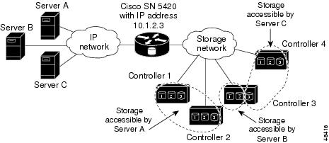
Figure 1-6 represents the concept of storage mapping and access control. In the figure, the SN 5420 Storage Router provides three servers with IP access to disk drives across four disk controllers. The driver in each server is configured to access the storage router IP address 10.1.2.3. An access list in the storage router specifies that servers A, B, and C are allowed to access the mapped storage devices. From the perspective of a server, each disk drive mapped to it appears as a locally attached disk drive. Table 1-3 shows the correlation between an access list, the SN 5420 IP address, and the storage device mapping.
Note
Figure 1-6 Storage Mapping and Access Control Concept
SCSI Routing Configuration Basics
When configuring the storage router for SCSI routing, you will specify the following parameters:
•
•
•
•
•
•
Storage Router Cluster Overview
You can configure Cisco SN 5420 Storage Routers in a cluster to allow the storage routers to back each other up in case of failure. A storage router cluster consists of two configured storage routers connected as follows:
•
•
•
In a cluster, storage routers continually exchange HA information to propagate configuration data to each other and to detect failures in the cluster. The storage routers exchange HA information through two separate networks: one connected to the management interface of each storage router and one connected to the high availability interface of each storage router. To make sure that HA information is exchanged reliably between storage routers, the storage routers balance the transmission of HA information between the management and the high availability interfaces.
A cluster supports up to four active SCSI routing service instances. At any given time, a SCSI routing service instance can run on only one storage router in a cluster. The SCSI routing service instance continues running on the storage router where it was started until it is explicitly stopped or failed over to another storage router in the cluster, or automatically fails over to another storage router because an interface is unavailable or another software or hardware problem occurs.
Each storage router in a cluster can run up to four SCSI routing service instances. For example, if one storage router is already running two SCSI routing service instances, it is eligible to run up to two additional SCSI routing service instances.
Cluster Configuration Basics
When configuring the SN 5420 Storage Router for participation in a cluster, you will specify the following information:
•
•
•
Note
Interface Naming
Configuring the SN 5420 software requires that you understand hardware interface naming. This section describes the interface naming system used with the SN 5420 hardware.
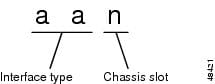
Each SN 5420 interface is assigned a three-character name consisting of two lower-case letters followed by a number. The letters designate the interface type; the number designates the chassis slot occupied by the interface (Figure 1-7).
Figure 1-7 SN 5420 Interface Naming System
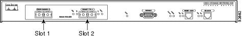
Table 1-4 shows valid interface type designators for the SN 5420; Figure 1-8 shows chassis slot locations for the SN 5420. For example, a Fibre Channel interface in chassis slot 1 would have the name fc1.
Table 1-4 Interface Type Designators
fc
Fibre Channel
ge
Gigabit Ethernet
Figure 1-8 SN 5420 Chassis-Slot Numbering
Where to Go Next
When you are ready to configure the SN 5420 software, proceed to one of the following chapters in this configuration guide according to your needs:
•
•
•
•
•
•
Note