Table Of Contents
Cisco Unified Wireless and Mobile IP
Requirements for a Mobility Solution
Move Discovery, Location Discovery, and Update Signaling
Roaming on a Cisco Unified Wireless Network
Roaming on a Mobile IP-enabled Network
Sample Mobile IP Client Interface and Host Table Manipulation
Cisco Mobile IP Client Characteristics When Roaming on a Cisco Unified Wireless Network
Cisco Unified Wireless and Mobile IP
Introduction
This chapter describes the inter-workings of the Cisco Mobile Client (CMC) over a Cisco Unified Wireless Network (WiSM). This chapter covers the following topics:
•
Different levels of mobility
•
•
•
•
Different Levels of Mobility
There are three different levels of mobility:
•
–
•
–
•
–
One example of Layer 2 roaming across a single Layer 2 network is a wireless network where all the APs have to be on the same subnet and the clients roam between them. This type of deployment allows the clients to roam from one AP to a new AP without requiring a new IP address or the network being mobility-aware.
Layer 3 roaming across a single Layer 2 network follows the previous AP example, but allows the APs to be on different subnets while also allowing the clients to remain in the same subnet as they roam from AP to AP. Layer 3 roaming across any Layer 2 network is a generalized version of this concept to allow roaming across completely different Layer 2 networks (cellular, wired, and 802.11 wireless).
Roaming in networks can be seamless roaming or seamless mobility. Seamless mobility is where both the mobile client applications and the remote applications do not notice any change in end-to-end IP addressing; end applications can use or embed these IP addresses into their data packets without concern that they will be undeliverable. This emulates the case where two clients are on a wired network and not mobile. The Cisco Unified Wireless Network and Mobile IP both provide seamless mobility.
The Cisco Unified Wireless Network is an example of seamless Layer 3 roaming across a single Layer 2 network, while the CMC using Mobile IP (RFC 3344) is an example of seamless Layer 3 roaming across any Layer 2 network. That is, in the Cisco Wireless Unified Network, Layer 3 roaming is restricted to roaming across APs in the mobility group. With Mobile IP, any Layer 2 network (wired, 802.11 wireless, or cellular) can be used for roaming.
These two different solutions perform the same functionality, so they require the same components.
Requirements for a Mobility Solution
There are the following five requirements for every mobility solution:
•
•
•
•
•
These requirements are covered in the following sections.
Location Database
A location database keeps track of the roaming client. This is very important because the location database is actually forwarding all packets destined for the client to the current location of the roaming client. That is, the location database receives packets destined for the client and forwards the packets on to the client.
In the Cisco Unified Wireless Network, the first hop router attracts packets for the wireless clients through the routing protocol running on that network, and forwards them via a trunk to the controller. Each controller keeps a location database of wireless clients as they roam from one AP to another AP associated to the controller. If the wireless client then roams to an AP on another controller (a foreign controller), that controller can query other controllers in the mobility group to see if this is a new client or a roaming client. If it is a roaming client, the first hop router near the home controller still attracts packets destined to the wireless client, but instead of the controller forwarding them on to one of its associated APs, it forwards the packets to the foreign controller, which then forwards them on to the client.
In Mobile IP, the Home Agent (HA) is the location database. Because it runs the network routing protocol, it attracts packets for the Mobile IP Client and forwards them to the current location of the client. Unlike the Cisco Unified Wireless Network, the HA is not a distributed database between WLCs. It does not query other HAs. As far as it is concerned, there is only one location database: itself. This is where the location database mechanisms for the two solutions differ.
Move Discovery, Location Discovery, and Update Signaling
The discovery, location discovery, and update signaling requirements are grouped in this section because in the Cisco Unified Wireless Network, they are performed at the same time. When the wireless client roams to a new AP, it needs to associate to the wireless network. During the association process, packets are sent to the controller to identify the wireless client and the location (AP) from where the wireless client is trying to associate. This information is used by the controller to update its mobility database. If the client has roamed to another controller, the original controller for the wireless client forwards packets destined to the wireless client to the remote controller.
Move discovery is done in the Cisco Unified Wireless Network by the network that knows to which AP the wireless client is associated. Update signaling is done by the first packets sent to the controller from the wireless client. These packets can be authentication packets.
In Mobile IP, the Mobile IP Client authenticating to the wireless network does not provide the HA with any information. Additionally, the client is responsible for recognizing when it has moved. The client typically detects movement in two ways. One way is through the Windows operating system's Layer 2 notification feature called Media Sense. This feature detects the disconnect and reconnect of different Layer 2 media when roaming between APs and sends the Windows operating system a signal when it occurs. This allows the interface to try and renegotiate its DHCP address with the DHCP server.
The second method for detecting movement is through FA advertisements. These advertisements tell the Mobile IP Client which subnet it is on. If the Mobile IP Client receives one of these periodic messages, it can tell it has moved to a new subnet. These move discovery methods are typically used for Mobile IP. There are other methods specified in RFC 3344, but generally these are not used in working clients. The next section explains location discovery for Mobile IP.
Location discovery is typically done in one of two ways in Mobile IP. In the first method, it receives an FA advertisement telling it what the IP address is for the FA. The Mobile IP Client can check this address against the address it already has from the FA and tell if the FA has changed locations. The Mobile IP Client can then forward this IP address to its HA so that the HA can forward packets to the Mobile IP Client. In the second method, the client is acting as its own FA, it receives a new DHCP IP address, and informs the HA it has a new address for forwarding packets.
Finally, update signaling in Mobile IP is done via the registration request (RRQ) and registration reply (RRP) between the Mobile IP Client and the HA. These packets have a cryptographic signature (via shared keys) to ensure that they are not changed in transit.
For more information, see the following URL: http://www.cisco.com/en/US/products/ps6590/products_ios_protocol_group_home.html.
Path Re-establishment
Path re-establishment is the mechanism used to allow the client to receive packets that are destined for it from the location database. This is typically some type of tunneling where the original packet is encapsulated into another packet.
In the Cisco Unified Wireless Network, packets are forwarded to wireless clients on associated APs through the "always up" LWAPP tunnel. For wireless clients that have roamed to another controller, the controllers use a dynamic Ethernet over IP tunnel for all packets forwarded to other controllers in the mobility group.
In Mobile IP, there are several types of tunnels available (GRE, UDP, and IP in IP) and the type of tunnel used depends on the equipment between the Mobile IP Client and HA, and whether the HA supports that type of encapsulation. For example, if the HA detects that the client is behind a NAT gateway, it uses UDP tunneling. If the Mobile IP Client requests GRE tunneling and the HA can support the tunneling, it uses GRE. Typically, the Mobile IP Client requests IP in IP tunneling, and all RFC-compliant HAs can support this type of tunneling.
Roaming on a Cisco Unified Wireless Network
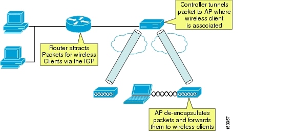
A Cisco Unified Wireless Network acts as a mobility proxy for the wireless client. This allows the network to provide seamless mobility to the wireless client without any extra software or required information on the wireless client (see Figure 14-1).
When a wireless client associates to an AP, the AP forwards the client packets to the controller via the LWAPP tunnel set up between the controller and AP (the LWAPP tunnel is set up between the AP and controller at AP boot time). For the controller, the LWAPP tunnel allows it to do the following:
•
•
•
•
For the client, the LWAPP tunnel allows the client to see its default gateway as being one hop away, even though it might physically be several hops away.
Figure 14-1 Roaming on a Cisco Unified Wireless Network
If the client requests a DHCP address, the controller either gives the client an address from its local DHCP pool (if defined) or fills in the gateway address in the DHCP request for an external DHCP server. In either case, the controller modifies any returning offers so that the DHCP server's address is set to the address on its virtual interface. Even though the virtual IP address is not in any routing table (typically 1.1.1.1), it still allows the controller to intercept any DHCP renewals on wireless clients that occur with the Microsoft Windows operating system (using Microsoft Media Sense) when it roams between APs. In addition, if the same address is on all controllers' virtual addresses, it allows other controllers to intercept the DHCP renewal from the client when it roams to a new AP associated to a different controller.
The wireless client can easily roam between any APs associated to the controller because the controller simply keeps track of the wireless client's current location and forwards the packets destined to that client into the correct LWAPP tunnel and on to the associated AP. When the client roams to an AP associated to a different controller, the remote controller queries other controllers in the mobility group to see if the client has roamed from another controller, and the controllers dynamically set up an Ethernet over IP tunnel for forwarding client traffic from the original controller.
Traffic originating from the wireless client that has roamed to an AP associated to another controller can be handled in two ways. Typically, the foreign controller modifies the destination MAC address of any packet from the wireless client to its gateway MAC address before forwarding it on to the controller gateway. The second method occurs if mobility anchoring is enabled on the original controller; the traffic is forwarded back to the original controller. This allows traffic to be sent to the correct gateway in case RPF checks are enabled.
Roaming on a Mobile IP-enabled Network
A Mobile IP-enabled network has three components:
•
•
•
Only two of the three components are actually required for a mobility solution: the MN and HA. The third component, the FA, is optional because the MN can act as its own FA by using DHCP for a local IP address. In this case, the tunnel ends at the MN.
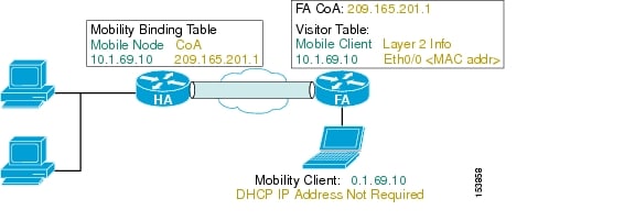
In Figure 14-2, the MN is given an IP address (10.1.69.10) local to the HA. To the rest of the network, the MN looks like it is directly attached to the HA. The HA then uses its mobility binding table to forward packets to wherever the MN is currently located. It is the responsibility of the MN to update its location with the HA. The FA de-encapsulates the packets destined for the MN and forwards them out its interface. It gleans the information it needs by being an active party in the registration process with the HA. The MN actually sends its packets to the FA, and the FA checks the packets and generates new IP headers to forward the information onward to the HA. The FA can also provide reverse tunneling for the MN originated packets back to the HA, instead of simply forwarding through the normal switching process. Reverse tunneling allows packets from the MN to always exit the HA and pass any reverse path forwarding (RPF) checks.
Figure 14-2 HA and FA Tunneling
Unlike the Cisco Unified Wireless Network where the network proxies or provides the wireless client with seamless mobility and no information is stored on the client, the Mobile IP Client, or MN needs to know three pieces of information to function:
•
•
•
These three pieces of information can be dynamically discovered or generated but are typically manually configured on the MN. DHCP can be used to convey the HA address to the MN via option 68. The HA can dynamic assign an IP address to the MN to be used as its home address when it registers for the first time. By using the Cisco Zero Configuration Client (ZECC) feature, the MN and HA can automatically generate a shared secret key from the windows login credentials.
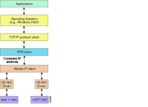
When the Cisco Mobile IP Client is loaded on a Windows host, the Mobile IP Client function rests between the physical interfaces and the VPN client and TCP/IP stack (see Figure 14-3). The Mobile IP Client function sends its home address up the TCP/IP stack so that the host applications, including the VPN client, see a constant IP address as the MN roams across the different network locations or different networks. The physical interfaces might or might not have IP addresses during roaming depending on whether an FA is present on the subnet.
Figure 14-3 Mobile IP Function Position in the Microsoft Operating System
The CMC controls that interface with host-originated packets are transmitted by:
•
•
This virtual adapter looks like any physical adapter to the host (see the example in Sample Mobile IP Client Interface and Host Table Manipulation). When the adapter is enabled, the Mobile IP Client modifies the forwarding table to give the CMIPDRV adapter the best metric, and the Windows operating system forwards host originated packets to the CMIPDRV adapter. This allows the Mobile IP Client to hide the true interface used to transmit the packet and to modify the host's forwarding behavior.
In the example, there are three interfaces:
•
•
•
Not e that the Mobile IP Client has manipulated the host's forwarding table so that the lower metric interface is the Mobile IP Client's interface. The higher metric routes can be safely ignored when looking at the table. The real DHCP IP address on the wireless interface is 10.20.41.12. Any route with a destination address to this gateway has had its metric raised and the default gateway is via the CMIPDRV interface.
Sample Mobile IP Client Interface and Host Table Manipulation
C:\>ipconfigWindows IP ConfigurationEthernet adapter Local Area Connection:Connection-specific DNS Suffix . :IP Address . . . . . . . . . . . : 10.20.30.249Subnet Mask. . . . . . . . . . . : 255.255.255.0Default Gateway . . . . . . . . :Ethernet adapter CMIPDRV:Connection-specific DNS Suffix . : srnd3.comIP Address . . . . . . . . . . . : 10.20.32.11Subnet Mask. . . . . . . . . . . : 255.255.255.0Default Gateway . . . . . . . . : 10.20.32.1Ethernet adapter Wireless Connection:Connection-specific DNS Suffix . :IP Address . . . . . . . . . . . : 0.0.0.0Subnet Mask. . . . . . . . . . . : 0.0.0.0Default Gateway . . . . . . . . :C:\>route print==========================================================================================Interface List0x1............................MS TCP Loopback interface0x2...00 d0 b7 a6 b8 47........Intel (R) 82559 Fast Ethernet LAN on Motherboard- Packet Scheduler Miniport0x3...00 4d 69 70 56 61 .......Cisco Systems Mobile Adapter - Packer SchedulerMiniport0x10005...00 12 f0 7c a5 ca......Intel (R) PRO/Wireless 2915ABG Network Connection - Deterministic Network Enhancer Miniport======================================================================================================================================================================================Active Routes:Network Destination Netmask Gateway Interface Metric0.0.0.0 0.0.0.0 10.20.32.1 10.20.32.11 110.20.30.0 255.255.255.0 10.20.30.249 10.20.30.249 110.20.30.0 255.255.255.0 10.20.32.1 10.20.32.11 110.20.30.249 255.255.255.255 127.0.0.1 127.0.0.1 110.20.32.0 255.255.255.0 10.20.32.11 10.20.32.11 2010.20.32.11 255.255.255.255 127.0.0.1 127.0.0.1 2010.20.41.0 255.255.255.0 10.20.41.12 10.20.41.12 2510.20.41.0 255.255.255.0 10.20.32.1 10.20.32.11 110.20.41.12 255.255.255.255 127.0.0.1 127.0.0.1 2510.255.255.255 255.255.255.255 10.20.30.249 10.20.30.249 110.255.255.255 255.255.255.255 10.20.32.11 10.20.32.11 2010.255.255.255 255.255.255.255 10.20.41.12 10.20.41.12 25127.0.0.0 255.0.0.0 127.0.0.1 127.0.0.1 1224.0.0.0 240.0.0.0 10.20.30.249 10.20.30.249 1224.0.0.0 240.0.0.0 10.20.32.11 10.20.32.11 20224.0.0.0 240.0.0.0 10.20.41.12 10.20.41.12 25255.255.255.255 255.255.255.255 10.20.30.249 10.20.30.249 1255.255.255.255 255.255.255.255 10.20.32.11 10.20.32.11 1255.255.255.255 255.255.255.255 10.20.41.12 10.20.41.12 1Default Gateway: 10.20.32.1===========================================================================================Persistent Routes:NoneWhen an MN makes a Layer 2 connection, it starts two different threads. One thread is a DHCP process to obtain a local IP address so that it can use the IP address for a co-located care of address (CCoA) registration to the HA if there is no Foreign Agent (FA) on the subnet; the other thread looks for a FA on the subnet to which it is attached.
If the MN finds an FA on the subnet, it uses the care of address (CoA) advertised by the FA to register (update) with its location database, the HA, and reject any DHCP offers. An FA on the subnet does two things for the Mobile IP Client:
•
•
The FA can forward traffic to the MN because the MN is on a directly attached interface. The FA maintains an entry in a table, called a visitor table, which has the MN home address, and to which interface the MN is currently attached as well as Layer 2 encapsulation information. This way, when the HA tunnels a packet for the MN to the FA, the FA simply de-encapsulates the packet and looks into its visitor table for the interface the MN is on and forwards it directly out the interface. Because of this table, the MN does not need a local IP address on the subnet.
If there is no FA on the subnet, the MN requires a local IP address to which the HA can forward packets. After it receives a DHCP address, the MN registers (updates) the HA and builds a tunnel directly between the MN and the HA. All de-encapsulation of packets is performed by the MN.
If reverse tunneling (where the host packets are tunneled back to the HA) is enabled, the overall solution is analogous to the Cisco Unified Wireless Network. Packets from the client are tunneled and forwarded to a location database and packets destined to the client are received by the location database and tunneled and forwarded to the current location of the client.
Figure 14-2 and Figure 14-3 are similar in functionality except that the HA is a router and can also attract packets for the Mobile IP Client through the use of an IGP and tunnel packets to the MN.
Cisco Mobile IP Client Characteristics When Roaming on a Cisco Unified Wireless Network
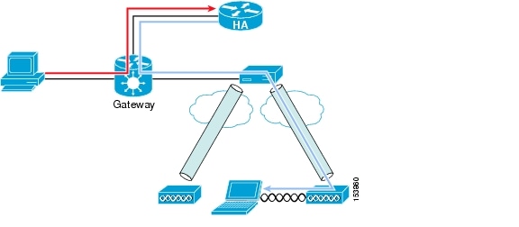
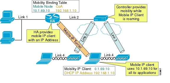
Traffic destined for the MN must pass through the HA and the controller to reach a MN on the wireless network. If reverse tunnel is enabled, the packet must pass back through the HA before being forwarded to any other host. Figure 14-4 shows the traffic patterns from a remote host to the MN. The orange flow line shows that the network believes the MN is attached to the HA. The blue flow line shows the tunneled packet to the MN. If another wireless client sent packets to the MN, that traffic would also have to traverse the HA.
Figure 14-4 Traffic Flow to MN
Because of the routing of traffic to and from the MN from other hosts, the general goal in the placement of the controller and HA is to minimize the summation of all links. In Figure 14-5, link 1 cannot be minimized because the hosts' locations are random. The same goes for link 4 because mobile hosts' locations cannot be fixed. Link 3 cannot be minimized because the RF survey determines AP placement. This leaves the link between the controller and HA, link 2.
Figure 14-5 Mobile IP and Cisco Unified Wireless Network
There are two basic HA placement principles:
•
•
The first principle is simply a way to minimize traffic links from any host in the network to any place in the network. The second principle follows the logic that the only link you can minimize is link 2 between the HA and controller. This means the controller and HA should be co-located whenever possible. The best location is directly off the core in the data center with centralized controllers.
When a Mobile IP Client is roaming on a Cisco Unified Wireless Network, it maintains the same DHCP IP address while roaming, allowing it to maintain the same CCoA address. The Cisco Unified Wireless Network handles the underlying mobility and the Mobile IP Client does not see any changes as it roams from AP to AP. To the Mobile IP Client, it is as if it is roaming on a single large subnet. Accordingly, nothing changes at the Mobile IP Client level until it roams off of the wireless network.
Note
Currently, the CMC does not behave in this manner. When it roams from AP to AP, even though it retains the same DHCP address as it roams, with each roam, it reregisters with the HA, as though it received a new DHCP IP address. Although this is a minor nuisance, it still taxes the resources of the home agent.
Another characteristic of the Mobile IP Client is that it runs in parallel with the Microsoft Windows operating system. When the Mobile IP Client controls the DHCP behavior of the interface instead of the Windows TCP/IP stack, the Windows operating system gives a connectivity warning for the interface indicating that the interface is configured for DHCP but did not receive an IP address. This is normal operation in Mobile IP but the Windows operating system considers it a warning situation. In addition, the Mobile IP Client configures the interface with a 0.0.0.0 IP address. This can be confusing to users troubleshooting the connectivity problem brought up by the Windows operating system.
Another characteristic of the CMC is that it does not yet use the Cisco Zero Configuration Client (ZECC) in version 1.0. For more information on ZECC, see the following URL: http://www.cisco.com/en/US/technologies/tk648/tk369/tk425/technologies_white_paper0900aecd8021a77d.html.
This forces network engineers to configure users in two places:
•
•
Version 1.0 of the CMC requires a RADIUS server for storage of MN keys (keys can also be locally stored on the HA but this does not scale). Cisco recommends Cisco Secure Access Control Server (ACS) 4.0.
One final note: The current version of the roaming server does not have the ability to configure the Cisco HA, and the HA is considered an external HA. This limits the roaming server to a RADIUS database in the CMC architecture. The roaming server is a GUI-based AAA server that can also configure ipUnplugged's HA. Future versions of Roaming server will allow configuration of Cisco HA.